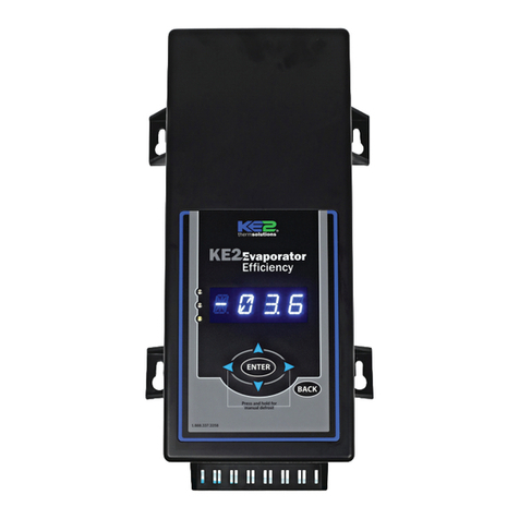
KE2 EvaporatorEfciency
Quick Start Guide
Q.1.3 November 2017
Page 18
Setpoints Menu
Parameter Name Description Range Default Parameter Name
ROOM TEMP Walk-in freezer or cooler room temperature to be maintained -50°F to 90°F -10°F ROOM TEMP
DEFROST TYPE Method of defrost used on the evaporator coil: Electric, Air, Hot Gas with Liquid Line Solenoid/Compressor relay o, Hot Gas with
Liquid Line Solenoid/compressor relay on ELEC, AIR, HOT GAS COMP ON, HOT GAS COMP OFF ELEC DEFROST TYPE
VALVE TYPE Type of valve used on the system: mechanical, pre-congured electric, custom EEV conguration MECHANICAL, KE2 RSV, KE2 HSV, SER/SEI 1 TO 20, SER B TO L, SEI 30, SEI 50, SEH, ETS12 TO 50,
ETS100, ETS250/400, CAREL, CUSTOM; MECHANICAL VALVE TYPE
Custom
EEV only
MOTOR TYPE If VALVE TYPE = CUSTOM: The motor type used in the valve BIPOLAR, UNIPOLAR BIPOLAR MOTOR TYPE
MOTOR STEP RATE If VALVE TYPE = CUSTOM: The motor speed setting in number of steps per second 30 to 400 steps/second 200 steps MOTOR STEP RATE
MAX VALVE STEPS If VALVE TYPE = CUSTOM: The total number of steps required to move the valve from closed to fully open 200 to 6400 steps 1600 steps MAX VALVE STEPS
SUPERHEAT The superheat value that the controller will maintain, (not applicable if VALVE TYPE = MECHANICAL) 5°F to 30°F 8°F SUPERHEAT
MAX OPERATING PRES The maximum allowable suction pressure, (not applicable if VALVE TYPE = MECHANICAL) 10-500 psig if R-744 selected, 10-300psig if R-410A selected, 10-150 psig all other refrigerants 150 psig MAX OPERATING PRES
REFRIGERANT The type of refrigerant used in the refrigeration system 404A, R507, 407A, 407C, 422A, 422D, 134A, R22, R717, 438A, 408A, 409A, 407F, 410A, 448A,
449A, 450A, 513A, R744 404A REFRIGERANT
AUX TEMP 4 MODE Conguration mode of the auxiliary temperature sensor DISABLED, MONITOR, T4 ROOM TEMP, T4 COIL TEMP T4 COIL TEMP AUX TEMP 4 MODE
AUX TEMP 1 MODE Conguration mode of the auxiliary temperature sensor (Not available if EEV is selected) T1 SUCTION TEMP, MONITOR, T1 ROOM TEMP, 2ND COIL TEMP T1 SUCTION AUX TEMP 1 MODE
AUX RELAY MODE Conguration mode of the auxiliary relay. ALARM RELAY, 2ND COMP RELAY, 2ND FAN RELAY, 2ND DEFR RELAY, 2 SPEED FAN CTL, LIGHT
RELAY, PERM DEFROST RELAY ALARM RELAY AUX RELAY MODE
FAN SPEED Provides 0-10V DC signal to control variable speed -100% to 100% 0.000 (O) FAN SPEED
MIN COMP RUN TIME Minimum amount of time the liquid line solenoid/compressor relay must remain on after it is energized 0 to 15 minutes 2 minutes MIN COMP RUN TIME
MIN COMP OFF TIME Minimum amount of time the liquid line solenoid/compressor relay must remain o before it can be energized again. 0 to 15 minutes 5 minutes MIN COMP OFF TIME
REFRIG FAN MODE Fan operation while in refrigeration mode ON WITH COMPRESSOR, PERMANENT, MANAGED, CONTROL FOR TITLE 24 ON WITH COMPRESSOR REFRIG FAN MODE
DEFROST MODE The method the controller uses to determine when to initiate a defrost. DEMAND, SCHEDULED, RUN TIME DEMAND DEFROST MODE
DEFROSTS / DAY If DEFROST MODE = SCHEDULED: The number of evenly spaced defrosts per day the controller will initiate. 0 to 8 5 DEFROSTS / DAY
1ST DEFROST DELAY If DEFROST MODE = SCHEDULED: The amount of time from controller power up until the rst defrost is initiated. 0 to 240 minutes 120 minutes 1ST DEFROST DELAY
DEFROST FAN STATE Whether or not to run the evaporator fans during defrost ON/OFF OFF if DEFROST TYPE = ELEC, HOT GAS COMP ON, HOT GAS
COMP OFF
ON if DEFROST TYPE = AIR DEFROST FAN STATE
DEFROST TERM TEMP The temperature the coil sensor(s) must exceed in order to terminate defrost. The controller’s defrost mode is complete at this point. 35°F to 90°F 50°F if DEFROST TYPE = ELEC, HOT GAS COMP ON, HOT GAS
COMP OFF
40°F if DEFROST TYPE = AIR DEFROST TERM TEMP
DEFROST PARAMETER if DEFROST MODE = DEMAND: Coecient to KE2 Defrost algorithm 0 to 90 30 if DEFROST TYPE = ELEC
10 if DEFROST TYPE = HOT GAS COMP ON, HOT GAS COMP OFF
40 if DEFROST TYPE = AIR DEFROST PARAMETER
MAX DEFROST TIME If DEFROST MODE = SCHEDULE or RUNTIME: The maximum amount of time the defrost relay will be energized. (Not available if DEFROST MODE = DEMAND) 0 to 90 minutes
45 minutes if DEFROST TYPE = ELEC
10 minutes if DEFROST TYPE = HOT GAS COMP ON, HOT GAS
COMP OFF
40 minutes if DEFROST TYPE = AIR
MAX DEFROST TIME
DRAIN TIME Time to be in drain mode (drip time) 0 to 15 minutes 2 minutes DRAIN TIME
COMP RUN TIME If DEFROST MODE = RUN TIME: The amount of time liquid line solenoid/compressor relay is energized before the next defrost is initiated. 0 to 24 hours 6 hours COMP RUN TIME
ELEC DEFROST MODE If DEFROST TYPE = ELEC: Whether to leave the defrost relay energized during the defrost cycle or to utilize advanced defrost algorithm. PULSE, PERMANENT PULSE ELEC DEFROST MODE
FAN DELAY TEMP After defrost, the coil sensor reading must fall below this temperature set point in order for the controller to resume normal fan operation. -40°F to 35°F 20°F FAN DELAY TEMP
MAX FAN DELAY TIME Maximum amount of time after defrost to resume normal fan operation. 0 to 20 minutes 2 minutes MAX FAN DELAY TIME
PUMP DOWN TIME Minimum amount of time between de-energizing the liquid line solenoid/compressor relay and energizing the defrost relay. 0 to 90 minutes 0 minutes if DEFROST TYPE = ELEC or AIR,
2 minutes if DEFROST TYPE = HOT GAS ON/OFF PUMP DOWN TIME
MULTI AIR TEMP CTRL Select control method to use with multiple room temperature sensors AVERAGE, WARMEST WARMEST MULTI AIR TEMP CTRL
Bonded
Control-
lers Only
MULTI EVAP COOL Select type of multi evaporator control - options are synchronous or independent SYNC, INDEPENDENT SYNC MULTI EVAP COOL
MULTI EVAP DEFROST Select whether to have all bonded controllers initiate defrost mode at the same time or independently. SYNC, INDEPENDENT SYNC MULTI EVAP DEFROST
MULTI EVAP SENSOR Select whether or not to share room temperature, coil temperature and suction pressure sensor data with bonded controllers. SHARED, NOT SHARED SHARED MULTI EVAP SENSOR
HIGH TEMP ALARM OFFSET The number of degrees above ROOM TEMP for a HIGH TEMP ALARM condition. 0°F to 99.9°F 10°F HIGH TEMP ALARM OFFSET
HIGH TEMP ALARM DELAY Minutes the room temperature must remain above ROOM TEMP + HIGH TEMP ALARM OFFSET before issuing a HIGH TEMP ALARM 0 to 120 minutes 60 minutes HIGH TEMP ALARM DELAY
LOW TEMP ALARM OFFSET The number of degrees below ROOM TEMP for a LOW TEMP ALARM condition. 0°F to 20°F 4°F LOW TEMP ALARM OFFSET
LOW TEMP ALARM DELAY Minutes the room temperature must remain below ROOM TEMP - LOW TEMP ALARM OFFSET before issuing a LOW TEMP ALARM 0 to 30 minutes 10 minutes LOW TEMP ALARM DELAY
DOOR ALARM DELAY If DIG IN (1, 2 and/or 3) MODE = DOOR SWITCH: The amount of time, in minutes, before an alarm condition is initiated if door is open and room
temperature is 5 degrees above ROOM TEMP + AIR TEMP DIFF 0 to 180 minutes 30 minutes DOOR ALARM DELAY
DIG IN 1 MODE Sets the function of the digital input DISABLED, 2ND ROOM TEMP, DOOR SWITCH, EXT ALARM, SYSTEM OFF DOOR SWITCH DIG IN 1 MODE
DIG IN 1 STATE Sets whether the switch activates when opened or closed OPEN, CLOSED CLOSED DIG IN 1 STATE
DIG IN 2 MODE Sets the function of the digital input DISABLED, 2ND ROOM TEMP, DOOR SWITCH, EXT ALARM, SYSTEM OFF, DEFR INTERLOCK,
DEFR LOCKOUT DISABLED DIG IN 2 MODE
DIG IN 2 STATE Sets whether the switch activates when opened or closed OPEN, CLOSED CLOSED DIG IN 2 STATE
DIG IN 3 MODE Sets the function of the digital input DISABLED, 2ND ROOM TEMP, DOOR SWITCH, EXT ALARM, SYSTEM OFF, LIGHT SWITCH SYSTEM OFF DIG IN 3 MODE
DIG IN 3 STATE Sets whether the switch activates when opened or closed OPEN, CLOSED CLOSED DIG IN 3 STATE
2ND ROOM TEMP If DIG IN (1, 2 and/or 3)MODE = 2ND ROOM TEMP: This value becomes the ROOM TEMP setpoint when the digital input is active -50°F to 90°F -50°F 2ND ROOM TEMP
SUCT PRES OFFSET An oset added or subtracted from the suction line pressure transducer reading, if needed -5.0 to 5.0 psig 0.0 psig SUCT PRES OFFSET
SUCT TEMP OFFSET An oset added or subtracted from the suction temperature sensor reading, if needed -5.0°F to 5.0°F 0.0°F SUCT TEMP OFFSET
AIR TEMP OFFSET An oset added or subtracted from the room temperature sensor reading, if needed -5.0°F to 5.0°F 0.0°F AIR TEMP OFFSET
COIL TEMP OFFSET An oset added or subtracted from the coil temperature sensor reading, if needed -5.0°F to 5.0°F 0.0°F COIL TEMP OFFSET
AUX TEMP OFFSET An oset added or subtracted from the auxiliary temperature sensor reading, if needed -5.0°F to 5.0°F 0.0°F AUX TEMP OFFSET
TEMP UNITS Units for temperature’s display in °F or °C FAHRENHEIT/CELSIUS FAHRENHEIT TEMP UNITS
AIR TEMP DIFF The number of degrees above ROOM TEMP before the controller will go into REFRIGERATION mode 0.1°F to 5°F 1°F AIR TEMP DIFF
EXTREME TEMP DIFF ADVANCED TOPIC: Call KE2 Therm for assistance EXTREME TEMP DIFF
PROPORTIONAL A coecient to the valve control algorithm that increases valve responsiveness 0 to 255 3 PROPORTIONAL
INTEGRAL A coecient to the valve control algorithm that increases valve responsiveness 0 to 255 5 INTEGRAL
DERIVATIVE Should not be adjusted unless instructed by KE2 Therm technical support 0 to 255 3 DERIVATIVE
Table 3 - Controller Menus and Menu Parameters
© Copyright 2017 KE2 Therm Solutions, Inc., Washington, Missouri 63090