Instek Digital DVR5000-2U Series User manual

DVR5000-2U Series
Digital Video Recorder QUICK START GUIDE

Quick Start Guide DVR5000-2U Series
WWW.INSTEKDIGITAL.COM | Page 2
THANK YOU FOR PURCHASING A QUALITY
PRODUCT FROM INSTEK DIGITAL.
THIS QUICK START GUIDE WILL PROVIDE INSTRUCTIONS FOR
CONFIGURING THE NVR (SERVER) AND VIEWING VIDEO FROM
THE COMMAND CENTER APPLICATION (CLIENT SOFTWARE).
INSTEK DIGITAL SEPARATES THE CLIENT AND SERVER INTO TWO
DISTINCT ENTITIES. THIS SETUP ALLOWS PLACEMENT OF
THE SERVER IN A SECURE, TAMPER-PROOF LOCATION, FURTHER
ENHANCING YOUR SECURITY PROTOCOLS.
The MatriVideo™ DR5000-2U is a state-of-the art recording system that
provides DVD quality video (CIF~D1) by using the most advanced H.264
compression technology. It is based on the Linux operating system which is
considered to be the most stable and secure operating system in the world.

Quick Start Guide DVR5000-2U Series
WWW.INSTEKDIGITAL.COM | Page 3
BOX CONTENTS
MatriVideo DVR x 1
•
HDD Tray x 8
•
Document CD x1
•
Software CD (CCOne) x 1
•
Quick Start Guide x 1
•
Screws (Set) x 1
•
Power Cable
•
Warranty Card x1

Quick Start Guide DVR5000-2U Series
WWW.INSTEKDIGITAL.COM | Page 4
Front Panel
USB ports
Reset button
Power LED
Power button
Rear Panel (5316-5416)
PS/2 Keyboard Connector
COM Port
VGA Port
USB Ports
Ethernet Connector
Speaker out /
audio line in
BNC Ports for Analog Video Input
RCA Ports for Analog Audio Input
LCD display
Power Socket
Rear Panel (5408)
Power Socket
PS/2 Keyboard Connector
COM Port
USB Ports
VGA Port
Ethernet Connector
Speaker out /
audio line in
RCA Ports for Analog Audio Input
BNC Ports for Analog Video Input

Quick Start Guide DVR5000-2U Series
WWW.INSTEKDIGITAL.COM | Page 5
STEP 1: INSTALL HARD DRIVES
a. Insert HDD into tray and use four screws to secure it in place.their slots.
b. Use your thumb to press the key hole of the HDD tray and push it up to unlock the
HDD tray. Insert the HDDs (with the trays) into their slots.
c. Connect one end of the BNC cable to the camera and the other to the video and audio-
in ports. (Red on the AV line indicates video, white indicates audio.)
d. To connect a PTZ camera connect an RS-232 cable between the convertor and the DVR
COM1 port
e. Connect the PTZ camera and the RS-232 RS-485 convertor by using the control cable.
f. To connect the DVR to the network, connect one end of the RJ45 to the switch and the
other end to the RJ45 port on the DVR.
RCA Ports for Analog Audio Input
BNC Ports for Analog Video Input

Quick Start Guide DVR5000-2U Series
WWW.INSTEKDIGITAL.COM | Page 6
g. For extra COM port or RS485 direct connection, please contact Instek for the optional
USB to RS232/485 converte
STEP 2: POWER ON THE NVR
a. Connect the power cord.
b. Power on the NVR. The booting process will take a few minutes to complete. When
the process is complete the following information will display on the LCD screen:
STEP 3: INSTALL COMMAND CENTER SOFTWARE
a. Insert the Command Center Series CD into the CD-ROM drive of your personal laptop
or desktop computer and run the Command Center Setup application setup.
STEP 4: CONFIGURE THE NVR
a. Configure NVR either via Putty (see step 2) or connect a keyboard and a monitor
directly to NVR (jump to step 3).
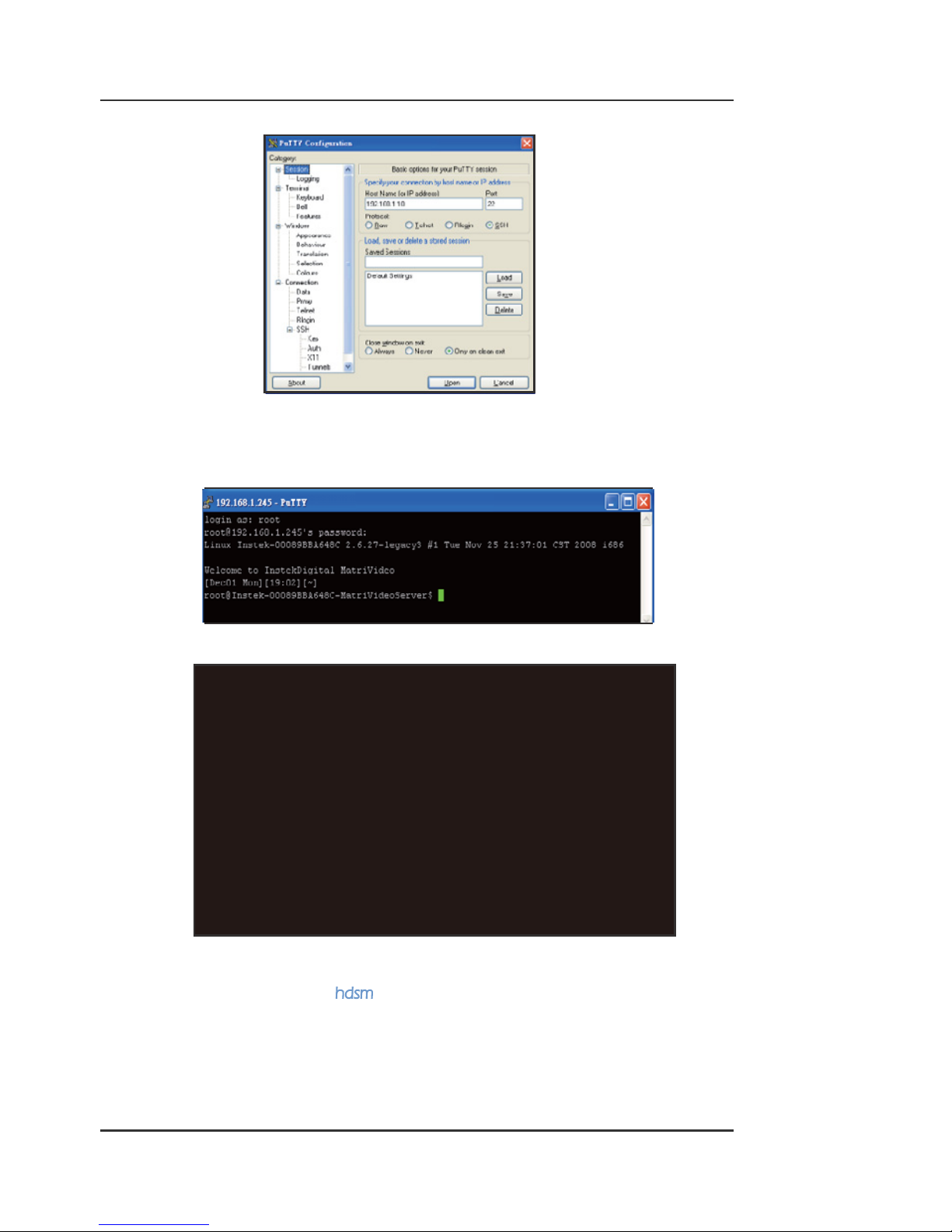
b. Putty is an SSH program used to connect to the NVR remotely. On your laptop or
desktop, navigate to: > > > .
A telnet window will open. Enter the IP address of the NVR in the box labeled
Click to start a remote connection (telnet session) with the
NVR.
Note: Command Center series software comes in four varieties: Command Center,
Command Center Dual, Command Center Lite, and Command Center One.
Warning: After making changes to the hDVR system configuration, run the
command saveconfig from the Linux prompt. This will force the system to save the
new configuration in the CF card and prevent the new configuration from being
lost in the event of unexpected shutdown or rebooting.
Note: The NVR’s default IP address is: (192.168.1.245). The user can also check
the IP address by connecting a keyboard and monitor and viewing the machine’s
status from within the hdsm application.
EX.
Quick Start Guide DVR5000-2U Series
WWW.INSTEKDIGITAL.COM | Page 7
c. The NVR uses an Embedded Linux Operating System. Once the keyboard and moni-
tor are connected to the NVR, you will see the login prompt on the monitor. The NVR
default username is: root and the password is: id.
Connection via Putty
Connection via the NVR
d. Under the OS prompt, enter to run the System Man ager application.
* Starting NTP server ntpd
* Starting engine_main: . . .
* Starting sudog: . . .
* Starting Intesk discovery server idserver
* Running local boot scripts (/etc . local)
Matrivideo 5.0.0 Instek-00089BB1FF59 ttyl
Instek-0089BB1FF59 login: root
Password:
Linux Instek-00089BB1FF59 2.6.27-legacy2#1 Wed Nov 12 16:15:42
Welcome to InstekDigital MatriVideo
[Dec02 Tue] [03:08][~]
root@Intesk-00089BB1FF59-MatriVideoServerS

Quick Start Guide DVR5000-2U Series
WWW.INSTEKDIGITAL.COM | Page 8
e. Change the Time Zone: > >
or Area > / . Press to confirm.
f. Change the Date/Time: > > Press
to stop the process and wait for a few seconds > Use [TAB], Up Arrow, Down Arrow
to change Year, Month and Date. Use [TAB], Up Arrow, Down Arrow to change the
Hour, Minutes and Seconds > Press Proceed to accept the changes.
g. Change the IP Address: > >
> > > Enter the IP address, Netmask,
Gateway > Press to proceed. The eth0’s IP address is changed to “192.168.1.10” in
the document. Please wait for a few moments for the changes to take effect.
h. Add Storage to the NVR: The first HDD will automatically be in use by the NVR. Subse-
quent HDDs will need to be added via the hDSM. Navigate to >
and select the available storage repositories to add to the NVR.
This can be done individually or by using to select all available storage repositories.
Select . Proceed to the menu option to check the
status of the HDDs. The status of the HDDs should display .
Note: Keep the value of MTU as default (1500) unless you have other devices
such as a SAN connected to the same network.

Quick Start Guide DVR5000-2U Series
WWW.INSTEKDIGITAL.COM | Page 9
i. To restart NVR processes go back to the hDSM main menu and navigate to >
. This will take a few seconds to complete
STEP 5: SUBSCRIBE THE NVR
a. Run the Command Center software. During the first run, you will be asked to subscribe
(or add) the NVR to the video recorder subscription list.
b. Enter the IP address, Command Port, Live Port and the Playback Port of the NVR.
Command Port: 80
Live Port: 3514
Playback Port: 60006
c. Finish the configuration wizard and log into Command Center. The default username
is: admin and the default password is: id.
STEP 6: TIME SYNC WITH THE NVR
a. Click on the tab on the bottom left corner of the
screen.
Note: Do not change these port numbers if connecting the NVR in a LAN
environment. Hit the Add button to continue. Add additional NVRs in a similar
fashion. When all the NVRs have been added, click Next to continue.

Quick Start Guide DVR5000-2U Series
WWW.INSTEKDIGITAL.COM | Page 10
b. Type in the IP address of the NVR or an available time server. This will keep the time in
sync between the NVR and the PC running the Command Center application.
STEP 7: SETTING UP THE CAMERAS
a. Right-click on the NVR (labeled by its IP address) in the camera tree panel and click
Video Recorder Setup. When asked to login the default username is admin and the
password is id.
b. Click the tab.
c. Click Camera Setup Basic tab. Click the Active box next to the camera name(s) to enable
the camera. Analog Cameras can be setup on the top part of the window and the IP
cameras can be setup on the bottom part of the window. You can also change the
camera name by clicking on the camera name row for each camera, such as “Cam-01”,
“Cam-02”.

Quick Start Guide DVR5000-2U Series
WWW.INSTEKDIGITAL.COM | Page 11
d. in the table, type a descriptive Camera Name.
e. Select the
f. Type the IP Address of the IP cameras. Domain names are supported if available on the
surveillance network.
g. The Port number is dependent on the IP camera. Ch refers to the channel number of
the video server. See the IP camera or video server manual for additional information.
h. The Login option is used to access the camera configuration settings. Refer to the
camera user manual for additional information
i. Click Audio, if supported. Refer to the camera’s user manual for additional information.
j. Select the Resolution for the camera from the drop-down list box.
k. Click the tab to set up the and (Bitrate) for each
individual camera.
l. To setup 24x7 recording, click the tab and then click . Se-
lect a camera from the camera panel and change the recording mode to . Alterna
tively, select and then at the bottom of the screen click to apply the
setting to all cameras in the group.
STEP 8: VIEW THE VIDEO
a. Click on the “+” icon next to the IP address of the DVR to expand your camera tree.
b. Drag and drop the video source from the camera tree to the blank patterns (1x1, 2x2,
3x3, 4x4, 5x5,3x2, 4x3, 5x3, 6x6, 8x6, 8x8, 1+7,2+7, 2+8, 1+12) to view your video.

Here at Instek Digital – we are always standing by to provide you the best service and support. Please do not hesitate
to contact us for anything. For general information – please call us at one of the following worldwide ofce:
Asia and Europe: +886 2 2268 9939
USA +1 614505 7183
China: +86 21 6485 3399
For sales related support – please call us at:
Asia and Europe: +886 2 2268 9939
USA +1 614505 7183
China: +86 21 6485 3399
or send us an e-mail to:
[email protected] (USA).
If you require any technical assistance – please call us at one of the following worldwide ofces:
Asia and Europe: +886 2 2268 9939
USA +1 614505 7183
China: +86 21 6485 3399
or send us an e-mail to:
[email protected] (USA).
©2012 Instek Digital Co., Ltd. All rights reserverd. MatriVideo™ and related trademarks, names and logos are
the property of Instek Digital Co., Ltd. And are registered and/or used in the US and countries around the world.
Table of contents
Other Instek Digital DVR manuals


