MachineryHouse SW4000 User manual

INSTRUCTION MANUAL
SW4000
Carmar Digital Readout
SW4000

SW4000 USER’S MANUAL
VER5.13 1
Contents
Chapter 1. INTRODUCTION.................................................................................................3
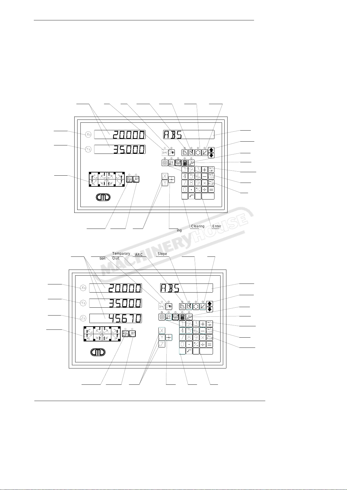
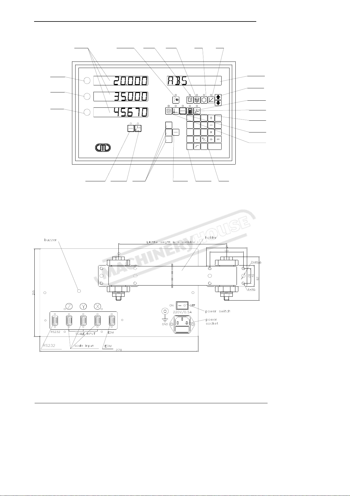
1.1 Front Panel.............................................................................................................3
1.2 Back Panel..............................................................................................................4
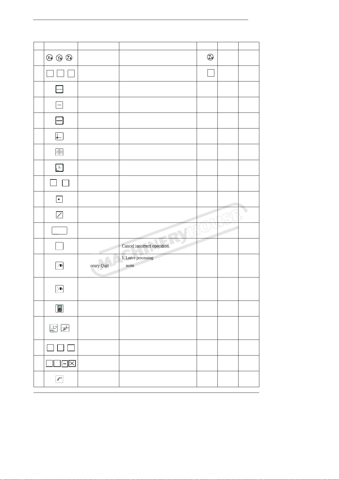
1.3 Description of Key Function..................................................................................5
1.4 Interface..................................................................................................................7
1.5 Coordinate System .................................................................................................8
Chapter 2. BASIC OPERATION............................................................................................9
2.1 Power on.................................................................................................................9
2.2 Zeroing...................................................................................................................9
2.3 Preset Data to Designated Axis............................................................................10
2.4 Toggle display unit between mm and inch...........................................................11
2.5 Mid-point Calculation..........................................................................................11
2.6 Set the Shrinkage Mode.......................................................................................12
2.7 Absolute / Incremental / 1000 groups SDM ........................................................13
2.8 Clear All SDM Datum..........................................................................................14
2.9 Search the Absolute Reference Point of Scale (RI) .............................................15
2.10 Clear the Error message .......................................................................................16
2.11 Lathe Function .....................................................................................................16
2.12 Filter display value...............................................................................................17
Chapter 3 1000 groups SDM coordinate...............................................................................18
3.1 Zeroing at the Current Point.................................................................................18
3.2 Preset datum of SDM Coordinate ........................................................................20
Chapter 4 SPECIAL FUNCTION.........................................................................................22
4.1 Bolt Hole Circle ...................................................................................................22
4.2 Bolt Hole Line......................................................................................................24
4.3 ARC Processing...................................................................................................26
4.4 Slope Processing..................................................................................................30
4.5 Auto Edge Detection............................................................................................33
Chapter 5. EDM....................................................................................................................35
5.1 Setting EDM Parameters......................................................................................36
5.2 EDM machining...................................................................................................37
5.2.1 Example for Mode 1 with Plus Depth..................................................................37
5.2.2 Example for Mode 1 with Minus Depth ..............................................................38
5.2.3 Example for Mode 2.............................................................................................40
5.2.4 Example for Mode 3.............................................................................................41
5.2.5 Example for Mode 4 with Minus Depth ..............................................................42
5.2.6 Example for Mode 6.............................................................................................44
5.2.7 Example for Mode 7.............................................................................................45
5.3 Combination of BHC: BHL and EDM Function .................................................47
Chapter 6 CALCULATOR FUNCTION ............................................................................49
6.1 Enter and exit Calculator Function ......................................................................49
6.2 Calculating Example............................................................................................49
6.3 Transferring the Calculated Results to Selected Axis..........................................49
6.4 Transferring the Current Display Value in Window to Calculator.......................50
Chapter 7 INITIAL SYSTEM SETTINGS...........................................................................51
7.1 Enter/Exit Initial System Settings........................................................................51

SW4000 USER’S MANUAL
2 VER5.13
7.2 Setting the type of DRO.......................................................................................52
7.3 Setting Positive Direction for Counter.................................................................52
7.4 Setting Linear Compensation...............................................................................53
7.5 Toggle Between R/D Display Mode....................................................................55
7.6 Setting Z axis Dial................................................................................................56
7.7 Setting the Resolution of Scale............................................................................57
7.8 Setting Relay Mode..............................................................................................58
7.9 Setting the EDM Mode ........................................................................................59
7.11 Enable / Disable ERROR Signal..........................................................................60
7.12 Setting Shrinkage Ratio........................................................................................61
7.13 Enable/Disable EDM Depth Compensation.........................................................61
7.14 Setting the Slope Machining Parameter...............................................................62
7.15 Setting Lathe Mode..............................................................................................63
7.16 Setting RI MODE.................................................................................................63
7.17 Enable/Disable Edge Detection............................................................................64
7.18 Toggle between Linear Scale and Rotary Encoder ..............................................65
7.19 Step Mode of ARC...............................................................................................65
7.20 Angle Display Mode............................................................................................66
7.21 Angle display type................................................................................................67
7.22 Load default setup................................................................................................67
Chapter 8 TROUBLES HOOTING ......................................................................................70

SW4000 USER’S MANUAL
VER5.13 3
Chapter 1 Brief Introduction
1.1 Front Panel
SW4000-2:
SW4000-3:.
Axis
Selection
INC/ABS
Switch SDM
Switch
ARC Type
Y-Zero
55 66 77 88
11 22 33 44
X-Zero
X/Y-window Lathe
Function Temparary
Quit
EnterCentrial
Finding Clearing
AC π
-1
N
O
ENTER
Shrinkage
RI
Finding
Inch/Metric
Switch
Calculator
Item
Selection
Shift
Slope
ARC BHC BHL
Message-
window
SW4000
ar
ar
Axis
Selection
INC/ABS
Switch SDM
Switch
ARC Type
Z-Zero
Y-Zero
55 66 77 88
11 22 33 44
X-Zero
X/Y/Z-
window Lathe
Function Temparary
Quit
EnterCentrial
Finding Clearing
AC π
-1
N
O
ENTER
Shrinkage
RI
Finding
Inch/Metric
Switch
Calculator
Item
Selection
Shift
Slope
ARC BHC BHL
Message-
window
SW4000
arar

SW4000 USER’S MANUAL
4 VER5.13
SW4000E:
1.2 Back Panel
SW4000
ar
ar
Y0
Z0
INC
ABS 0
999
X0
X
Y
Z
π
ENTERAC
Y
X
Z7
1
2
0
4
INCH
MM
RI
1
H
-1
Tan
98
5 6 -1
Cos
N
2 3
O
-1
Sin
-1
Axis
Selection
INC/ABS
Switch SDM
Switch
Z-Zero
Y-Zero
X-Zero
X/Y/Z-
window Temparary
Quit
Enter
Centrial
Finding Clearing
Shrinkage
RI Finding
Inch/Metric
Switch
Calculator
Item
Selection
Shift
EDM
RUN
EDM
DEEP BHC BHL
Message-
window

SW4000 USER’S MANUAL
VER5.13 5
1.3 Description of Key Function
KEY MARK KEY NAME FUNCTION SW4000-2
SW4000-3
SW4000E
1
X/Y/Z-Zero Zero selected axis. No
2
X
Y
Z
Axis Selection Select axis to operate. No Z
3
INCH
MM
Inch/Metric Switch Toggle display unit between metric and inch.
4
1
2
Center Finding Half a display value of an axis.
5
ABS
INC
ABS/IINC Switch Toggle between ABS/INC coordinate.
6
RI
RI Finding Find the origin of the linear scale.
7
Shrinkage Toggle between shrinkage and unshrinkage.
8
999
0
SDM Switch Second data memory.
9
0
─
9
Numeric Key Enter number.
10
.
Decimal Point Enter decimal point.
11
+-
+/- Sign Enter +/- sign.
12
ENTER
Enter Confirm operation.
13
AC
Clearing Cancel incorrect operation.
14
X
Y
Temporary Quit
1. Leave processing temporarily to return
normal display state.
2. Enter auto edge detect function.
X X
15
X
Y
Z
Temporary Quit
1. Leave processing temporarily to return
normal display state.
2. Enter auto edge detection.
X
16
Calculator Enter /quit calculating state.
17
N
O
-1
N
-1
Shift
1 Calculate inverse trigonometric unction in
calculating function.
2 Enter No. of SDM coordinate.
18
-1
sin
-1
cos
-1
tan
Trigonometric
Function
Calculate trigonometric or inverse
trigonometric.
19
+-
.
.
Add: Decrease:
Multiple: Divide
Operate adding: decreasing: multiplying:
dividing.
20
Radical Sign Square root or square.

SW4000 USER’S MANUAL
6 VER5.13
21
π
Circumference
Ratio Enter circumference ratio.
22
Equality Sign Make calculating result.
23
H
Set EDM Set parameters of EDM. X X
24
Start EDM Enter EDM processing. X X
25
BHC Process holes displayed equally on a circle.
26
BHL Process holes displayed equally on a line.
27
ARC Simple R cutting function X
28
SLOPE Process a slope. X
29
Y
X
+
Lathe Function Enter or exit lathe function. X X
30
X
+ Y
Z
Lathe Function Enter or exit lathe function. X X
31
Item Selection Stroll up or down to select.
Note: “X” indicates this model has no such a function.

SW4000 USER’S MANUAL
VER5.13 7
1.4 Interface
ALinear Scale Interface
1) 9PD Connector
2) 15PD Connector
3) 7Pin Connector
3RXD ORG
COLOR
NC
4
9
6
5
IN-
IN+
PIN NAME
2
3
1NC
5
4GND
NC
BLK
YEL
RED
ORG
BRW
BRW
COLOR
2NC
7FG
2
1
PIN
TXD
NC
NAME
5
6
4
3
+5V
RI
B
A
5 RI
1OV
4
3
1
2
B
A
+5V
0V
SHILD WIRE
YEL
RED
ORG
YEL
BLK
5
4
3
RI
B
A
1
2+5V
0V
ORG
YEL
BRW
BLK
RED
PIN NAME COLOR
PIN NAME COLOR
PIN NAME COLOR
RED
BLK
BRW
YEL
ORG
BRS232 Interface
CEDM Interface
COMMON
NORMAL CLOSE
NORMAL OPEN

SW4000 USER’S MANUAL
8 VER5.13
1.5 Coordinate System
SW4000 DRO is an instrument which can measure position of work piece when processing.
Coordinate system must be definite first for more efficiency and accuracy.
YZ
plane
XZ
plane
XY
plane
X
ZY
In horizontal plane, the X axis is parallel with the operator; Y axis is perpendicular to X axis. Z-axis is
perpendicular to horizontal plane. Positive direction of axis is set as the figure. It also can be changed as
customer.
The value of one point position is the distance relative to the origin of coordinate.
For a work-piece as Figure A, the value of each point position is as the Figure B when point O is the origin
of coordinate.
A
B
C
DE
o
H
G
F
X
F(-32,-8)
B(-32,8)
A(-18,18)
Y
H(18,18)
G(32,8)
E(18,-18)
C(-32,-8)
D(-18,-18)
Fig B

SW4000 USER’S MANUAL
VER5.13 9
Chapter 2 BASIC OPERATION
2.1 Power on
Function: Power on then SW4000 enter normal display state.
It can memorize the following parameter after power on.
A. The scale position where power off;
B. ABS/INC/SDM mode;
C. Shrinkage is enabled or disable;
D. Metric/Imperial mode;
The origin of the linear scale must be searched again if the scale is moved when power off.
Note: Normal display state
The state DRO automatically enters after on or exit from “STEUP”. In normal
display state, X window,Y window and Z window displays the current value of
X axis, Yaxis and Z axis separately. The message window displays “ABS”,
“INC” or “SDM XXX” (indicate the Number of SDM coordinate, with a range
of 000—999).When user switch among ABS/INC/SDM, MM/INCH or shrinkage / Un-shrinkage, DRO will not
leave this state. When you enter CALCULATOR function, input data to X (or Yor Z) axis, function of searching
the Reference point (RI) of the linear scale or special function (BHC: BHL:ARC: SLOPE PROCESSING and
EDM function): DRO is not in the normal display state.
2.2 Zeroing
Function: Zero the designated axis in normal display state. Zeroing is used to set the current point as datum
point.
Note: 1 The axis can’t be zeroed when DRO is in other states (for example: in the state of calculating function
or in special function). DRO should return normal display state;
2 The axes can be zeroed in ABS/INC/SDM states;
3 When zero in ABS coordinate, INC display value is cleared simultaneously. Zeroing in INC
coordinate has no effect on ABS and SDM display value.
4 Press the zero key of the same axis will cancel above zero operation
if the scale kept still after zero.
5 zero is means that set the current point as the origin point of current axis.
Example 1:Set the point O (as the figure illustrated) as datum
STEPS:
1) Return normal display state;
2) Move the machine table: and align the lathe tool with point O.
The DRO displays as the right figure.
3) Press to zero X axis,
0X
Y

SW4000 USER’S MANUAL
10 VER5.13
Press to zero Y axis.
2.3 Preset Data to designed axis
Function:Preset a value to current position for a designed axis in normal display state.
NOTES: 1 Axis can not be preset while the DRO is in other states (e.g. calculating function or special function).
DRO should return normal display state before presetting data.
2 Axis can be preset in ABS/INC/SDM state.
3 In SDM state, input mode “0” means that the display value is equal to the enter value; input mode
“1” means that the display value is equal to the negative of enter value.
4 The range of input value is that the minimum value to the maximum value which could be displayed
in the designated window.
Example: Machine the work-piece from the figure (a) to figure (b), and the plane C
is the datum and counting direction is right.
STEPS:
1. Move the machine table, and align the lathe tool to plane B.
2Return normal display state;
3Press X, “0” is flashing in X window, waiting for entering a data;
4Press 10+-in turn, which means the preset data is “-10”;
If incorrect value is inputted: press
AC
to cancel and input again;
NOTE: If in SDM state and SDM input mode is “1”, +-needn’t be inputted.
Otherwise +-must be inputted.
5. Press ENTER to confirm the data that your input and end
presetting it to X axis;
6. Moving the machine table until “-28.000” is displayed in X window.
Now it is the position of plane A.
7. Y axis, Z axis can be preset in the same way.

SW4000 USER’S MANUAL
VER5.13 11
2.4 Toggle display unit
between mm and inch
Function:Length can be displayed either in “mm” (metric) or “inch” (imperial). Display unit can be
toggled between mm and inch.
Example: Display value toggle from mm to inch
STEPS:
1. DRO returns normal display state. The LED of INCH is off, which
means the current unit is mm (metric);
2. Press
INCH
MM
, then the LED of INCH/mm is on, which means the
display unit is inch now.
3. It is invalid to toggle between mm and inch while axis is encoder.
NOTE: If in imperial, the LED of INCH is on; and in metric unit, the LED
of NCH is off.
2.5 Mid-point Calculation
Function:Set the center of work piece as datum by halving the displayed
value.
Example: Set the center of rectangle as datum as the right figure.
STEPS:
1. Place the work piece on the machine table, with line AB parallel with
X axis, line AD parallel to Y axis;
2. DRO returns normal display state, move machine table and align the
lathe tool with point A;
Press to zero X axis, press to zero Y axis;
3. Align lathe tool with point C by moving machine table;
Press
1
2
, Xin turn to halve the X axis display value;
Press
1
2
, Yin turn to halve the Y axis display value;

SW4000 USER’S MANUAL
12 VER5.13
4. Move the machine table until “0.000” is displayed in X
window and Y window. The position (where the lathe tool
is) is the work-piece’s center.
Note: 1. If you do other operation after axis half, please press
1
2
, will cancel above operation,
and X-axis display value return to normal.
2. It is invalid to mid-point calculation while axis is encoder.
2.6 Set the Shrinkage Mode
Function: With this function, you can process the mould tools according to the dimension of the finished
products without calculating dimension separately.
display value = actual value x shrink ratio.
STEPS:
A. unshrinkage shrinking
1. DRO returns normal display state;
2. Press and don’t release. The Y window
displays the current shrinkage ratio, the message
window displays “SURE AGN”, which means
you need to confirm once again.
3. Press ENTER to enter shrinkage state; press any
other key to return former state.
NOTE: I should not be released and press ENTER simultaneously to enter shrinkage state;
LED of shrinkage flashes in shrinkage mode;
II You can view the shrink ratio by making use of this function: press will display shrink ratio of Y
axis; Then press any key can return normal state;
III The signal light of shrink ratio will flicker while in shrinkage.
B. shrinkage unshrinking.
1. DRO returns normal display state;
2. Press , now DRO is in unshrinking mode, LED of shrinkage is off;
shrinkage
ratio

SW4000 USER’S MANUAL
VER5.13 13
2.7 Absolute / Incremental / 1000 groups SDM
Function: The SW4000 series DRO has 3 display modes: the absolute mode (ABS); the incremental mode
(INC) and 1000 groups Second Data Memory (SDM) with the range of 000 to 999.
1. Zero point of work-piece is set at the origin point of ABS coordinate;
2 The relative distance between datum of ABS and SDM remains unchanged when ABS datum is
changed.
3. If one point in ABS is zeroed, the point in INC is zeroed automatically; yet if one point in INC is
zeroed, the point in ABS will remain unchanged.
I. toggle amongABS/INC/SDM coordinate
These three display modes can be changed only in normal display state.
ABS INC Press
ABS
INC
;
INC ABS Press
ABS
INC
;
SDM INC Press
ABS
INC
to enter ABS or INC. If in ABS: press
ABS
INC
again.
SDM ABS Press
ABS
INC
to enterABS or INC. If in INC: press
ABS
INC
again.
INC SDM Press
999
0
ABS SDM Press
999
0
II. Set the new number of SDM in SDM mode
STEPS:
1. Enter SDM mode;
2. Press N
O
-1 (two axes DRO) or (three axes
DRO), message window flashes, waiting for
inputting a new number of SDM;
3. Enter a new number. for example, enter 666.
4. Confirm new SDM number.
Press N
O
-1 (two axes DRO) or (three axes DRO), then the message window stops
flashing and the number of SDM is changed to 666.
III: Increase/Decrease the SDM number
DRO return normal display state with the display mode SDM, press to decrease the number
of SDM by 1; press to increase the number of SDM by 1.
Example: If the current SDM number is 777, and the message window displays “SDM 777”,
press , then the message window will display “SDM 776”, which means the

SW4000 USER’S MANUAL
14 VER5.13
current SDM number is 776.
If the current SDM number is 777 and the message window displays “SDM 777”,
press , then the message window will displays “SDM
778”, which means the current SDM number is 778.
If a work-piece as the figure is to be machined where the datum plane is
plane E, the coordinate can be set as the following steps:
1. Return normal display state with ABS coordinate;
2. Move the machine table until the lathe tool is aligned with
plane E, then zero X axis;
3. Move the machine table until the lathe tool is aligned with the plane
D. Change SDM number to SDM 000, and press to zero X
axis. Then the NO.000 SDM coordinate’s datum is set at plane D.
4. Move the machine table until the lathe tool is aligned with plane C,
press to change SDM to SDM 001, and then press to zero
X axis, and the SDM 001 with the datum plane C is set.
5. Move the machine table until the lathe tool touches the plane B, the
DRO will display as the right.
6: Move the machine table until the lathe tool touches the plane A, the
DRO will display as the right.
2.8 ClearAll SDM Datum
Function:Clear the Datum of all SDM 0 - 999. After clearing, the display value in SDM coordinate is
equal to the value in ABS coordinate.
STEPS:
1. Return normal display state;
2. Press
ABS
INC
and
AC
simultaneously for 2 seconds, and the message window displays “CLS
SDM” and flashes, which means it is clearing now. About ten seconds later, the clearing is
completed and “CLS OK” is displayed in message window temporary and DRO return normal
display state.
C
AB D E

SW4000 USER’S MANUAL
VER5.13 15
2.9 Search the Absolute Reference Point of Scale (RI)
Function: An absolute datum should be set when a work-piece is machined. There are two cases:
When the machine table is going in high speed, the machine
table can’t stop immediately but continue going further because
of inertia when power is off suddenly. There will be distance ∆L
between the actual position and the position in the DRO
memorize. That is to say the display value is not the actual value
of the position when power is on again.
If the machine table is moved without intention when DRO is
off.
How to restore the preset ABS and correct display value?
These questions can be solved easily with this function of search RI.
STEPS:
1. DRO is set in ABS coordinate.
2. Press RI , then the message window displays “SELAXIS”;
3. Select the axis which need search RI. For instance: select Y axis, then
press Y. “FD.Y REF” is displayed in message window, and Y
window flashes.
4. Move the machine table. The buzzer sounds when RI is searched, then
Y window stops flashing and displays the value of the current
position, the DRO returns normal display state.
In the course of searching, press
AC
to quit this operation.
The machine table is moved when DRO is off. How to restore the former absolute ABS coordinate
and correct display value?
Take SW4000-2 as an example.
STEPS:
1)This operation (searching the absolute origin point of the
scale) is necessary when a linear scale is installed or the
default parameter is loaded. Or the ABS coordinate would
not be restored.
2)Set the point O as the datum of ABS. (Move the machine
Y
0X
0
A
X
Y
0X
Y

SW4000 USER’S MANUAL
16 VER5.13
3)table until the lathe tool is aligned with point O, and zero
the X axis, Y axis)
3) The machine table is moved when power is off;
4) Power on, switch to ABS coordinate. The DRO maybe
displays as the right.
5) Search the RI of X axis and Y axis. After RI is found, the
ABS coordinate is restored.
6) Align the lathe tool with point O, “0.000” is displayed in
X window and Y window, which means the point O is the
origin and the ABS coordinate is restored.
NOTE:
The linear scale has a RI every 50 mm. For the sake of search identical RI, move the scale around the red
mark “ ” to search RI.△
△△
△
Setup correct RI mode is a premise.
2.10 Clear the Error message
If ERROR message is enabled, the message window will display “E1” if the signal of phase A and
phase B of the linear scale changes at the same time; the message window will display “E2” if the linear
scale runs too fast; the window will display “E3” if these two conditions occur simultaneously. When error
information appears, the display value has an error of 1-2 count. So users need search RI to restore ABS
coordinate. If you think that doesn’t affect your work, press
AC
to clear error message and continue your
work. .
Example : When signal of A phase and B phase is same in Y
axis the window displays as the right figure.
Press
AC
to clear the error information. Y window
displays the value, but it is error. The difference between the
display value and the true value is about 1- 2 times of
resolution. For instance, the resolution of scale is 5µm; the
difference is 5-10µm.
2.11 Lathe Function
As the right figure, if two scales are installed
in one axis, the position of the work-piece should
be the sum of these two values (X+Y) in this

SW4000 USER’S MANUAL
VER5.13 17
direction. It is called lathe function.
A. lathe mode 0: normal display (the lathe
function is disabled).
B. lathe mode 1: X window value = the value of X axis position + the value of Y axis position.
C. lathe mode 2: X window value = the value of X axis position + the value of Z axis position.
STEPS:
1. Set the lathe mode in initial system settings;
2. In normal display state press (three axes display) or
Y
X
+
(two axes display) to enter lathe
function. Then the LED of the lathe function will be on (If the lathe mode is 0, the lathe function is
disabled and the LED is off);
3. In lathe state, press (three axes display) or Y
X+ (two axes display) to exit the lathe function:
and the LED turns off.
A. If in normal display state: the value of the position is as the
right.
B. In lathe mode 1, the DRO will display as the following:
X window display value = value of X axis position +
value of Y axis position
C. In lathe mode 2, the DRO will display as the
following:
X window display value = value of X axis position +
value of Z axis position
2.12 Filter display value
When machine a work-piece by grinder, the display value varies quickly due to the vibration of
grinder. User can’t see display value clearly. SW4000 series DRO provides display value filter function to
disable the quake change of display value.
STEP:
1) Enter display value filter function.
In normal display state, press N
O
-1 and
ENTER
simultaneously, enter display value filter function.
2) Exit display value filter function.
Press N
O
-1 , exit display value filter function.

SW4000 USER’S MANUAL
18 VER5.13
Chapter 3 1000 groups SDM coordinate
SW4000 has three display modes: the absolute mode (ABS), the incremental mode (INC) and the
1000 groups second data memory (SDM 0—SDM999).
ABS datum of the work-piece is set at the beginning of the processing and the 1000 group SDM is
set relative to ABS coordinate.
1000 group SDM coordinate can be divided into several segments, and every segment stores data of
one work-piece. If one segment has 20 groups SDM coordinate, DRO can be divided into 50 segments
and can store data of 50 work-pieces.
SDM 000 ------ SDM 019 data of the first work-piece
SDM 020 ------ SDM 039 data of the second work-piece
SDM 040 ------ SDM 059 data of the third work-piece
……
SDM 960 ------ SDM 979 data of 49th work-piece
SDM 980 ------ SDM 999 data of 50th work-piece
Example:The ABS datum is the center point O,
the point E, F, G, H needed processing are set
as datum of SDM 000 —SDM 003.
Two ways to set SDM coordinates:
1) Zeroing at the current point.
2) Presetting datum of SDM coordinate.
3.1 Zeroing at the Current Point
At first set the center point of the work-piece as the origin of the ABS, then align the lathe tool with
point E, F, G, H by moving the machine table and zero them. It is the position to process where the “0.00”
appears in X window, Y window by moving the machine table whether in ABS or in SDM coordinate.
STEPS:
1. Set the center of rectangular point O as the datum of ABS
Make line AB parallel with X axis: line AD parallel with Y axis.
When position lathe tool to point O
Zero X axis and Y axis in SDM 000;
Zero X axis and Y axis in SDM 001;
Zero X axis and Y axis in SDM 002;
Zero X axis and Y axis in SDM 003;
2. Set the point E as the datum of SDM 000.
SDM 000: align the lathe tool with point E and zero
X axis, Y axis. DRO displays as the right.
Y
O
X
C
O
D
A
E
H
G
F

SW4000 USER’S MANUAL
VER5.13 19
Press ,
3. Set the point F as the datum of SDM 001.
In SDM 001 and align the lathe tool with point F,
then zero X axis, Y axis. DRO displays as the right:
Press ,
4. Set the point G as the origin of SDM 002.
In SDM 002, align the lathe tool with point G, and
zero X axis, Y axis. DRO displays as the right.
Press ,
5. Set the point H as the origin of SDM 003.
In SDM 003, align the lathe tool with point H, and
zero X axis, Y axis. DRO displays as the right.
Press , ;
6. Machine the work-piece according to the preset SDM coordinate;
7. Machine another work-piece according to the same blueprint. You only need set the center point
as the datum of ABS. It is not necessary to set SDM coordinate again, as SDM can be set
automatically. Point E, F, G, and H is the zero point of SDM 000, SDM 001, SDM 002, and SDM
F
G
H
E
Table of contents
Other MachineryHouse Industrial Equipment manuals
Popular Industrial Equipment manuals by other brands

nbs
nbs Citadel 2.0 Series Installation, operation and maintenance manual

Zehnder Rittling
Zehnder Rittling 7505/N3 quick start guide

DUSTLESS BLASTING
DUSTLESS BLASTING DB350 Mobile XS user manual

Coloplast
Coloplast Assura EasiClose Instructions for use

Newport
Newport GTS-V Series user manual

Graphic Whizard
Graphic Whizard PT CR607 Operator's manual

Kellfri
Kellfri 32-S200 operating instructions

ABB
ABB HT845551 Operation manual

R.V.R. Elettronica
R.V.R. Elettronica RXRL-NV Technical manual

Kooltronic
Kooltronic KNHX38 Series Operator's manual

flamco
flamco Logotherm LogoComfort 500 Installation and servicing instruction

Ceriotti
Ceriotti FX3800 Assembly instructions