Instron SI Series User manual

Appendix A and Drawings
DUTCHESS COMMUNITY COLLEGE
Materials Testing Lab
RFB-DCC-08-2016
Appendix A
www.instron.com
Industrial Products Group
SI-Series Impact
Testing Machine
Pre-Installation Manual
M47-16824-EN Revision A
The difference is measurable
®
A
PPENDIX
A
CLOUDED
SECTIONS
INDICATE
INFORMATION
RELATED TO
CONTRACTOR
RESPONSIBILTY

11
Purpose
Product Support: www.instron.com
Figure 1. Impact testing system components - non-motorized models.
12
6
9
5
4
2
3
1. Lifting Eye
2. Safety Catch
3. Stop Pin
4. Operating Lever
5. Pointer
6. Pusher Arm
7. Pendulum Shaft
8. Pendulum Head
9. Upper Dial
10. Lower Dial
11. Base
12. Anvil Assembly
13. Clean-Out Hole
14. Charpy Anvil
15. Tensile Anvil or Charpy Support
16. Clamping Screw (Izod Vise)
17. Wooden Safety Block
18. Shrouds
1
10
14
15
16
17
13
11
8
Pendulum in
high latch
position.
Pendulum in
low latch
position.
7
18
Anvil with shrouds in place.
A
PPENDIX
A

15
Customer’s responsibilities
Product Support: www.instron.com
Customer’s responsibilities
It is the customer’s responsibility to ensure that the proper foundation is installed, the machine is in place
and secured to the foundation, all required support services (i.e. power, air, and/or water supplies,
telephone line, etc.) are available, and that all necessary checks are made prior to installing the testing
system. These services and checks are described below.
Site preparation
Proper site preparation is imperative so that the testing system operates in accordance with its
specifications and provides accurate test results. The customer must ensure that the site requirements
are satisfied prior to scheduling an installation appointment with Instron Service. These site
requirements are described in this manual under Chapter 3, “Pre-Installation (Pre-Shipment
Arrival)” and Chapter 4, “Pre-Installation (Shipment Arrival)”. Always verify your machine’s specific
model when referencing any information in this manual; refer to the Instron sales order or quote (see
customer copies), or the serial number tag located on the machine frame.
Handling and transporting
Unless specifically arranged otherwise, it is the customer’s responsibility to arrange the off-loading,
unpacking and moving of the testing system to the final installation location. Refer to “Moving the
machine” in Chapter 4 for details on handling and transporting your system to its final location.
Upon special arrangements, an Instron service engineer can supervise the off-loading and transportation
of the machine frame to its final installation location. Contact Instron’s service department or your local
Instron office for additional information on this service. Refer to “Product support” on page 12 for
Instron’s contact information.
Insurance and safety
Under Instron’s standard contract, the shipping terms are Ex-Works (or FOB Factory), meaning ownership
and liability for the testing system transfers to the customer at Instron’s loading dock. Unless other
shipping terms are specified in a purchase order, which Instron does not dispute, the Ex-Works shipping
terms apply. Under these terms, the customer is responsible for securing the applicable transit insurance
on the shipment and arranging safe transport to the final destination. Arrangements can be made
through Instron to secure insurance cover and shipping, at the customer’s expense.
When transporting a machine frame within your own premises, you are responsible for its safe transport.
As stated under “Handling and Transporting” above, you can arrange for an Instron service engineer to
supervise the off-loading and transportation of the machine frame to its final installation location.
A
PPENDIX
A

Chapter 1: Introduction
16 M47-16824-EN
Instron’s responsibilities
Instron’s standard contract requires Instron to provide the necessary services to ensure that your testing
system operates accurately. These services are described below.
Additional services and equipment may be negotiated with Instron, but these additional services must be
mutually agreed upon and specifically described in your purchase order.
Insurance
Under Instron’s standard contract, the shipping terms are Ex-Works (or FOB Factory), meaning ownership
and liability for the testing system transfers to the customer at Instron’s loading dock. Unless other
shipping terms are specified in a purchase order, which Instron does not dispute, the Ex-Works shipping
terms apply. Under these terms, Instron is responsible for insurance cover while the testing system is in
the factory up until it reaches the loading dock for shipping.
Installation
Installation is included with the purchase of the system. After the site is prepared, the machine frame is
in place on its foundation, and all components are on site, installation by Instron will cover complete
setup of the testing instrument and digital indicator (when purchased), including all electrical hookups.
Documentation
Instron provides all documentation required to operate the system, including manuals for the machine
frame and any required software applications.
Additional copies are available and can be ordered through any Instron sales office.
A
PPENDIX
A
Chapter 2: Specifications
18 M47-16824-EN
System physical dimensions
System packaging dimensions
Table 5. Dimensions of standard Impact machine frames.
Machine Model Overall Height1Overall Area2(W x D) Net Weight3
SI-1C3, SI-1K3
1820 mm
71.5 in
710 x 485 mm
28 x 19 in
450 kgs
985 lbs
1. Height with pendulum latched in highest latch position.
2. Dimensions are of the widest and deepest portion(s) of the equipment For the machine this does not account for
pendulum swing. For the safety guard this does include the electrical box but does not account for clearance
needed to open guard doors or electrical box door.
3. Does not include pendulum.
Table 6. Pendulum weights (at striker).
Machine Model Pendulum Net Weight
SI-1C3, SI-1K3
Heavy 30.239 kgs (66.666 lbs)
Table 7. Typical shipping dimensions for standard Impact systems - all models.
Machine Model
Approximate Crate Dimensions
(L x W x H)
Approx. Weight of Crated
Machine
SI-1C3, SI-1K3
915 x 1040 x 1575 mm (36 x 41 x 62 in) 650 kgs (1430 lbs)
A
PPENDIX
A

19
Chapter 3
Site Preparation
•
Requirement checklist . . . . . . . . . . . . . . . . . . . . . . . . . . . . . . . . . . . . . . . . . . . . . . . . . . . . . 19
•
Component placement and operator safety . . . . . . . . . . . . . . . . . . . . . . . . . . . . . . . . . . . . 21
•
Foundation. . . . . . . . . . . . . . . . . . . . . . . . . . . . . . . . . . . . . . . . . . . . . . . . . . . . . . . . . . . . . . . 22
•
Power requirements . . . . . . . . . . . . . . . . . . . . . . . . . . . . . . . . . . . . . . . . . . . . . . . . . . . . . . . 24
•
Telephone and network . . . . . . . . . . . . . . . . . . . . . . . . . . . . . . . . . . . . . . . . . . . . . . . . . . . . 24
•
Additional utilities . . . . . . . . . . . . . . . . . . . . . . . . . . . . . . . . . . . . . . . . . . . . . . . . . . . . . . . . . 24
•
Ceiling clearance. . . . . . . . . . . . . . . . . . . . . . . . . . . . . . . . . . . . . . . . . . . . . . . . . . . . . . . . . . 24
•
Environmental conditions. . . . . . . . . . . . . . . . . . . . . . . . . . . . . . . . . . . . . . . . . . . . . . . . . . . 24
Requirement checklist
Before the SI-Series Impact System arrives at your facility, it is important that the site be adequately
prepared in order to avoid unnecessary delays in machine placement and installation. Also to ensure that
the system operates without interference from various environmental conditions (i.e. excess building
vibrations or extreme temperature and humidity levels).
Below is a reference checklist designed to aid the customer in preparing the testing system(s) installation
site. Each item of the checklist is discussed in more detail in the following sections. Please use and refer
to this checklist to complete each item.
Determine the specific placement of components at the installation site so that there is an
appropriate amount of room to access system and for a machine safety zone. See “Component
placement and operator safety” on page 21.
Prepare appropriate foundation.* See “Foundation” on page 22.
Provide appropriate electrical power for system components. See “Power requirements” on
page 24.
Provide telephone and optional network lines to the installation site. See “Telephone and
network” on page 24.
Provide any additional utilities to the installation site (i.e. air for pneumatic grips, etc.). See
“Additional utilities” on page 24.
Ensure that the ceiling clearance of the customer facility and installation site is sufficient for
movement of system. See “Ceiling clearance” on page 24.
Ensure that the environmental conditions of the installation site are appropriate for the system. See
“Environmental conditions” on page 24.
* Instron is not responsible for foundation recommendations. This should be reviewed with a certified
civil engineer.
A
PPENDIX
A
21
Requirement checklist
Product Support: www.instron.com
Component placement and operator safety
All system components must be placed so that they can be easily accessed for service, maintenance and
calibration. Operator and personnel safety must also be considered when determining placement of the
SI-Series Impact system.
Accessibility
The recommended guideline is to have a 915 mm (36 in) clearance behind the machine. For
recommended clearances on each side of the machine, refer to “Machine safety zone”.
Machine safety zone
Machine safety zone refers to the area around the machine, particularly the areas on each side of the
machine, that should be observed for personnel safety. Operators, as well as other personnel in the
machine’s testing area, should be aware of this machine safety zone. This area should be very well
marked and observed at all times. Figure 2 details this safety zone. It also shows placement of the
optional safety guard or a customer supplied safety guard.
Warning
Only one operator should be performing tests at any given time. It is very unsafe to have
more than one person installing specimens and performing tests. Access to the front of the
machine should be limited solely to that of the test operator.
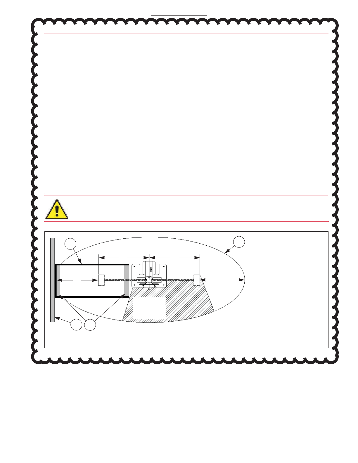
Figure 2. Overhead view of machine safety zone of non-motorized models.
Operator
Work
Space
1. Optional Safety Guard
2. Perimeter of Machine
Safety Zone
3. Floor Plates
4. Wall
A. Pendulum Swing Area -
930 mm (36.5 in) radius
B. Swing Clearance -
915 mm (36 in)
12
43
A A
BB
Drawing not to scale.
A
PPENDIX
A

Chapter 3: Site Preparation
22 M47-16824-EN
Foundation
Concrete foundation - recommended
The following is our recommendation for the foundation of your SI-Series Impact machine. This follows
closely with the recommended NIST practice. This recommended practice has been included in Appendix
A. Please refer to Appendix A for the NIST Recommended Practice for Machine Installation from the
October 2000 revision of “Installing, Maintaining, and Verifying your Charpy Impact Machine”.
The foundation for an impact machine is of critical importance for accurate test results. Energy loss
through absorption by the foundation must be kept to a minimum. Both ASTM E 23 and BS EN 10 045
specifications require that the foundation must be a minimum of 40 times the mass of the pendulum.
Our recommendations to meet this are shown in Table 8.
Tie down bolts must be securely embedded in the concrete and protrude 150 mm (6 in) above the
surface of the foundation. Tie down bolts can be J-bolts, T-bolts or similar anchor bolts. The
recommended bolt length is listed in Table 8. Four bolts are required, but are not provided with the
machine. J-bolts can be purchased separately, see Table 8 for Instron part numbers.
Leveling the machine requires three steel plates for placement under the leveling screws in the machine
base during installation. The plates should be approximately 75 x 75 x 6 mm (3 x 3 x 0.25 in).
See Figure 3 for tie down bolt and leveling screw locations.
Table 8. Foundation and tie down bolt recommendations.
Machine Model SI-1C3, SI-1K3
Foundation Area (Width x Depth)
1525 x 915 mm (60 x 36 in)
Foundation Thickness
(Dimension C of Figure 3) 460 mm (18 in)
Concrete Volume
0.64 m3(22.5 ft3)
Recommended Tie Down Bolt Length
380 mm (15 in)
Recommended Tie Down Bolt Extension Above Floor
(Dimension B of
Figure 3
)150 mm (6 in)
Instron Tie Down Bolt, T-bolts, 4 supplied when purchased
•Part Number
W-3573
•Bolt Length
(Dimension A of
Figure 3
)467 mm (18.375 in)
•Bolt Thread Size
0.875 in - 9
•Recommended Tightening Torque
407 N-m (300 ft-lbs)
A
PPENDIX
A
***** NIST Installation practices are not required for this project. *****
- Inertia base foundation is not required, equipment will sit on existing slab.
- Contractor is responsible for installation of J bolts before equipment arrives.
- Installation of J bolts will require removal of some slab material and in fill with high
strength epoxy or grout in order to install J-bolts of recommended size and depth.

23
Requirement checklist
Product Support: www.instron.com
Steel plate foundation
Where our recommended concrete foundation is not possible, a steel plate may be used to secure the
machine to the floor. A steel plate that is not less than 40 times the mass of the pendulum should be
used (refer to Table 6 on page 18 for the pendulum weight of your machine). To meet this criteria, the
steel plate can be the same dimensions as the concrete pad mentioned above (see Figure 3), but with a
thickness of 115 mm (4.5 in). The plate should be drilled and tapped with 0.875 in - 9 threads that are
32 mm (1.25 in) deep. The steel plate must be level per the requirements listed under “Leveling the
machine” on page 28. If it is necessary to grout, grout should only be placed between the floor and the
steel plate. Do not place grout between the steel plate and the machine base. Bolt the machine to the
steel plate using grade 8, or better, bolts. The steel plate must be bolted to the floor as well. The
mounting method used (shield, J-bolt, etc.) must have a minimum pull-out load equal to the tensile
strength of the mounting bolt used. The minimum bolt size recommended is 0.875 in diameter. Consult
a foundation expert or civil engineer for further foundation recommendations.
Figure 3. Foundation layout dimensions.
380 mm
(15 in)
485mm(19in)
610 mm (24 in)
710 mm (28 in)
Leveling screws
(0.5 - 13)
three locations
Tie down holes
(25 mm (1 in))
four locations
AB
C
See Table 8 for dimensions A, B and C.
20 mm (0.75 in)
63.5 mm (2.5 in)
355 mm
(14 in)
A
PPENDIX
A

Chapter 3: Site Preparation
24 M47-16824-EN
Power requirements
For non-motorized models (SI-1C3 and SI-1K3 models), no electrical power is needed to operate the
impact machine. If a digital indicator or data acquisition system is purchased with the system, it will
require power. Refer to its separate manual.
Telephone and network
Ensure that a telephone line is located within the general testing area. This enables the user to contact
Instron’s service department directly from the testing area so the user can perform the instructions
provided and resolve the situation while on the telephone with the service representative. This facilitates
resolving issues in a timely manner and reduces the number of repeated phone calls on the same
problem.
It is also suggested that network drops, or digital phone lines, be within the general testing area. Instron’s
goal is to provide remote diagnostics in order to resolve system issues. Having a network drop or digital
phone line available will enable an Instron service representative to dial into the testing system’s
computer to diagnose and resolve problems more efficiently. Including the network or digital lines in your
initial site preparation will facilitate adding this function if it becomes necessary in the future. Do not
connect the computer to the network until instructed to do so by Instron Service personnel.
Additional utilities
Depending on the system purchased and the customer’s requirements, the customer may need to
provide other utilities to the installation site; in addition to the main electrical power supply.
These additional utilities may include: cables for network connections; and/or direct phone line for
modem connection (Internet access and phone support).
Ceiling clearance
Ensure that there is adequate ceiling clearance so that the machine can be easily placed in its testing
location. Take into consideration how you will be transporting the machine (by forklift or crane, for
instance) and ensure that the ceiling height can accommodate your mode of transportation.
Environmental conditions
Ensure that the testing site meets the standards described under “Environmental conditions” on
page 17.
A
PPENDIX
A

25
Chapter 4
Shipment Arrival
•
Requirement checklist . . . . . . . . . . . . . . . . . . . . . . . . . . . . . . . . . . . . . . . . . . . . . . . . . . . . . 25
•
Receiving . . . . . . . . . . . . . . . . . . . . . . . . . . . . . . . . . . . . . . . . . . . . . . . . . . . . . . . . . . . . . . . . 25
•
Uncrating . . . . . . . . . . . . . . . . . . . . . . . . . . . . . . . . . . . . . . . . . . . . . . . . . . . . . . . . . . . . . . . . 26
•
Moving the machine . . . . . . . . . . . . . . . . . . . . . . . . . . . . . . . . . . . . . . . . . . . . . . . . . . . . . . . 26
•
Leveling the machine . . . . . . . . . . . . . . . . . . . . . . . . . . . . . . . . . . . . . . . . . . . . . . . . . . . . . . 28
•
System preparation. . . . . . . . . . . . . . . . . . . . . . . . . . . . . . . . . . . . . . . . . . . . . . . . . . . . . . . . 30
•
Preparing for service visit . . . . . . . . . . . . . . . . . . . . . . . . . . . . . . . . . . . . . . . . . . . . . . . . . . . 30
Requirement checklist
Once the testing system arrives at the customer’s site, the customer must also complete the following
before arrival of the Instron service engineer:
Receive the system. See “Receiving” on page 25.
Uncrate the system. See “Uncrating” on page 26.
Move the machine frame and all additional system components to the installation area. Do not
unpack system parts unless directed to do so in these instructions. See “Moving the machine” on
page 26.
Level the machine frame and secure the frame to its foundation. See “Leveling the machine” on
page 28.
Complete system preparations. See “System preparation” on page 30.
Prepare for visit from the Instron service engineer to complete installation. See “Preparing for
service visit” on page 30.
Receiving
The machine should arrive at the customer’s site in a single crate. A packing list is attached to the crate
and is enclosed in an adhesive backed package labeled “Packing List Enclosed”. Refer to Table 7 on
page 18 for typical crate dimensions and weights.
Any safety guards will be packed in a separate crate.
When the machine is received, visually check for damage to crating that may have occurred during
shipment. If damage is visible, check the contents of the crate for damage to parts. Notify both the
common carrier and Instron immediately to report any damage.
A
PPENDIX
A

Chapter 4: Shipment Arrival
26 M47-16824-EN
Uncrating
Impact testing systems are carefully crated at the factory to minimize the possibility of damage during
transportation. To prepare the machine for shipment, the following are performed:
•
The pendulum assembly is removed from the machine.
•
Strikers are removed from pendulums.
•
Shrouds are removed from the anvil assembly.
•
Unpainted and blackened components of the machine are treated with a rust inhibiting compound.
These components include: the bottom of the base, strikers, and inside the pendulum head. This
rust inhibitor should be removed from those components. Use either a citrus-based or solvent-based
degreaser to remove the rust inhibitor. If using a solvent-based degreaser, care must be taken
around any electronic components and cables to avoid damaging them. Solvent-based degreasers
can cause damage to plastics (i.e. circuit boards, etc.). Once the rust inhibitor is removed, the
unpainted and blackened components can be lubricated with a light weight machine oil to prevent
corrosion.
Once the machine frame is prepared for shipment, it is placed on a heavy-duty wooden skid and secured
to the skid with metal banding.
Perform the following to uncrate the system. Be sure to avoid damaging the system while uncrating.
•
Remove the crating and packing material from the machine and its components.
•
Verify the content of your shipment against the packing list provided. Retain all packing materials
until the system is satisfactorily installed and all parts, assemblies and accessories have been
located.
•
Notify Instron and the common carrier immediately if there are any discrepancies.
Moving the machine
Before you begin
Before moving the machine ensure that:
•
The final operating site is properly set up. Review all information in Chapter 3, in particular
“Foundation” on page 22 and “Power requirements” on page 24.
•
Your equipment operators have the appropriate licenses and have complied with your local safety
standards (i.e. the appropriate training required by OSHA in the U.S.).
•
At the final site location, there is adequate clearance between the ceiling and the top of the machine
frame, including clearance for lifting the frame via a forklift or crane.
•
There are no loose accessories on the shipping skid.
•
The frame and forklift (or crane) can fit through all doorways, halls, elevators or stairs from the
shipping dock to its final site location. If you move the machine frame while it is still crated, refer to
the crated dimensions listed in Table 7 on page 18. If you move the machine frame without the
crating, refer to the machine dimensions listed in Table 5 on page 18.
•
The floors from the shipping dock to the final site location have sufficient support for the weight of
the machine frame and forklift (or crane) combined.
•
You have adequate packaging materials to protect the machine frame when moving or relocating it to
another site. Contact Instron Professional Services to determine the appropriate packaging
requirements for your model type.
A
PPENDIX
A
27
Moving the machine
Product Support: www.instron.com
Equipment required
The following equipment is necessary to move the machine.
•
Hoist, overhead crane or fork truck
•
A sling that is appropriately rated for the weight of the machine
Warning
Recommended procedure
It is recommended that at least two adults be present when moving the machine. Non-motorized models
(SI-1C3 and SI-1K3) must be lifted by the supplied lifting eye.
1. Cut and remove the metal banding that secures the machine frame to the wooden skid.
a. Cut the bands and/or shrink wrap that holds the pendulum to the skid and remove the pendulum
from the skid.
b. Remove the box of accessories from the skid.
2. Position the lifting equipment:
a. W
When using a hoist or crane:
Place the sling through the eyebolt on top of the machine frame.
Attach the ends of the sling to the hoist or crane.
b. W
When using a fork truck:
Place the sling through the eyebolt on top of the machine frame. Attach
the ends of the sling to the forks of the fork truck. Be sure the sling is S
SECURELY ATTACHED
to
the forks. For added security, a “C-clamp” can be placed on each fork in front of the sling to keep
the sling from sliding off the fork. The forks must also be level or tilted back.
Warning
3. Carefully lift the machine from the skid and slowly move it to the desired location. Note that the
machine will not hang evenly when it is lifted. The machine will tip forward and cause the front of the
base to tip down.
4. Ensure the three 6 mm (0.25 in) thick steel plates are in the appropriate position for leveling the
machine base (see “Foundation” on page 22).
5. Place the machine base on the foundation over the steel plates.
6. Level the machine, see “Leveling the machine” on page 28.
Only experienced operators should run the crane or fork truck.
If the forks are tilted forward beyond level, this may allow the load to shift forcing the
C-clamps to carry the full machine weight. This can cause one or both of the C-clamps to
be ejected forcefully from their forks and become projectiles.
A
PPENDIX
A

Chapter 4: Shipment Arrival
28 M47-16824-EN
Leveling the machine
It is necessary to level the machine. The accuracy of the machine depends upon the precision of the
leveling.
Equipment needed
The following equipment is necessary to level the machine.
•
Non-shrinking grout, refer to Table 9 for some recommended grout brands; their equivalents may
also be used.
•
A machinist level, approximately 600 mm (24 in) or 900 mm (36 in) long.
Procedure
Perform the following to level the machine:
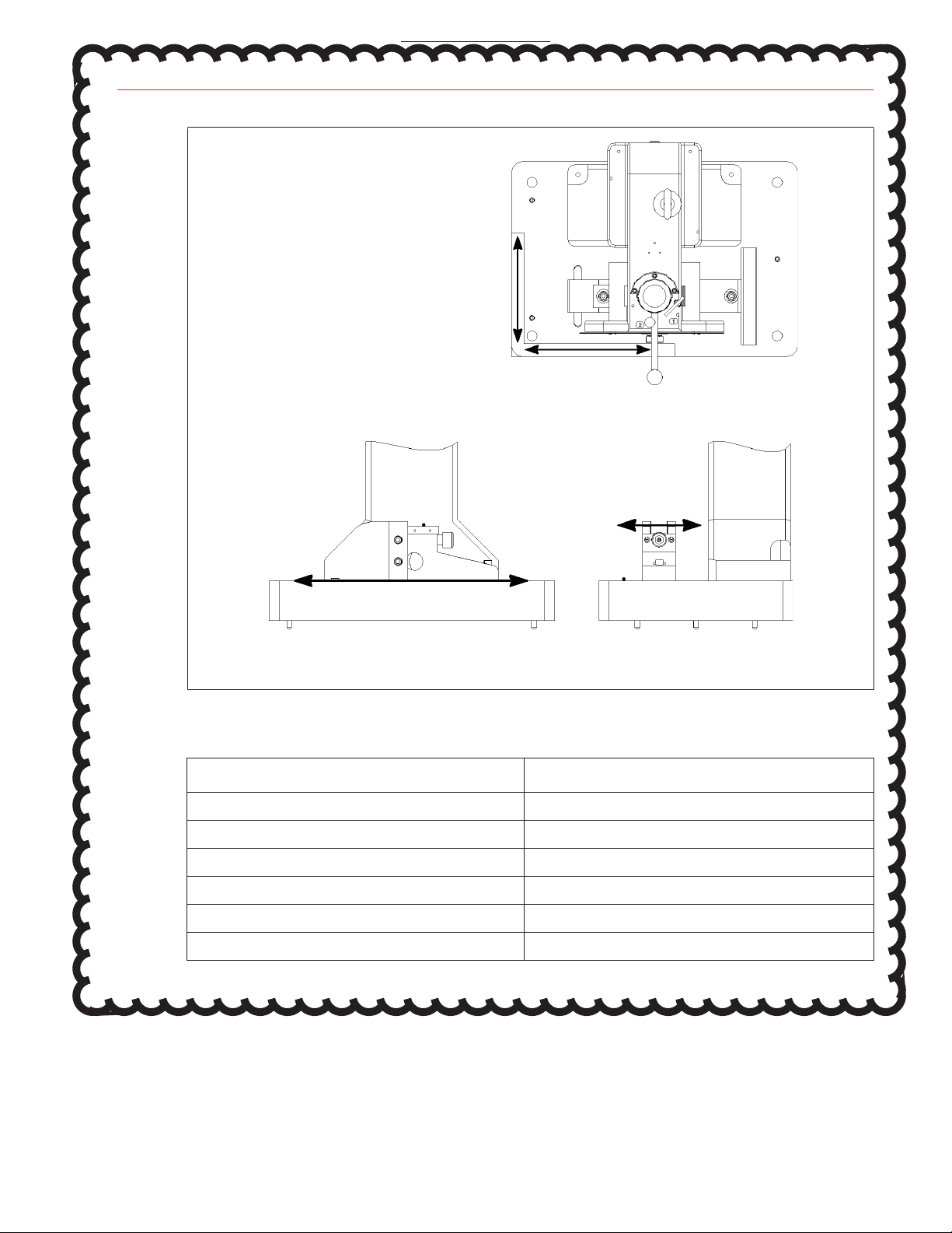
1. L
Level the machine to within 0.25 mm/m (0.003 in/ft) in both directions by adjusting the leveling
screws and using the machinist level as follows:
a. For SI-1M machines, any part of the base surface can be used as the level surface.
b. For most other machines, an unpainted area is left on the base for this purpose, see V
View A
Figure 4.
c. Older or reconditioned machines may not have this unpainted area. For these machines, the
following surfaces can be used as the level surface, see V
View B
of Figure 4:
•
Use the machine base for the line parallel to the plane of the pendulum swing.
•
Use the Charpy specimen supports for the line perpendicular to the plane of the pendulum
swing.
2. After the leveling screws are adjusted, snug the foundation bolts, but do not tighten them completely.
3. Fill the space between the bottom of the base of the impact machine and the top of the concrete pad
with a non-shrinking grout. Make sure that the grout flows under the machine to hold the bearing
plates in place under the leveling screws. The grout should completely seal around the crevice
between machine base and pad.
4. When the grout has set, loosen the leveling screws, and then tighten the foundation bolts in a criss-
cross pattern in small steps (68 N-m (50 ft-lbs)) until the appropriate torque is reached for your grade
of bolt; for bolts purchased from Instron, see Table 8 on page 22. Keep a record of what grade of
bolt is used and the torque required, as the torque of the bolts must be checked annually as part of
machine verification/inspection.
5. Check the level after the bolts are tightened to make sure that it is still within the tolerance stated
above.
For ease of spreading the grout, a gap of 20 mm (0.75 in) is recommended between the bottom of the
machine base and the top of the foundation.
A
PPENDIX
A
29
Leveling the machine
Product Support: www.instron.com
Figure 4. Parallel and perpendicular lines to plane of pendulum swing.
Parallel to plane of swing Perpendicular to plane of swing
View A: Overhead view of
machine base showing unpainted
area (typical).
View B: Leveling machines without an unpainted area.
Table 9. Recommended brands of non-shrinking grout.
Company Brand
ITW Polymers Coatings North America ITWPRC 100 Non-Shrinking Cement Grout
A.C. Horn Company Horn Non-Corrosive Grout
Anti Hydro Company Axpandcrete R.M.
Master Builders Embeco 636 or Master Flow 713
L & M Construction Chemicals Crystex Grout
Sonneborn Building Products Sonogrout
A
PPENDIX
A
Chapter 4: Shipment Arrival
30 M47-16824-EN
System preparation
Once the machine frame is in place on its foundation, the preparations outlined in the following sections
must be completed.
Optional safety guard
If the optional safety guard was purchased, it must be installed around the machine frame. The safety
guard system consists of three 6-foot panels with toeboards, two pairs of corner connectors, two steel
floor plates, bolts and bolt anchors. The panels are made of 45 mm (1.75 in) square, 14-gauge steel
tubing connected by the 40 mm (1.5 in) square, 14-gauge corner connectors. The three panels should be
assembled in a U-shape and should be placed with the open end facing the machine frame. Refer to
Figure 2 on page 21 for the layout. The floor plates will provide stability and support at both ends of the
system.
To assemble the safety guard:
1. Place the corner connectors into the panels and secure with bolts. The panels and connectors will be
pre-drilled at the factory.
2. Bolt the guard system onto the floor plates. The floor plates come with four holes. Two holes are
used to secure the floor plates to the guards. The other two holes can be used to secure the entire
system to the floor.
3. Place guard system around the post-impact pendulum swing area with the open end facing the
machine frame.
Preparing for service visit
Prior to the arrival of the Instron service engineer, check that the following items have been completed:
•
The machine is on the proper foundation, grouted, leveled, and bolts tightened to appropriate torque.
•
For systems that include a digital indicating system, adequate power source(s) are available for the
computer system.
•
Network and phone connections are available. Do not connect the computer system (when
applicable) to the network.
•
All preparations discussed under “System preparation” on page 30 have been completed.
•
Adequate work area is available to allow interconnection and final installation.
•
If indirect verification is required, the requisite standard specimens, nitrogen bath, and handling
equipment are available per the NIST guidelines.
A
PPENDIX
A

31
Chapter 5
Installation
•
Installation by Instron . . . . . . . . . . . . . . . . . . . . . . . . . . . . . . . . . . . . . . . . . . . . . . . . . . . . . . 31
•
Installation by customer . . . . . . . . . . . . . . . . . . . . . . . . . . . . . . . . . . . . . . . . . . . . . . . . . . . . 31
•
Pendulum latch position. . . . . . . . . . . . . . . . . . . . . . . . . . . . . . . . . . . . . . . . . . . . . . . . . . . . 32
•
Pendulum installation. . . . . . . . . . . . . . . . . . . . . . . . . . . . . . . . . . . . . . . . . . . . . . . . . . . . . . 32
•
Striker installation. . . . . . . . . . . . . . . . . . . . . . . . . . . . . . . . . . . . . . . . . . . . . . . . . . . . . . . . . 34
•
Computer setup and software installation . . . . . . . . . . . . . . . . . . . . . . . . . . . . . . . . . . . . . 34
•
Interconnections . . . . . . . . . . . . . . . . . . . . . . . . . . . . . . . . . . . . . . . . . . . . . . . . . . . . . . . . . . 34
•
Software setup . . . . . . . . . . . . . . . . . . . . . . . . . . . . . . . . . . . . . . . . . . . . . . . . . . . . . . . . . . . 34
•
Initial startup . . . . . . . . . . . . . . . . . . . . . . . . . . . . . . . . . . . . . . . . . . . . . . . . . . . . . . . . . . . . . 34
•
Accessories . . . . . . . . . . . . . . . . . . . . . . . . . . . . . . . . . . . . . . . . . . . . . . . . . . . . . . . . . . . . . . 34
Installation by Instron
An Instron field service engineer will be at the customer site to install machine components, provide
system checkout, and provide customer training. If the customer purchases indirect verification, the
service engineer will oversee and assist with verification of the machine. In the US, this would be to ASTM
specification E 23, section A2.4. Outside the US, this would be to specifications of the appropriate
certifying organization (BS EN specifications, etc.).
No further action is required by the customer as long as the installation site has been prepared as
described under the “Requirement checklist” on page 19 and page 25.
The following checklist is an overview of what the field service engineer will complete at the time of
installation:
•
Review the customer’s order against the goods that were actually received.
•
Electrical hook-up of components, if a digital indicator or data acquisition system was purchased with
the machine.
•
Unpack and setup the computer system and interconnect system components, if purchased.
•
Bring machine to operational/functional state.
•
Install items that were removed for shipping (pendulum and striker).
•
Provide basic training for a basic system. Including explanation of any accessories purchased with
the machine.
Installation by customer
Exact installation procedures may vary from one system to another depending on the particular model
and the optional accessories purchased. A properly trained service engineer will ensure a successful
installation; initial installation by the customer is not recommended.
A
PPENDIX
A
BY INSTRON - FOR INFORMATION ONLY
Chapter 5: Installation
32 M47-16824-EN
Pendulum latch position
The SI-1C3 and SI-1K3 Impact Machines have two latch positions for the pendulum: a high latch position
and a low latch position. Machines are shipped from the factory so that tests are performed from the
high latch position (the high latch position is open and the low latch position is plugged). If it is desired to
perform tests from the low latch position, then it is necessary to remove the plug. Refer to the procedure
outlined in the SI-Series Impact Testing System Operating Instructions.
If testing will be done from the high latch position, then no adjustment is necessary. The machine is
ready, from the factory, to test from the high latch position.
Pendulum installation
The pendulum assembly was removed for shipment of the impact machine and must be installed before
use.
Pendulum installation is at minimum a two-person procedure.
1. Coat the end of the pendulum shaft with a light film of moly-grease.
2. Orient the pendulum so that the striker socket head cap screws (3, Figure 5) are facing to the left of
the machine, see Figure 5. This orients the tapered pin holes in the pendulum so that they taper
from front to back.
3. Insert the pendulum shaft into the sheave until the holes in the arm are lined up with those in the
sheave. The holes in the pendulum will only line up with one set of holes in the sheave. Refer to
Figure 5.
4. Insert the supplied tapered pins into the appropriate holes in the sheave from the front of the
machine. Refer to Figure 5.
•
For the light pendulum, both holes can be accessed without rotating the pendulum/sheave.
Insert each pin and tap them firmly into place.
•
For the heavy pendulum, insert the lower pin first and tap it firmly into place. Then rotate the
pendulum/sheave up to shoulder height so that the upper pin hole is exposed. Insert the upper
pin and tap it firmly into place.
It may be easier to remove the upper dial and dial mounting plate from the machine for pendulum
installation. This will provide more room to insert tapered pins from the front of the machine. To do this,
perform the following:
•
Remove the three screws that secure the upper dial to the dial mounting plate. If a lower dial is
present, it will remain attached to the dial mounting plate - do not attempt to remove it.
•
Pull the upper dial off of the dial mounting plate - it is held in place by locating pins that should
remain in the head assembly as you pull off the upper dial.
•
Remove the two screws that secure the dial mounting plate to the head assembly.
•
Pull the dial mounting plate off of the head assembly - again, the locating pins should remain in the
head. If the locating pins come out of the head, simply reinsert them.
•
To reinstall the dial once the pendulum is installed, reverse the above steps.
A
PPENDIX
A
BY INSTRON - FOR INFORMATION ONLY

33
Pendulum installation
Product Support: www.instron.com
Figure 5. Pendulum and sheave orientation for non-motorized models.
5
6
7
Top view of
pendulum
Front view of
pendulum
3
3
Heavy
pendulum
Light
pendulum
1
2
1. Pendulum Shaft
2. Pendulum Head
3. Striker Socket Head Cap Screws
4. Tapered Pin Holes
5. Sheave
6. Pin Holes for Heavy Pendulum
7. Pin Holes for Light Pendulum
4
4
A
PPENDIX
A
BY INSTRON - FOR INFORMATION ONLY
This manual suits for next models
2
Table of contents
Other Instron Industrial Equipment manuals


