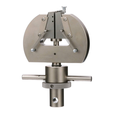
Instron 2716-016 Manual

M10-82716-14
Issue A March 1997
Miniature Grips
for
Low-Force Testing
Operator’s Guide

PROPRIETARY RIGHTS NOTICE
This document and the information that it contains are the property of
InstronCorporation. Rights to duplicate or otherwise copy this document
and rights to disclose the document and the information that it
contains to others and the right to use the information contained therein
may be acquired only by written permission signed by a duly authorized
officer of Instron Corporation.
© Copyright 1997 Instron Corporation

Amendment Incorporation Record
Amendment
No. Brief Description of Content ECR No. Person
Incorporating
Amendment
1
2
3
4
5
6
7
8
9
10
Preliminary Pages
iii

Amendment Incorporation Record
Amendment
No. Brief Description Of Content ECR No. Person
Incorporating
Amendment
11
12
13
14
15
Revision Record
Revision ECR No.
Preliminary Pages M10-82716-14
iv

General Safety Precautions
Materials testing systems are potentially hazardous.
Materials testing involves inherent hazards from high
forces, rapid motions and stored energy. You must be
aware of all moving and operating components which are
potentially hazardous, particularly the actuator in a servo-
hydraulic testing system or the moving crosshead in an
electromechanical testing system.
Whenever you consider that safety is compromised, press
the Emergency Stop button to stop the test and isolate the
testing system from hydraulic or electrical power.
Carefully read all relevant manuals and observe all Warn-
ings and Cautions. The word Warning is used where a haz-
ard may lead to injury or death. The word Caution is used
where a hazard may lead to damage to equipment or to
loss of data.
Ensure that the test set-up and the actual test you will be
using on materials, assemblies or structures constitutes no
hazard to yourself or others. Make full use of all mechani-
cal and electronic limits features. These are supplied for
your safety to enable you to prevent movement of the ac-
tuator piston or the moving crosshead beyond desired re-
gions of operation.
The following pages detail various general warnings that
you must heed at all times while using materials testing
equipment. You will find more specific Warnings and Cau-
tions in the text whenever a potential hazard exists.
Your best safety precautions are to gain a thorough under-
standing of the equipment by reading your instruction
manuals and to always use good judgment.
Preliminary Pages
v

Warning
Disconnect the electrical power supply
beforeremovingthecoverstoelectrical
equipment.
Disconnect equipment from the electrical power supply
before removing any electrical safety covers or replacing
fuses. Do not reconnect the power source while the covers
are removed. Refit covers as soon as possible.
Disconnect power supplies before
removingthecoverstorotatingmachinery.
Disconnect equipment from all power supplies before re-
moving any cover which gives access to rotating machin-
ery. Do not reconnect any power supply while the covers
are removed unless you are specifically instructed to do so
in the manual. If the equipment needs to be operated to
perform maintenance tasks with the covers removed, en-
sure that all loose clothing, long hair, etc. is tied back. Re-
fit covers as soon as possible.
Shut down the hydraulic power supply and
discharge hydraulic pressure before
disconnection of any hydraulic fluid
coupling.
Do not disconnect any hydraulic coupling without first
shutting down the hydraulic power supply and discharging
stored pressure to zero. Tie down or otherwise secure all
pressurized hoses to prevent movement during system op-
eration and to prevent the hose from whipping about in
the event of a rupture.
Preliminary Pages M10-82716-14
vi

Warning
Shut off the supply of compressed gas and
discharge residual gas pressure before you
disconnect any compressed gas coupling.
Do not release gas connections without first disconnecting
the gas supply and discharging any residual pressure to
zero.
Use protective shields or screens if any
possibility exists of a hazard from the failure
of a specimen, assembly or structure under
test.
Use protective shields whenever a risk of injury to operators
and observers exists from the failure of a test specimen, as-
sembly or structure, particularly where explosive disintegra-
tion may occur. Due to the wide range of specimen
materials, assemblies or structures that may be tested, any
hazard resulting from the failure of a test specimen, assem-
bly or structure is entirely the responsibility of the owner and
theuseroftheequipment.
Protect electrical cables from damage and
inadvertent disconnection.
The loss of controlling and feedback signals that can re-
sult from a disconnected or damaged cable causes an open
loop condition which may drive the actuator or crosshead
rapidly to its extremes of motion. Protect all electrical ca-
bles, particularly transducer cables, from damage. Never
route cables across the floor without protection, nor sus-
pend cables overhead under excessive strain. Use padding
to avoid chafing where cables are routed around corners
or through wall openings.
Preliminary Pages
vii

Warning
Wear protective clothing when handling
equipment at extremes of temperature.
Materials testing is often carried out at non-ambient tem-
peratures using ovens, furnaces or cryogenic chambers.
Extreme temperature means an operating temperature ex-
ceeding 60 °C (140 °F) or below 0 °C (32 °F). You must
use protective clothing, such as gloves, when handling
equipment at these temperatures. Display a warning notice
concerning low or high temperature operation whenever
temperature control equipment is in use. You should note
that the hazard from extreme temperature can extend be-
yond the immediate area of the test.
Take care when installing or removing a
specimen, assembly or structure.
Installation or removal of a specimen, assembly or struc-
ture involves working inside the hazard area between the
grips or fixtures. Keep clear of the jaws of a grip or fixture
at all times. Keep clear of the hazard area between the
grips or fixtures during actuator or crosshead movement.
Ensure that all actuator or crosshead movements neces-
sary for installation or removal are slow and, where possi-
ble, at a low force setting.
Preliminary Pages M10-82716-14
viii

Warning
Do not place a testing system off-line from
computer control without first ensuring that
no actuator or crosshead movement will
occur upon transfer to manual control.
The actuator or crosshead will immediately respond to
manual control settings when the system is placed off-line
from computer control. Before transferring to manual con-
trol, make sure that the control settings are such that unex-
pected actuator or crosshead movement cannot occur.
Keep clear of the operating envelope of a
robotic device unless the device is
de-activated.
The robot in an automated testing system presents a haz-
ard because its movements are hard to predict. The robot
can go instantly from a waiting state to high speed opera-
tion in several axes of motion. During system operation,
keep away from the operating envelope of the robot. Deac-
tivate the robot before entering the envelope for any pur-
pose, such as reloading the specimen magazine.
Preliminary Pages
ix

Table of Contents
Chapter Page
1Introduction
Overview 1-1
Purpose 1-2
About this Manual 1-3
Wedge Grips 1-5
Screw Grips 1-7
Chuck Grips 1-9
Lever-Action Fiber Grips 1-11
2 Specifications
Overview 2-1
Wedge Grips 2-2
Specifications 2-2
Dimensions 2-2
Screw Grips 2-4
Specifications 2-4
Dimensions 2-4
Chuck Grips 2-6
Specifications 2-6
Dimensions 2-6
Lever-Action Fiber Grips 2-8
Preliminary Pages M10-82716-14
x

Table of Contents (continued)
Chapter Page
2 Specifications (continued)
Specifications 2-8
Dimensions 2-8
3 Installation
Overview 3-1
General 3-2
Grip Installation 3-3
Fiber Grips 3-4
Converting from Vertical to Horizontal
Mounting 3-4
4Operation
Overview 4-1
General 4-2
Wedge Grips 4-3
Installing Grip Faces 4-3
Loading Specimens 4-4
Screw Grips 4-7
Installing Grip Faces 4-7
Loading Specimens 4-9
Chuck Grips 4-11
Preliminary Pages
xi

Table of Contents (continued)
Chapter Page
4Operation(continued)
Lever Action Fiber Grips 4-13
Loading Specimens 4-13
Adjusting Gripping Force 4-13
5 Maintenance
Overview 5-1
General 5-2
Lubricating Wedge Grips 5-3
6 Illustrated Parts
Overview 6-1
General 6-2
Wedge Grips Parts List 6-4
Screw Grips Parts List 6-6
Chuck Grips Parts List 6-8
Lever Action Fiber Grips Parts List 6-10
Preliminary Pages M10-82716-14
xii

List of Illustrations
Figure Page
1-1. Wedge Grips 1-4
1-2. Screw Grips 1-6
1-3. Chuck Grips 1-8
1-4. Lever-Action Fiber Grips 1-10
2-1. Wedge Grip Dimensions 2-3
2-2. Screw Grips Dimensions 2-5
2-3. Chuck Grips Dimensions 2-7
2-4. Lever-Action Fiber Grips Dimensions 2-9
3-1. Vertical to Horizontal Mounting Conversion 3-6
3-2. Mounting the Grip 3-7
3-3. Adjusting Grip Position on the Post 3-7
4-1. Wedge Grip Operation 4-5
4-2. Screw Grip Operation 4-8
4-3. Lever Action Fiber Grips Operation 4-14
6-1. Wedge Grips Parts Breakdown 6-4
6-2. Screw Grips Parts Breakdown 6-6
6-3. Chuck Grips Parts Breakdown 6-8
Preliminary Pages
xiii

List of Illustrations (continued)
Figure Page
6-4. Lever Action Fiber Grips Parts Breakdown 6-10
6-5. Horizontal Mounting Parts 6-12
Preliminary Pages M10-82716-14
xiv

List of Tables
6-1. Wedge Grips Parts List 6-5
6-2. Screw Grips Parts List 6-7
6-3. Chuck Grips Parts List 6-9
6-4. Lever Action Fiber Grips Parts List 6-11
Preliminary Pages
xv

Preliminary Pages M10-82716-14
xvi

Chapter 1
Introduction
Overview
•Purpose.....................................................Page 1-2
•About this Manual....................................Page 1-3
•Wedge Grips.............................................Page 1-5
•Screw Grips..............................................Page 1-7
•Chuck Grips .............................................Page 1-9
•Lever-Action Fiber Grips.........................Page 1-11
This chapter describes several types of miniature grips
designed for lightly loaded materials testing. Included is
a description of the grips, their specifications, installa-
tion, operation, maintenance, and, in most cases, a parts
breakdown.
Introduction
1-1

Purpose
The four types of miniature grips covered by this manual
are designed for use with Instron’s single column load
frames. Their small size and low force ratings make
them ideal for this application, but they are equally use-
ful on Instron’s regular line of tensile testing instruments.
This manual covers four types of grips: a set of mechani-
cal action wedge grips, manually operated screw grips, a
set of chuck grips similar to the chuck on an electric
drill, and a set of pincer-action fiber grips.
To complete the collection of miniature grips, in addition
to the grips covered here, certain models of pneumatic
wedge grips, cord and yarn grips, and fiber grips from
the standard series of grips of these types can also be
used on the single-screw load frame. Since manuals al-
ready exist for these grips, they are covered there instead
of in this manual.
Purpose M10-82716-14
1-2

About this Manual
The four types of grips described are covered throughout
this manual. The manual is divided into chapters cover-
ing description, specifications, installation, operation,
maintenance, and parts breakdown. The chapters are sub-
divided into information about each type of grip.
Throughout the chapters, the order of presenting the
grips –wedge, screw, chuck, and fiber –the same, so
that you will find navigating through the manual easier,
and can easily find the information about the particular
grip you are working with. Each type of grip has its own
major heading within each chapter.
Introduction
About this Manual
1-3

Figure 1-1. Wedge Grips
About this Manual M10-82716-14
1-4
This manual suits for next models
1
Table of contents
Other Instron Industrial Equipment manuals


