Seikosha GP-550A User manual

WARNING:
“This
eguipment
has
been
certified
to
comply
with
the
limits
for
a
Class
B
computing
device,
pursuant
to
Subpart
J
of
Part
15
of
FCC
Rules.
Only
computers
certified
to
comply
with
the
Class
B
limits
may
be
attached
to
this
printer.
Operation
with
noncertified
computers
is
likely
to
result
in
interference
to
radio
and
TV
reception."
*This
equipment
generates
and
uses
radio
frequency
and
if
not
installed
and
used
properly,
that
is,
in
strict
accordance
with
the
manufacturer's
instructions,
may
cause
interference
to
radio
and
television
reception.
It
has
been
tested
and
found
to
comply
with
the
limits
for
a
Class
B
comput-
ing
device
in
accordance
with
the
specifications
in
Subpart
J
of
Part
15
of
FCC
Rules,
which
are
designed
to
provide
reasonable
protection
against
such
interference
in
a
residential
installation.
However,
there
is
no
guarantee
that
interference
will
not
occur
in
a
particular
installation.
If
this
equipment
does
cause
interference
to
radio
or
television
reception,
which
can
be
determined
by
turning
the
equipment
off
and
on,
the
user
is
encouraged
to
try
to
correct
the
interference
by
one
or
more
of
the
following
measures:
*
Reorient
the
receiving
antenna
*
Relocate
the
computer
with
respect
to
the
receiver
е
Move
the
computer
away
from
the
receiver
е
Plug
the
computer
into
a
different
outlet
so
that
computer
and
receiver
are
on
different
branch
circuits.
If
necessary,
the
user
should
consult
the
dealer
or
an
experienced
radio/
television
technician
for
additional
suggestions.
The
user
may
find
the
following
booklet
prepared
by
the
Federal
Communications
Commission
helpful:
*How
to
Identify
and
Resolve
Radio-TV
Interference
Problems."
This
booklet
is
available
from
the
U.S.
Government
Printing
Office,
Washington,
D.C.
20402,
Stock
No.
004-000-00345-4.
INTRODUCTION
Congratulations
on
your
purchase
of
the
SEIKOSHA
GP-550A
GRAPHIC
PRINTER.
This
Printer
is
a
high-density
dot-matrix
printer
with
a
unique
two-hammer
system
which
can
perform
a
variety
of
different
printing
operations.
Be
sure
to
read
this
Owner's
Man-
ual
carefully
in
order
to
use
the
Printer
to
its
fullest.
Main
Features
*
Various
character
fonts
—
Standard,
Condensed,
Correspondence,
Italic
Cursive,
Super-
script/
Subscript,
and
Proportional
characters.
Graphics
—
standard
and
high-resolution.
Underline
capability.
Minimum
linefeed
is
1/120
inch.
Tractor
feed
and
friction
feed
are
standard.
The
ink
ribbon
cassette
has
an
inker
that
can
be
replaced
as
the
ink
is
used
up.
Automatic
printing
takes
place
when
the
buffer
becomes
full.
Self
test
printing
is
standard
to
provide
self
diagnosis.

CONTENTS
[1]
[2]
[3]
[4]
[5]
[6]
[7]
[8]
GENERAL
SPECIFICATIONS
1
UE
e
a
gh
Ke
eee
yor
1
2,
Paper
feed
specihicati
eissaia
id
Ын,
аланнан
жанча
н
2
Spa
ОВ
ЗАО
CAEL
CONUS
епархии
дандар
кімді»
3
4.
ПИК
прроп
specificatiOliB......-..—.«««
oc
adayi
Беван
3
5.
Орөгайно
Sn
vironment
’scscasscascececcocncvearstesdsecsansstasansapssapssvansngncnnseseuaincae
3
DESCRIPTION
OF
THE
ОР-55ОА
................................................................
4
QR
07
0
gp
oom
rr
5
2.
ВИА
T
E
o
MR
lee
е
но
b
З/
ЕНБ
Switch.
ИЕН
a
e
5
BOR
EE
SWIÉOD.
реечные
N
a
R
5
5.
POWER
lamp
(red)
......
A
15
an
|
gg
С
PRANK
А
5
BADEN
a
kğ
laa
near
REEL
REESE
ER
6
ye
|
ЙТ...
EO
TTC
TREES
6
2:
900155656616
of
DODOF
oorr
rrt
eerog
orae
toos
nort
gil
seno
pasa)
Yoann
qur
8
RIBBON
INSTALLATION/REMOVAL
...............
eren
9
о
ЕО
IDEM
m
9
PB
co
Gn
Tene
İİ
ETIN
SES
10
HEAD'POSHION
ADJUSTMENT.
..............................ььдииидиалдддаивинкинидявани»»
11
INTERFAGING
..........................
12
1.
Connector
on
the
cable
side
12
2.
Connector
on
the
printer
sideanditspinoutchart..........................
12
3.
Explanation
of
the
input/output
signals.............................................
13
4.
Electrical
conditions
14
5.
Timing
chart
15
CONTROL
СОО
АМАН
5...2...
cane
MEM
basan
16
GONTROL
GODER
.
18
1.
Print
commands
18
2.
Elongation
18
3.
Print
position
specification
19
4.
Character
set
specification
.
за
5.
Character
repetition
..................
eerte
nennen
tenente
tnter
21
6.
Graphic
mode
22

7.
Graphic
repelition
ossis
dike
ом
23
8:
mese
si
басни;
„аннады
оаза
ох
24
9.
Page
length:
SpecifiGatiOH
5...
cccscececceccacssascessasssssessuncsocuacsccaverssbivessvescoveses
24
10508060
НӨ:
РИА
С
ME
arta)
EYE)
AM
ise
А
дээ
25
TI
(e
2
MEN
Rp
eee
eze
eer
vd
oe
Ne
A
Lo
AR
12.
Bold
funcion
25
[9]
ERROR
CONDITIONS
26
[10]
SELF
TEST
PRINTING
26
[11]
AUTOMATIC
PRINTING
FUNCTION
26
[12]
DIP
SWITCH
SETTINGS
27
ГІЗІССОПРЕСТАВЫЕ,,/
азасы
sra
арын»
28
АТ
PRINT
EXAMPLES
RENNES
ee
el
ка
ананыц
29
1.
СПагастег
Вебе...
г...
n
o
ereesensronaskeskésPa
eba
saya
MA
ca
E
ан
29
PA
A
e
eT
о
ЕАН
PEREAT
ТТТ
29
SOPEBPBDOSIOR
ur
ge
Re
И
29
ELIE
|
a
MM
eee
РИ
И
30
e
e
NUN
анги
p
otn
e
emily
30
af
DENER
MM
A
MM
Ya
Ея
31
7.
16-bit
graphics...
31
8.
Line
feed
spacing
..
2032
С
UY
е
ITO
33
A,
АИ
еее
УИ
33
[15]
TROUBLESHOOTING
...........
а
|
[16]
CARING
FOR
YOUR
PRINTER
..................................................................
35

[1]
GENERAL
SPECIFICATIONS
1.
Printing
specifications
Qo
оо»
СНАВ
СНАВ
NO.
OF
CHAR.
SETS
HxV
DOTS
|
SPACEDOTS
7
мен
/
име|
PRINT
SPEED!
CHARS
—
—
=к——=_=————==———=———=
Standard
Pica
9x8
3
10
80
50cps
139
a
a
ж-ға
та
андах
re
Elongate
Ка
18x8
6
5
40
25
139
Standard
Elite
9х8
1
12
96
60
139
oa
18x8
2
6
48
30
139
Condensed
5x8
2
17
136
86
139
ы
10х8
4
85
68
43
139
ке
машы
Цай
ei
НЕВЕ
шог
ла
olmama
feng
рева
ente
с
екеніне
9х16
3
10
80
139
k
—
т
ri
seri
18x16
6
5
40
12
189
Seen
9x16
1
12
96 30
139
ellere
18x16
2
6
48
15
139
Найс
Cursive
12х16
0
10
80
25
139
и
4
Italic
Cursive
я
24х16
0
5
40
12
139
(RT
Super
Script
5x8
2
17
136
43,
139
борог
5с!
10х8
4
85
68
21
139
—
Sub
Script
5x8
2
17
136
43
139
ч
——
———
|
——
MOM
10x8
4
85
68
21
189
Proportional
nx16
=
= = -
139
—
Proportional
2nx16
= a
5
es
139
(1)
Printing
method
(2)
Character
sets
Impact
type
dot
matrix
(SEIKOSHA's
unique
2-hammer
method)
Elongated
(3)
Graphics
Arbitrary
combinations
of
8
vertical
dots
Arbitrary
combinations
of
16
vertical
dots
(4)
Dot
density
Horizontal
1/120"
(0.21mm)
Vertical
1/120"
(0.21mm)
(5)
Printing
direction
Unidirectional
(left
to
right)
a.
1-pass
printing:
Standard,
Standard
elite,
Condensed
and
8-dot
graphics
b.
2-pass
printing:
Correspondence,
Correspondence
elite,
Italic
cursive,
Super/subscript,
Propor-
tional
and
16-dot
graphics
(6)
Line
spacing
1/6",
1/8",
2/15",
1/12"
and
N/120"
(М-0--99)
(7)
Multiple
copies
Original
plus
опе
copy
(45Kg
+
35Kg
paper
)
(8)
Intermixing
printing
Intermixing
text
and
graphics
on
the
same
line
is
allowed
2.
Paper
feed
specifications
(1)
Paper
feed
direction
Forward
direction
only
(2)
Paper
feed
method
Pin
feed......
maximum
10
inch
width
paper
Friction
feed
(3)
Minimum
line
feed
amount
1/120"
(4)
Line
feed
speed
10
lines/sec
(1/6"
line
feed
pitch)

.
Paper
specifications
(1)
Paper
width
4.5
—
10
inches
for
pin
feed
paper
Tractor
width
is
adjustable.
(2)
Paper
thickness
and
weight
recommended
0.07mm
(2.8
mils)
45~55Kg
in
Japan
or
15—18
pounds
in
USA
(3)
Paper
Type
Continuous
form
paper
Single.sheet
paper
.
Ink
ribbon
specifications
Special
single
color
cassette
type.
.
Operating
environment
(1)
Power
supply
120,
220/240
МАС
+
10%,
50/60Hz
(2)
Power
consumption
30
watts
(printing
characters)
11
watts
(stand
by)
(3)
Temperature
5°C~40°C
(4)
Humidity
20%
~
80%
(no
condensation)
(5)
External
dimensions
420W
x
113H
x
305Dmm
(6)
Weight
5.5Kg
[2]
DESCRIPTION
OF
THE
GP-550A
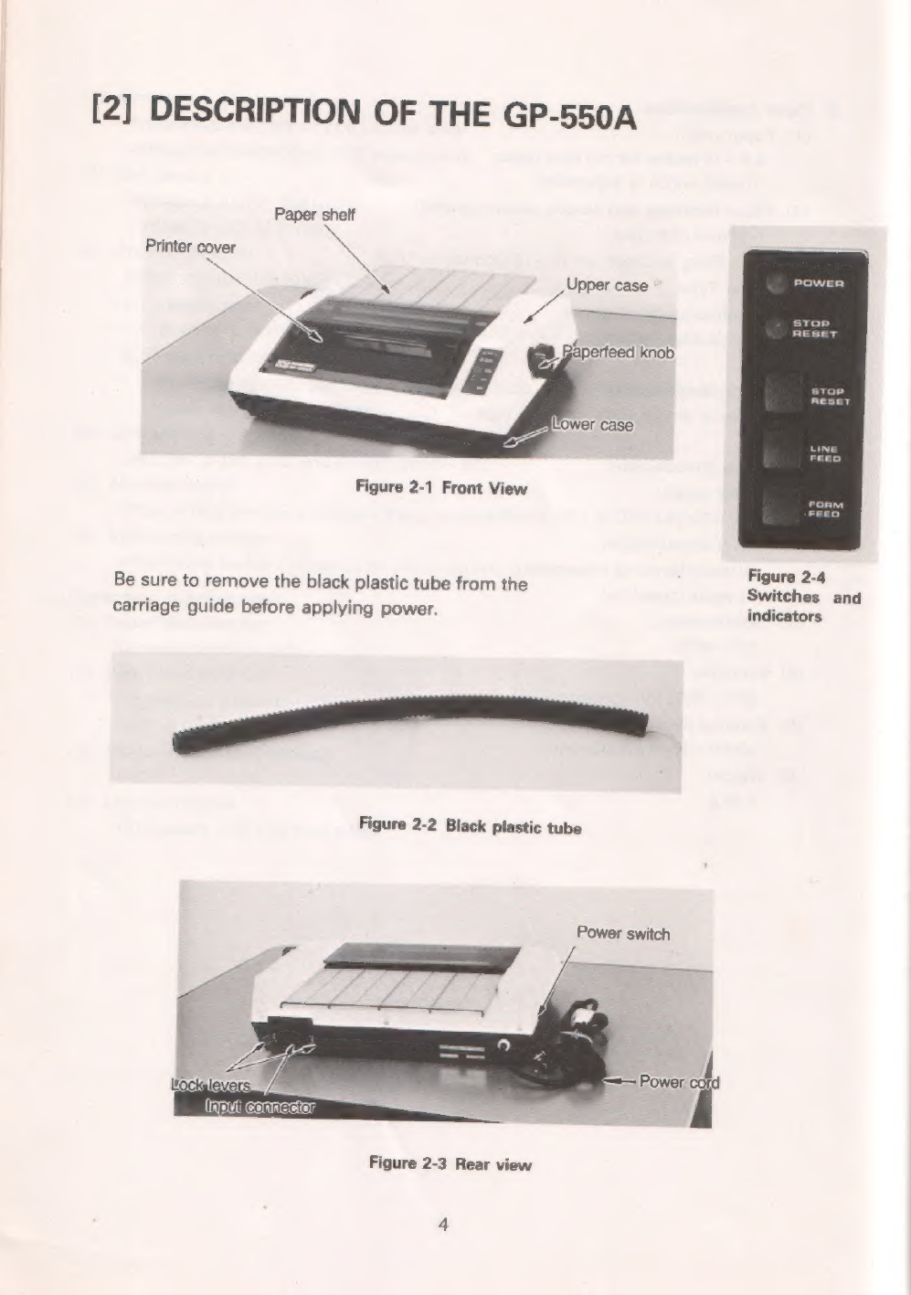
Paper
shelf
Printer
cover
x
i»
Figure
2-1
Front
View
i
Figure
2-4
Be
sure
to
remove
the
black
plastic
tube
from
the
ae
d
carriage
guide
before
applying
power.
indicators
Figure
2-2
Black
plastic
tube
Power
switch
Figure
2-3
Rear
view
.
Power
switch
The
power
switch
is
located
on
the
left
of
the
printer.
.
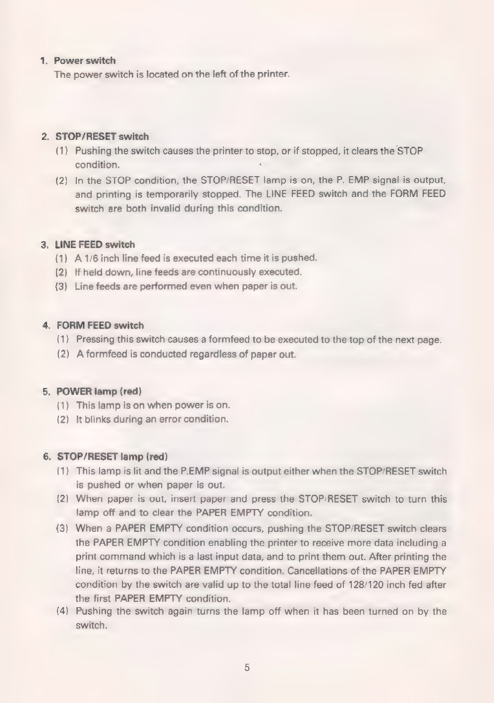
STOP/RESET
switch
(1)
Pushing
the
switch
causes
the
printer
to
stop,
or
if
stopped,
it
clears
the
STOP
condition.
.
(2)
In
the
STOP
condition,
the
STOP/RESET
lamp
is
on,
the
P.
EMP
signal
is
output,
and
printing
is
temporarily
stopped.
The
LINE
FEED
switch
and
the
FORM
FEED
Switch
are
both
invalid
during
this
condition.
.
LINE
FEED
switch
(1)
A
1/6
inch
line
feed
is
executed
each
time
it
is
pushed.
(2)
If
held
down,
line
feeds
are
continuously
executed.
(3)
Line
feeds
are
performed
even
when
paper
is
out.
FORM
FEED
switch
(1)
Pressing
this
switch
causes
a
formfeed
to
be
executed
to
the
top
of
the
next
page.
(2)
A
formfeed
is
conducted
regardless
of
paper
out.
.
POWER
lamp
(red)
(1)
This
lamp
is
on
when
power
is
on.
(2)
It
blinks
during
an
error
condition.
.
STOP/RESET
lamp
(red)
(1)
This
lamp
is
lit
and
the
P.EMP
signal
is
output
either
when
the
STOP/RESET
switch
is
pushed
or
when
paper
is
out.
(2)
When
paper
is
out,
insert
paper
and
press
the
STOP/RESET
switch
to
turn
this
lamp
off
and
to
clear
the
PAPER
EMPTY
condition.
When
a
PAPER
EMPTY
condition
occurs,
pushing
the
STOP/RESET
switch
clears
the
PAPER
EMPTY
condition
enabling
the
printer
to
receive
more
data
including
a
print
command
which
is
a
last
input
data,
and
to
print
them
out.
After
printing
the
line,
it
returns
to
the
PAPER
EMPTY
condition.
Cancellations
of
the
PAPER
EMPTY
condition
by
the
switch
are
valid
up
to
the
total
line
feed
of
128/120
inch
fed
after
the
first
PAPER
EMPTY
condition.
Pushing
the
switch
again
turns
the
lamp
off
when
it
has
been
turned
on
by
the
Switch.
(3
(4

[3]
PAPER
LOADING
1.
Continuous
forms
(1)
Grasp
the
back
of
the
printer
cover
and
remove
it
by
lifting
upwards.
paper
shelf
(2)
Turn
the
paper
shelf
upright
and
pull
it
up
to
remove
it.
Move
the
head
adjustment
lever
all
the
way
toward
the
front
of
the
printer.
Refer
to
"
HEAD
POSITION
ADJUST-
MENT"
Figure
3-2
(3)
Use
both
hands
to
insert
the
paper
from
the
rear
and
then
use
the
right
hand
to
turn
the
paperfeed
knob
in
a
clockwise
direction
until
it
appears
bet-
ween
the
platen
and
the
print
head.
Figure
3-3
Note:
If
the
paper
does
not
appear
by
turning
only
the
knob,
use
your
hand
to
push
the
paper
into
the
printer
while
turning
the
knob.

(4)
Lift
up
the
friction
roller
bar
and
open
the
tractor
covers
to
the
side.
Figure
3-4
(5)
With
the
holes
along
both
sides
of
the
paper
matched
up
with
the
paper
feed
pins
on
the
left
and
right
tractors,
close
the
tractor
covers.
Lower
the
friction
roller
bar,
positioning
the
friction
rollers
on
the
bar
so
that
they
rest
directly
on
top
of
the
two
large
rubber
tractor
rings.
Use
the
LINE
FEED
switch
to
perform
line
feeds
in
order
to
tighten
the
paper.
If
the
tactor
spacing
does
not
match
the
paper
width,
slide
the
tactors
to
the
left
or
right
as
needed.
Make
sure
that
the
paper
is
positioned
so
that
the
first
and
last
print
positions
are
on
the
paper.
Figure
3-5
(6)
Return
the
head
adjustment
lever
to
its
original
position.
Replace
the
paper
shelf
and
printer
cover
in
that
order.
Adjust
the
print
position
by
pushing
the
LINE
FEED
switch.
7

Figure
3-6
Note:
After
manually
advancing
paper
by
the
paper
feed
knob,
it
is
recommended
that
the
LINE
FEED
switch
be
pushed
at
least
once
in
order
to
avoid
having
abnormal
double
pass
printing
for
the
first
line.
2.
Single
sheets
of
paper
Except
for
those
involving
the
tractors,
all
of
the
operations
are
the
same
and
follow
the
order
of
section
[3]-1.
Note:
1.
For
proper
friction
feeding,
be
sure
that
the
friction
rollers
are
positioned
directly
on
top
of
the
rubber
tractor
rings
and
that
these
two
sets
of
rollers
properly
grasp
the
paper.
2.
The
paper
empty
switch
is
located
at
a
position
about
11/2”
away
from
the
metal
side
plate
on
the
left.
The
left
edge
of
the
single
sheet
of
paper
must
cover
the
switch
in
order
to
avoid
the
PAPER
EMPTY
condition.
Figure
3-7
8
[4]
RIBBON
INSTALLATION/REMOVAL
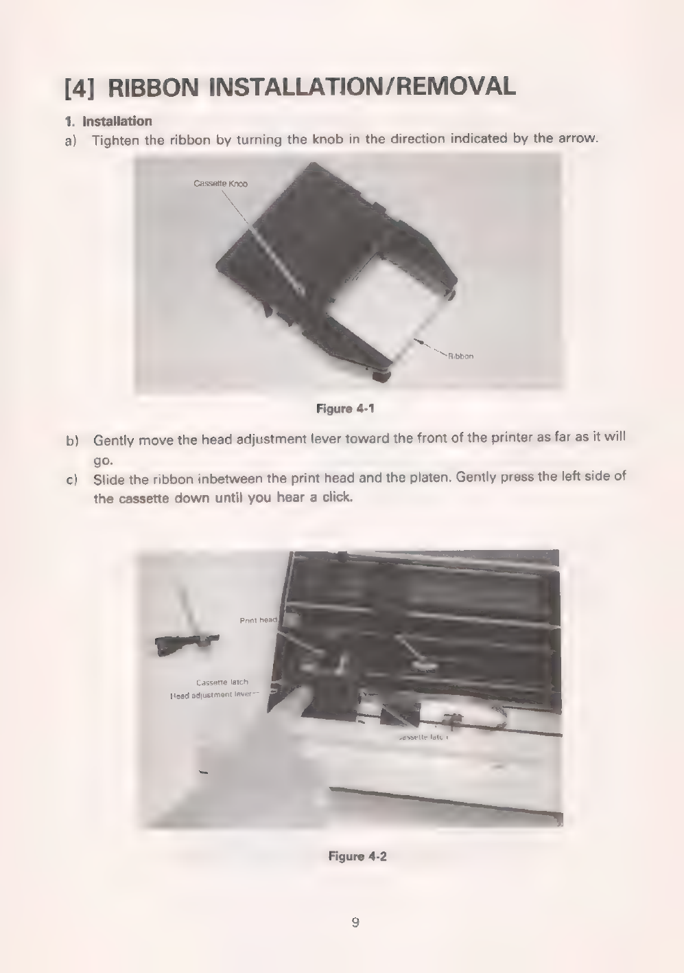
1.
Installation
a)
Tighten
the
ribbon
by
turning
the
knob
in
the
direction
indicated
by
the
arrow.
Саззейе
Knob
Ribbon
Figure
4-1
b)
Gently
move
the
head
adjustment
lever
toward
the
front
of
the
printer
as
far
as
it
will
go.
c)
Slide
the
ribbon
inbetween
the
print
head
and
the
platen.
Gently
press
the
left
side
of
the
cassette
down
until
you
hear
a
click.
Print
head]
Cassette
latch.
Head
adjustment
lever
—
Figure
4-2

d)
Then,
while
rotating
the
cassette
knob
in
the
direction
indicated
by
the
arrow,
press
the
right
side
of
the
cassette.
Do
not
force
the
cassette
down.
Push
it
in
gradually
while
turning
the
cassette
knob
in
the
indicated
direction.
Once
the
new
cassette
is
installed,
tighten
the
ribbon
by
turning
the
cassette
knob
in
the
indicated
direction.
Figure
4-3
e)
Set
the
head
adjustment
lever
to
its
original
position.
Note:
Do
not
print
without
paper
and/or
ribbon.
The
print
head
or
platen
will
be
damaged.
2.
Removal
a)
Move
the
head
adjustment
lever
toward
the
front
of
the
printer
as
far
as
it
will
go.
b)
Gently
push
the
ribbon
cassette
latch
on
the
right
side
outward
using
your
thumb,
and
remove
the
cassette
by
lifting
it
upwards
using
your
middle
finger.
Figure
4-4
10

[5]
HEAD
POSITION
ADJUSTMENT
The
head
adjustment
lever
is
used
to
adjust
for
varying
thicknesses
of
paper
and
varying
printing
conditions.
The
head
adjustment
lever
is
moved
by
pressing
it
toward
the
outside
as
it
is
moved
back
and
forth.
When
adjusting,
make
sure
that
the
foot
of
the
lever
is
set
in
one
of
the
click
holes.
The
head
is
adjusted
by
moving
the
lever
toward
for
thick
paper
and
toward
©
for
thin
paper.
The
printer
is
shipped
with
the
lever
foot
set
to
position
(3).
The
lever
foot
should
be
set
to
(8)
(©)
for
insertion
and
removal
of
the
ribbon
and
the
paper.
Red
mark
Head
adjustment
lever
Lever
foot
08
(
өв
holes
0090
N
Figure
5-1
Internal
left
side
view
[6]
INTERFACING
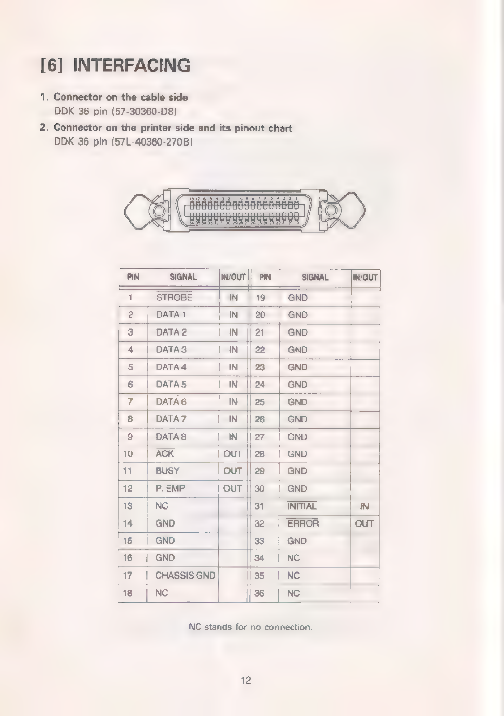
1.
Connector
on
the
cable
side
DDK
36
pin
(57-30360-D8)
2.
Connector
on
the
printer
side
and
its
pinout
chart
DDK
36
pin
(57L-40360-270B)
2
3
|
DATA2
IN
||21
|
GND
4
|
DATAS
IN
||22
|
GND
5
|
DATA4
ІМ
|23
|
GND
6
|
DATAS
IN
||24
|
GND
7
|
DATA6
IN
||25
|
GND
8
|
DATA7
ІМ
||26
|
GND
9
|
ПАТАВ
IN
|27
|
GND
10
|
ACK
OUT
|
28
|
GND
11
|
BUSY
Тол
|29
|
емо
12
|
Р.ЕМР
OUT
|30
|
GND
13
|
NC
31
|
INITIAL
IN
14
GND
32
|
ERROR
OUT
15
|
GND
83
|
GND
16
|
GND
34
|
NC
Цэр
17
|
CHASSIS
GND
35
|
Nc
18
|
Nc
|ж
|
ме
NC
stands
for
no
connection.
12
3.
Explanation
of
the
input/output
signals
a)
Input
signals
to
the
printer
@DATA1~DATA8
These
form
the
8
bit
data
signal.
A
given
line
is
“HIGH”
if
the
data
bit
is
“1”,
®
STROBE
This
signal
is
used
to
strobe
the
8
bits
of
data
into
the
printer.
The
data
is
read
in
when
this
line
goes
“LOW”.
®
INITIAL
This
signal
is
used
to
set
the
printer
to
its
initial
state.
This
pin
is
normally
“HIGH”.
Bringing
it
“LOW”
stops
the
execution
of
the
printer
and
setting
it
back
to
“HIGH”
starts
the
execution
of
the
clearing
sequence
that
sets
it
to
its
initial
con-
dition.
b)
Output
signals
from
the
printer
е
BUSY
This
signal
indicates
that
the
printer
is
BUSY.
When
"HIGH",
new
data
cannot
be
input.
е
АСК
This
signal
is
always
output
at
the
end
of
the
BUSY
signal
and
indicates
that
data
input
has
been
completed.
The
pulse
width
is
about
7.5us.
e
ERROR
This
signal
goes
"LOW"
when
the
Printer
enters
an
error
condition.
e
P.
EMP
(PAPER
EMPTY)
This
signal
goes
"HIGH"
either
when
the
printer
is
out
of
paper
or
when
the
STOP/RESET
switch
is
pushed.
In
thes
case
the
printer
stops
processing
data.
In
order
to
clear
this
condition,
insert
paper
and
push
the
STOP/RESET
switch.
Refer
to
the
"STOP/RESET
lamp"
on
page
5.
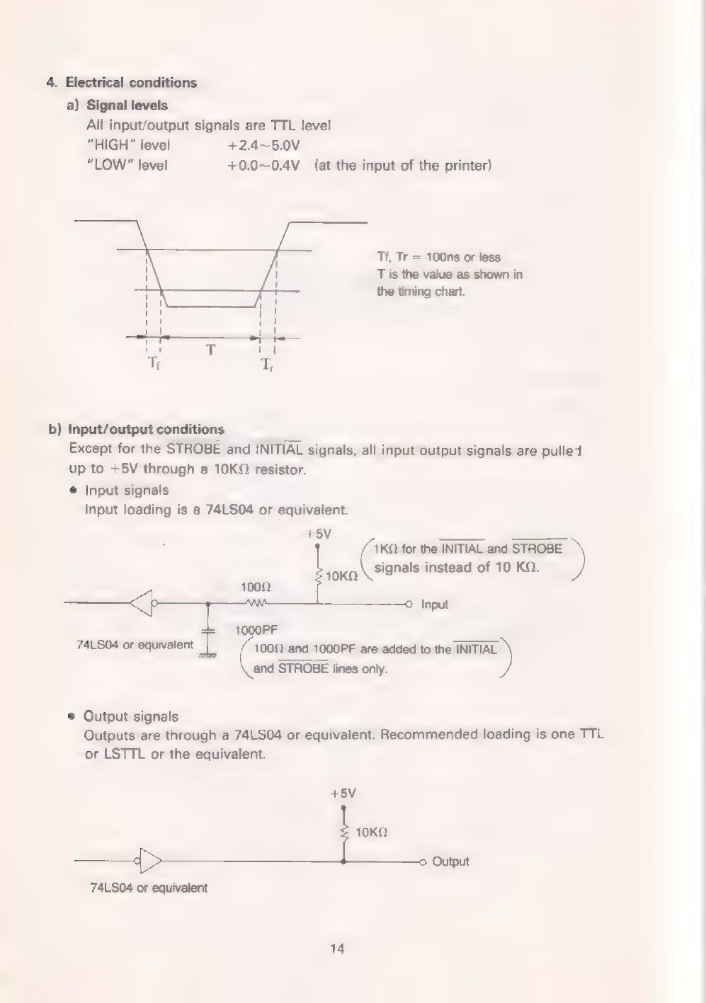
4.
Electrical
conditions
a)
Signal
levels
All
input/output
signals
are
TTL
level
“HIGH”
level
+2.4~5.0V
“LOW”
level
+0.0~0.4V
(at
the
input
of
the
printer)
7
j
Tf,
Tr
=
100ns
or
less
:
1
T
is
the
value
as
shown
in
|
1
the
timing
chart.
"ER:
1
La
ка
|
1
БЭ
T
11
Т;
®
b)
Input/output
conditions
Except
for
the
STROBE
and
INITIAL
signals,
all
input/output
signals
are
pulled
up
to
+5V
through
а
10КО
resistor.
®
Input
signals
Input
loading
is
a
74LS04
or
eguivalent.
+5V
———
=.
for
the
INITIAL
and
STROBE
)
лока
signals
instead
of
10
КО.
Input
1000PF
74LS04
or
eguivalent
ар
1000
and
1000РЕ
are
added
to
the
INITIAL
and
STROBE
lines
only.
*
Output
signals
Outputs
are
through
a
74LS04
or
equivalent.
Recommended
loading
is
one
TTL
or
LSTTL
or
the
equivalent.
45V
токо
Output
74LS04
or
eguivalent
Table of contents
Other Seikosha Printer manuals


