integrum OPRA AXOR II User manual

OPRA™ AXOR™ II
Instructions For Use

INSTRUCTIONS FOR USE
2
TABLE OF CONTENTS
INTENDED USE 3
EXTERNAL PROSTHETIC COMPONENTS 5
ATTENTION 3
APPLICABLE FOR USA 3
PRODUCT DESCRIPTION 4
SPECIFICATION 4
LABELLING 4
INSTALLATION 5
CONNECTING THE PROSTHETIC COMPONENTS TO THE AXOR™ II 5
ATTACHING THE AXOR™ II TO THE ABUTMENT (DONNING) 6
DETACHING THE AXOR™ II FROM THE ABUTMENT (DOFFING) 7
ALIGNING THE AXOR™ II IN THE DIRECTION OF WALKING 7
RELEASE FEATURES 7
RESETTING THE AXOR™ II AFTER RELEASE IN BENDING/FLEXION 8
RESETTING THE AXOR™ II AFTER RELEASE IN ROTATION 8
CLEANING AND HYGIENE INSTRUCTIONS 9
MAINTENANCE 9
PATIENT EDUCATION 10
WARNINGS 10
APPENDIX 1 – LABEL SPECIFICATION 11

3
INSTRUCTIONS FOR USE
INTENDED USE
ATTENTION
The OPRA Axor™ II is a medical device designed to be used as part of the OPRA™ Implant System. The Axor™ II has
two functions:
i) It protects the OPRA™ Implant System from excessive loads via a release mechanism in both bending and rota-
tion. The function of the device is to limit rotational forces along the centre line of the implant and bending forces
when the prosthetic knee is exed to its maximum position.
ii) It provides an interface between the OPRA™ Implant System and commercially available prosthetic components
via the 4-hole conguration which is commonly used for prosthetic components.
The Axor™ II is designed to be used for normal everyday activities.
EXTERNAL PROSTHETIC COMPONENTS
The external prosthetic connection device, Axor™ II, provides a standard connection to other prosthetic components
that would include the prosthetic knee and foot. A standard European 4 hole male/female mounting system is utilized in
the external prosthetic device. This allows the OPRA™ system to be connected to all prosthetic systems that utilize this
standardized connection method. The OPRA™ System is recommended for use with commercially available non-micro-
processor- controlled prosthetic knees and microprocessor controlled prosthetic knees that do not include powered
activation of exion and extension of the prosthetic knee.
Prosthetic components with internal power supply attached to the Axor™ II must comply with the standard IEC60601
for medical electrical equipment.
[ The responsible physician must approve the use of the Axor™ II.
[ The Axor™ II is intended to be used together with the OPRA™ Implant System only and for above-knee ampu-
tees only.
[ The Axor™ II must be installed by a prosthetist certied by Integrum.
[ The Axor™ II is intended for single patient use only.
[ The Axor™ II is intended for patients with body weight equal or less than 100kg/220lb including prosthesis.
APPLICABLE FOR USA
CAUTION: Federal (US) law restricts this device to sale by or on the order of a physician.

INSTRUCTIONS FOR USE
4
PRODUCT DESCRIPTION
LABELLING
SPECIFICATION
The following parts are marked in Figure 1:
1. Jaws for attachment to the Abutment
2. Rotatable grip for attachment/detachment
3. Alignment nuts
4. Plug for adjustment screw access
5. Prosthetic connection area (with the 4-hole conguration)
For label specication, please see Appendix 1.
Figure 1. Product description.
Factory setting of torque release level 15 ± 2 Nm
Factory setting of bend release level 70 ± 5 Nm
Building height (marked in Figure 1) 52 mm
Total height (marked in Figure 1) 76 mm
Weight of the device 0.8 kg

5
INSTRUCTIONS FOR USE
INSTALLATION
When installing the Axor™ II for a new patient, adhere to the following steps (each step is described in separate sec-
tions):
1. Connecting the prosthetic components to the Axor™ II
2. Attaching the Axor™ II to the Abutment (Donning)
3. Detaching the Axor™ II from the Abutment (Dofng)
4. Aligning the Axor™ II in the direction of walking
CONNECTING THE PROSTHETIC COMPONENTS TO THE AXOR™ II
In order to achieve the correct position of the prosthetic knee axis, the distance between the Axor™ II and the pros-
thetic components must be adjusted individually depending on the length of the residual limb. If needed, use one or
several of the OPRA™ Axor™ II Extension Plates (available in 5, 10 and 20 mm heights) to achieve the required height.
Attach the prosthetic components (e.g. pyramid adaptor, prosthetic knee etc.) to the Axor™ II using standard techniques
and in accordance with the manufacturer’s instructions for the prosthetic component(s). Use M6 screws to connect the
prosthetic components to the 4-hole conguration at the bottom of the Axor™ II (no 5 in Figure 1). The length of the
screws depends on the prosthetic components used but it is recommended to use as long screws as possible without
exceeding the 12mm thread depth in the Axor™ II.
The plug in the Axor™ II front plate sits in a hole (no 4 in Figure 1) which allows for access to adjustment screws of the
prosthetic components. Gently remove the plug from the back using a tool (e.g. screw driver).
CAUTION! The front plate marked with Integrum must point forward in the direction of walking to function as intended.
CAUTION! Check that the Axor™ II does not interfere with the prosthetic components (e.g. the prosthetic knee) in
either maximum exion or in the fully extended position.

INSTRUCTIONS FOR USE
6
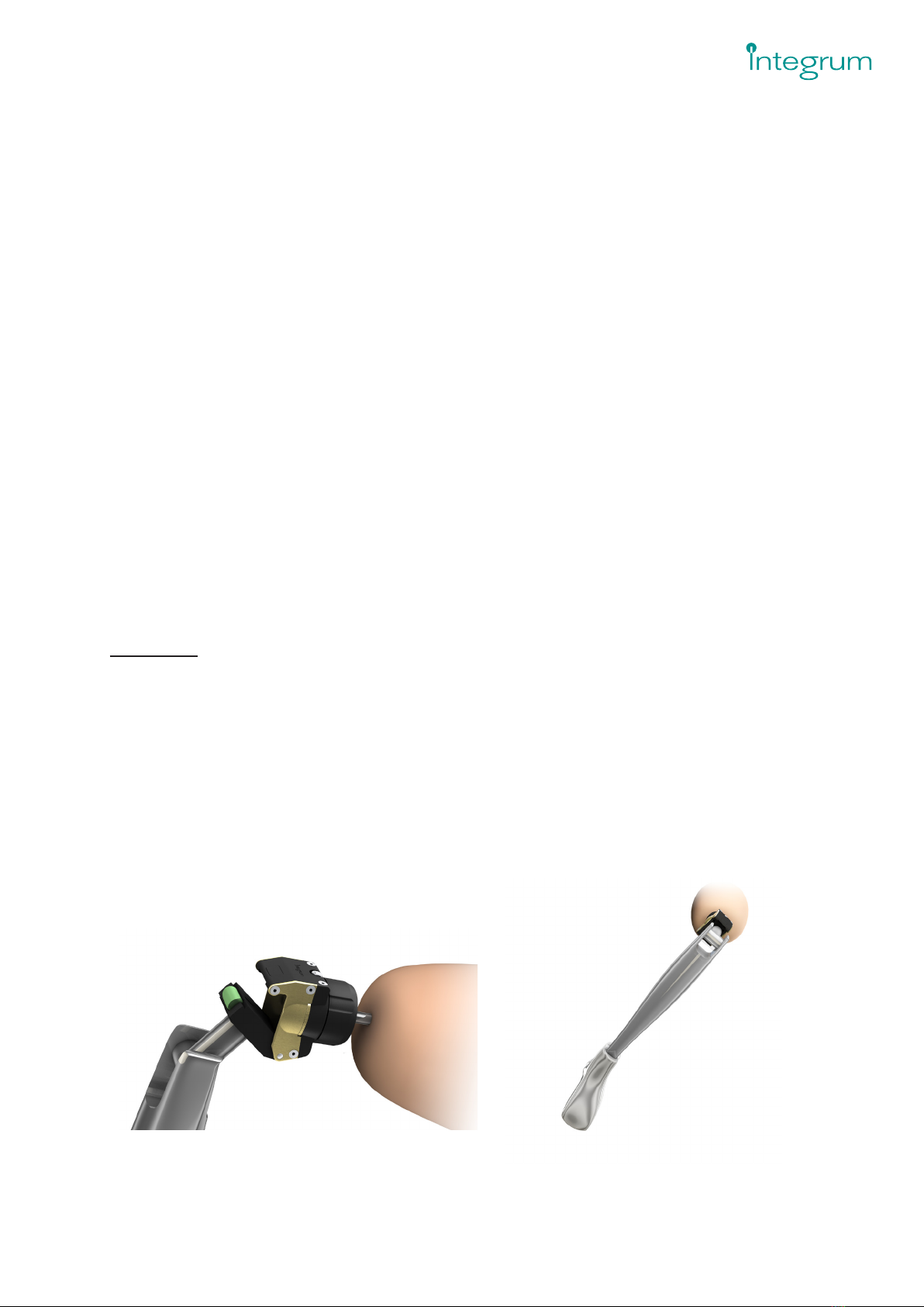
Figure 2. Turn the grip counter-clockwise until it stops.
ATTACHING THE AXOR™ II TO THE ABUTMENT (DONNING)
The top part of the Axor™ II has four conical jaws with a square opening for the Abutment (no 1 in Figure 1). The jaws
are tightened with a screw mechanism that is managed by hand (grip shown as no 2 in Figure 1).
The patient should be instructed to attach the Axor™ II to the Abutment through the following procedure:
1. Sit down while attaching the Axor™ II.
2. Open the jaws by turning the grip counter-clockwise by hand until it stops and the Abutment can enter the
Axor™ II (see Figure 2).
3. Insert the Abutment while keeping the Axor™ II open. Make sure that the Abutment contacts the bottom of the
jaws (see Figure 3).
4. Release the grip and let it rotate freely. Tighten the grip clockwise by hand.
5. Move the leg side to side and tighten the grip further by hand to make sure it is rmly attached to the Abutment.
6. Try to pull off the Axor™ II to conrm that it is properly attached.
CAUTION! You should not use the Axor™ II if a stable attachment cannot be achieved. Contact your prosthetist if there
is any problem with the attachment.
CAUTION! Incorrect attachment (see Figure 4) may cause the Axor™ II to fall off the Abutment.
Figure 3. Fully inserted Abutment. Figure 4. Incorrect attachment to the Abutment.
7
INSTRUCTIONS FOR USE
DETACHING THE AXOR ™ II FROM THE ABUTMENT (DOFFING)
The patient should be instructed to remove the Axor™ II from the Abutment through the following procedure:
1. Sit down to remove the Axor™ II.
2. Open the jaws by turning the grip counter-clockwise by hand.
3. It may take a higher initial amount of force to get the Axor™ II to release from the Abutment and in some
instances an audible popping noise can be heard when the Axor™ II starts to release from the Abutment and the
jaws begin to open.
4. Open the jaws wide enough so the Axor™ II can easily be removed from the Abutment.
5. Pull the Axor™ II off the Abutment.
ALIGNING THE AXOR™ II IN THE DIRECTION OF WALKING
The Axor™ II is aligned in the direction of walking according to the following steps:
1. Untighten the two alignment nuts (no 3 in Figure 1) maximum half a turn.
CAUTION! Untightening the alignment nuts more than half a turn may damage the Axor™ II.
2. Rotate the Axor™ II until it is aligned in the direction of walking.
3. Tighten the two alignment nuts with a torque of 5 Nm to lock the position of the prosthesis.
RELEASE FEATURES
The Axor™ II releases when subjected to high bending and/or rotational moments in order to protect the OPRA™
Implant System from excessive loads.
The Axor™ II releases according to the gures below:
[ In the bending/exion direction the Axor™ II is opened according to Figure 5.
[ In the rotational direction the Axor™ II rotates around its axis in both clockwise and counter-clockwise directions
according to Figure 6.
The two release mechanisms can be reset without using any tools.
Figure 5. Bend release. Figure 6. Rotation release.
INSTRUCTIONS FOR USE
8
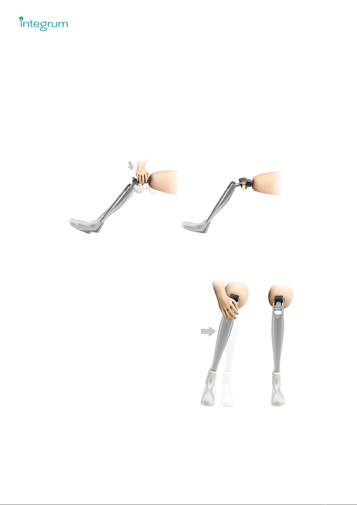
RESETTING THE AXOR™ II AFTER RELEASE IN BENDING/FLEXION
When the Axor™ II has released in bending/exion direction it can be reset:
1. Sit on a chair or on the oor with the leg straight out and the heel of the prosthetic foot on a solid support. If
needed, remove the prosthesis from the Abutment before resetting the Axor™ II.
2. Gently close the Axor™ II until the green release plunger makes contact with the edge of the housing.
3. Press down on the Axor™ II according to Figure 7 until it clicks back into the correct position. A moderate to high
force may be required.
CAUTION! Avoid resetting the Axor™ II if there is any pain during the reset procedure. In case of pain, please contact
your physician immediately. Please also contact your prosthetist for reset of the Axor™ II.
CAUTION! Try to keep ngers away from the bend release mechanism during reset to avoid pinching the ngers.
RESETTING THE AXOR™ II AFTER RE-
LEASE IN ROTATION
When the Axor™ II has released in rotation it is reset by
turning the Axor™ II until the prosthetic leg is back in the
normal position for walking (see Figure 8). A click is felt
when the release mechanism is correctly reset.
CAUTION! A similar click is also felt when the leg is
rotated 180 degrees, i.e. when the foot points straight
backwards. If this happens, apply a force to turn the foot
into the correct position.
Figure 7. Resetting the Axor after release in bending/exion.
Figure 8. Resetting the Axor™ II after release in rotation.

9
INSTRUCTIONS FOR USE
CLEANING AND HYGIENE INSTRUCTIONS
The Axor™ II should be cleaned on a regular basis, at least once per week and after any contact with body uids. Clean-
ing should be carried out according to the following procedure:
1. Fill the square hole of the Axor™ II with water mixed with soap or detergent.
2. Let it rest for two minutes and rotate the grip back and forth several times.
3. Pour out the liquid from the Axor™ II.
4. Pour alcohol based disinfectant into the square hole of the Axor™ II to dry out any residual water.
5. Let it rest for two minutes and rotate the grip back and forth several times.
6. Pour out the liquid from the Axor™ II.
7. A cotton swab can be used to wipe the surfaces inside the square hole.
8. Clean the Axor™ II on the outside using a soft brush. Put extra attention to screws and nuts. Wipe the outside of
the Axor™ II using a cloth.
CAUTION! Not cleaning the Axor™ II can cause the Axor™ II to fall off the Abutment or damage the release function.
CAUTION! If the device is not clean, the risk for infection is increased.
Body uids from the skin penetration area should not reach the Axor™ II. A protective tissue tied around the Abutment
should preferably be used.
Patient usage and cleaning recommendation can also be found in our instructional video on Integrum’s website;
www.integrum.se.
MAINTENANCE
[ The Axor™ II must be cleaned, visually inspected and checked by the prosthetist annually for signs of damage,
wear and fatigue.
[ The release levels shall be checked and recorded by Integrum or certied prosthetist annually.
[ If the Axor™ II has released for bending during ordinary daily activities, it must be checked for function and wear.
[ If the Axor™ II has been submerged in water, the function must be veried by the prosthetist.
[ For any other questions, please contact Integrum.
CAUTION! If the Axor™ II is sent in to Integrum for service, maintenance or return, the Axor™ II shall be cleaned accord-
ing the instructions and a certicate for disinfection should be attached.

INSTRUCTIONS FOR USE
10
WARNINGS
[ In congurations where short extension components are used between the Axor™ II and the prosthetic knee, the
battery charger of certain prosthetic knee models (e.g. Otto Bock C-leg) may interfere with the Axor™ II when
the knee is in the straight position. In these cases, please advise the patient to bend the knee to connect the
charger.
[ If the Axor™ II does not release as intended, e.g. during overload, or releases unexpectedly, the responsible pros-
thetist must be contacted and the Axor™ II must be checked.
[ If the Axor™II is not detachable from the Abutment or locked in a resting position, the responsible prosthetist
must be contacted and the Axor™ II must be checked.
[ The use of stiff cosmetic covers may interfere with the function of the Axor™ II.
[ Prosthetic components with internal power supply attached to the Axor™ II must comply with the standard
IEC60601 for medical electrical equipment.
[ Poor cleaning can cause the Axor™ II to fall off the Abutment or damage the release function. It could also cause
infection or cross contamination between patient and personnel.
[ If you are having an MRI scan, you must always remove the Axor™ II. Failure to do so may result in serious injury.
PATIENT EDUCATION
The patient must receive the leaet OPRA™ Axor™ II - Patient Information.
The following information must be emphasised to the patient:
[ How to recognise when the Axor™ II has released in bending/exion or rotation.
[ How to reset the Axor™ II following its release in bending/exion or rotation.
[ The Axor™ II is not intended for use with the following physical activities:
»Do not run, jump or climb.
»It is recommended to use a cane or crutches for long walks.
»Do not lift or carry heavy items.
»Avoid subjecting the OPRA™ Implant System to high torque (twisting motion or bending).
»While riding a bike, your knee joint might lock in the fully stretched position. This can seriously damage the
Fixture. Always position the bike seat low enough that your knee cannot fully extend while cycling. Never
stand up while you are cycling. Consult with your treating team before riding a bike for the rst time.
[ Handrails and/or other supports should be used when walking downstairs.
[ If the Axor™ II does not release as intended, e.g. during overload, or releases unexpectedly, the responsible pros-
thetist must be contacted and the Axor™ II must be checked.
[ Cleaning of the Axor™ II must be carried out according to the instructions.
[ If the Axor™ II has been submerged in water, the patient should contact the prosthetist who should verify the
function of the Axor™ II.
[ The Axor™ II must be checked in the event of any damage.
[ If any sound, vibration or feeling of movement occurs between the Axor™ II and the Abutment, the responsible
prosthetist must be contacted.
[ The patient should never try to open the Axor™ II or release any of the screws.

11
INSTRUCTIONS FOR USE
APPENDIX 1 – LABEL SPECIFICATION
The label below is attached to the packaging.
SYMBOLS ON LABEL:
Reference number
Serial number
LOT number
CE marking
Caution! See documentation
Manufacturer
For prescription only
DI number and PI number
X Unique Device Identier
Document number for Label Printing Data
OPRA Axor –Instructions for Use -US
006 522
02
Title
Doc No
Rev
Document Template: 000 005-02
12 (13)
This document is the above-mentioned company's property and must not be copied, shown or passed on to third parties without
the company's written consent.
•Prosthetic components with internal power supply attached to the Axor must comply
with the standard IEC60601 for medical electrical equipment.
•Poor cleaning can cause the Axor to fall off or damage the release function. It could
also cause infection or cross contamination between patient and personnel.
Appendix 1 –Label specification
The label below is attached to the packaging.
Symbols on label:
Reference number
Serial number
LOT number
0086
CE marking
Caution! See documentation
Manufacturer
RxOnly
For prescription only
Bar Code
DI number and PI number
2797
YYY YYY-YY
Y
XXXXXXXXXXXXXXX

INTEGRUM AB INTEGRUM INC 2797
Doc.No: 006 522-08 ENG, 2021-10
Krokslätts Fabriker 50
SE-431 37 Mölndal, Sweden
PHONE: +46 (0)31-760 10 60
EMAIL: [email protected]
WEBSITE: www.integrum.se
100 Montgomery Street, Suite 1780
San Francisco, CA 94104, USA
PHONE: +1 (800) 805-8073
EMAIL: [email protected]
WEBSITE: www.integrum.se
Table of contents
Popular Industrial Equipment manuals by other brands


Kitagawa
Kitagawa BL200 Series instruction manual

ABB
ABB HT537477 Operation manual

Keysight Technologies
Keysight Technologies 776D Operating and service manual

NCT
NCT M&H IRT35.70 operating instructions

Husqvarna
Husqvarna VIKING Designer Jade Service manual

Winterhalter
Winterhalter CTR Series Assembly instructions