manuals.online logo
Brands
  1. Home
  2. •
  3. Brands
  4. •
  5. Lennox
  6. •
  7. Industrial Equipment
  8. •
  9. Lennox GCS16 Series User manual

Lennox GCS16 Series User manual

SERVICE GCS16
UNIT
INFORMATION
Page 1
Corp. 8911L7 Litho U.S.A.
2-5 TON UNITS
GCS16 SERIES UNITS
2 THROUGH 5 TON UNITS
GCS16 series units in the 2-5 ton cooling size were
introduced in the summer of 1989. The units are packaged
combination gas heat / dx cool units designed for both resi
dential and commercial applications. Gas heat sections
are available with Lennox' helical heat exchanger in
50,000 , 75,000 , 100,000 and 125,000 Btuh input sizes.
Units are designed for rooftop or side of building installa
tion with either bottom or horizontal discharge.
For commercial applications, the GCS16 is designed to
accept any of several different thermostat control systems
with minimum field wiring. Control options such as econo
mizer, warm up kit, Honeywell W973 control or Honeywell
W7400 control connect to the unit with jackplugs. When
plugged in the controls become an integral part of the unit
wiring. Commercial units are also equipped with a low volt
age terminal strip to facilitate thermostat field wiring.
All specifications in this manual are subject to change.
TABLE OF CONTENTS
Introduction Page 1. . . . . . . . . . . . . . . . . . . . . . . . . . . . . . . . . . . . . .
Specifications Pages 2-5. . . . . . . . . . . . . . . . . . . . . . . . . . . . . . . . . .
Blower / Air Resistance Data Pages 5-9. . . . . . . . . . . . . . . . . . . . .
Parts Arrangement Pages 10-11. . . . . . . . . . . . . . . . . . . . . . . . . . . .
I- APPLICATION Page 11. . . . . . . . . . . . . . . . . . . . . . . . . . . . . . . . . . .
II- UNIT COMPONENTS Page 11. . . . . . . . . . . . . . . . . . . . . . . . . . . . .
Control Box Components Pages 11-14. . . . . . . . . . . . . . . . . . . . . .
Heating Components Pages 15-22. . . . . . . . . . . . . . . . . . . . . . . . . .
Cooling Components Pages 23-28. . . . . . . . . . . . . . . . . . . . . . . . . .
III- PLACEMENT AND INSTALLATION Page 28. . . . . . . . . . . . . . . .
IV- ELECTRICAL CONNECTIONS Page 28. . . . . . . . . . . . . . . . . . . .
V- START UP - OPERATION Page 28. . . . . . . . . . . . . . . . . . . . . . . . .
Preliminary Checks Page 28. . . . . . . . . . . . . . . . . . . . . . . . . . . . . . .
Cooling / Heating Start Up Page 29. . . . . . . . . . . . . . . . . . . . . . . . .
Safety or Emergency Shut Down Page 29. . . . . . . . . . . . . . . . . .
Extended Period Shut Down Page 29. . . . . . . . . . . . . . . . . . . . . . . .
VI- REFRIGERATION SYSTEM CHECKS Page 29. . . . . . . . . . . . . .
Gauge Manifold Attachment Page 29. . . . . . . . . . . . . . . . . . . . . . . .
Charging Pages 29-30. . . . . . . . . . . . . . . . . . . . . . . . . . . . . . . . . . . .
VII- HEATIING SYSTEM SERVICE CHECKS Page 31. . . . . . . . . . . .
A.G.A./C.G.A. Applications and Requirements Page 31. . . . . . . . .
Gas Piping Page 31. . . . . . . . . . . . . . . . . . . . . . . . . . . . . . . . . . . . . .
Testing Gas Piping and Supply Pressure Page 31. . . . . . . . . . . . .
Check and Adjust Manifold Pressure Page 31. . . . . . . . . . . . . . . . .
Proper Gas Flow Page 32. . . . . . . . . . . . . . . . . . . . . . . . . . . . . . . . .
High Altitude Derate Page 32. . . . . . . . . . . . . . . . . . . . . . . . . . . . . . .
Inshot Burner and Burner Cone Pages 32-33. . . . . . . . . . . . . . . . .
Burner Plate Gasket Page 33. . . . . . . . . . . . . . . . . . . . . . . . . . . . . .
Heat Exchanger Page 34. . . . . . . . . . . . . . . . . . . . . . . . . . . . . . . . . .
Ignition Control Page 34. . . . . . . . . . . . . . . . . . . . . . . . . . . . . . . . . . .
Electrode Gap and Flame Sensing Page 35. . . . . . . . . . . . . . . . . .
Combustion Air Blower Page 35. . . . . . . . . . . . . . . . . . . . . . . . . . . .
Blower / Limit Control Page 36. . . . . . . . . . . . . . . . . . . . . . . . . . . . .
VIII- INDOOR BLOWER OPERATION / ADJUSTMENT
Page 36. . . . . . . . . . . . . . . . . . . . . . . . . . . . . . . . . . . . . . . . . . . . . . . .
Blower Operation Page 36. . . . . . . . . . . . . . . . . . . . . . . . . . . . . . . . .
Determining Unit CFM Page 36. . . . . . . . . . . . . . . . . . . . . . . . . . . . .
Blower Speed Adjustment 208/230V Pages 36-37. . . . . . . . . . . . .
Blower Speed Adjustment 460V and 575V Page 38. . . . . . . . . . . .
IX- MAINTENANCE Page 38. . . . . . . . . . . . . . . . . . . . . . . . . . . . . . . . .
Lubrication Page 38. . . . . . . . . . . . . . . . . . . . . . . . . . . . . . . . . . . . . .
Filters Page 39. . . . . . . . . . . . . . . . . . . . . . . . . . . . . . . . . . . . . . . . . .
Heat Exchanger and Burner Page 39. . . . . . . . . . . . . . . . . . . . . . . .
Combustion Air Blower and Flue Pages 39-40. . . . . . . . . . . . . . . .
Evaporator and Condenser Coil Page 40. . . . . . . . . . . . . . . . . . . . .
Electrical Page 40. . . . . . . . . . . . . . . . . . . . . . . . . . . . . . . . . . . . . . . .
X- ELECTRICAL CONNECTIONS Page 40. . . . . . . . . . . . . . . . . . . .
Power Supply and Field Wiring Page 40. . . . . . . . . . . . . . . . . . . . .
XI- ACCESSORIES Page 41. . . . . . . . . . . . . . . . . . . . . . . . . . . . . . . . .
Lifting Lug Kit Page 41. . . . . . . . . . . . . . . . . . . . . . . . . . . . . . . . . . . .
RMF16 Roof Mounting Frame Page 42. . . . . . . . . . . . . . . . . . . . . .
Economizers Pages 42-49. . . . . . . . . . . . . . . . . . . . . . . . . . . . . . . .
RDE16-41 Duct Enclosure Pages 49-51. . . . . . . . . . . . . . . . . . . . .
OAD16 Outdoor Air Damper Page 51. . . . . . . . . . . . . . . . . . . . . . . .
L.P.G. Kit Pages 52-53. . . . . . . . . . . . . . . . . . . . . . . . . . . . . . . . . . . .
Condenser Coil Guard Kit Page 53. . . . . . . . . . . . . . . . . . . . . . . . . .
High Altitude Kit Page 54. . . . . . . . . . . . . . . . . . . . . . . . . . . . . . . . . .
Compressor Crankcase Heater Page 54. . . . . . . . . . . . . . . . . . . . .
Downflow Filter Kit Page 54. . . . . . . . . . . . . . . . . . . . . . . . . . . . . . . .
Timed-Off Control Kit Pages 54-55. . . . . . . . . . . . . . . . . . . . . . . . . .
Compressor Monitor Page 55. . . . . . . . . . . . . . . . . . . . . . . . . . . . . .
Low Ambient Kit Pages 55-56. . . . . . . . . . . . . . . . . . . . . . . . . . . . . .
Roof Curb Power Kit Page 56. . . . . . . . . . . . . . . . . . . . . . . . . . . . . .
Firestats Page 57. . . . . . . . . . . . . . . . . . . . . . . . . . . . . . . . . . . . . . . .
Transitions and Supply / Return Diffusers Page 58. . . . . . . . . . . . .
Status Panels Pages 58-64. . . . . . . . . . . . . . . . . . . . . . . . . . . . . . . .
Commercial Controls Hardware Page 65. . . . . . . . . . . . . . . . . . . . .
Commercial Controls Systems Pages 65-67. . . . . . . . . . . . . . . . . .
Controls Mounting Box and Bracket Pages 67-78. . . . . . . . . . . . .
Clocks / Timers Page 68. . . . . . . . . . . . . . . . . . . . . . . . . . . . . . . . . .
XII- COMMERCIAL CONTROLS INSTALLATION Page 69. . . . . . . .
Night Kit and Night Relay Page 69. . . . . . . . . . . . . . . . . . . . . . . . . .
W7400 Control System Pages 70-71. . . . . . . . . . . . . . . . . . . . . . . .
Warm-Up Kit Page 72. . . . . . . . . . . . . . . . . . . . . . . . . . . . . . . . . . . . .
W973 Control System Pages 73-74. . . . . . . . . . . . . . . . . . . . . . . . .
XIV- WIRING DIAGRAMS / OPERATION SEQUENCE
Index and Introduction Page 75. . . . . . . . . . . . . . . . . . . . . . . . . . . . .
Diagrams and Operation Sequence Pages 76-134. . . . . . . . . . . . .
Библиотека СОК 
Page 2
Heating capacity input (Btuh) - Natural Gas
Model No. GCS16H-261-50 GCS16H-311-75
Heating capacity output (Btuh) - Natural Gas
Heating capacity input (Btuh) - **LPG
Heating capacity output (Btuh) - **LPG
A.F.U.E. Natural/**L.P.G.
California Seasonal Efficiency Natural/**L.P.G.
ARI Standard 270 SRN (bels)
*ARI
Standard
210
Ratings
Total Cooling Capacity (Btuh)
Total unit watts
SEER (Btuh/Watts)
EER (Btuh/Watts)
Refrigerant (R-22) charge
Evaporator
Blower
Blower wheel nominal diameter x width (in.)
Motor horsepower
Air volume range (cfm)
Evaporator
Coil
Net face area (sq. ft.)
Tube diameter (in.) & Number of rows
Fins per inch
Condenser
Coil
Net face area (sq. ft.)
Tube diameter (in.) & Number of rows
Fins per inch
Condenser
Fan
Diameter (in.) & Number of blades
Air volume (cfm)
Motor horsepower
Motor watts
Gas Supply
Connections fpt (in.)
Natural
**LPG
Recommended Gas
Supply Pressure (wc. in.)
Natural
**LPG
Condensate drain size mpt (in.)
Line voltage data Recommended max. fuse size (amps)
Minimum circuit ampacity
Electrical characteristics
**Optional LPG Conversion Kit
Optional Lifting Lug Kit
Optional Condenser Coil Guards
Optional Duct Enclosure
Number and size of filters (in.)
Optional Roof Mounting Frame (used with RDE16-41 only)
Optional
Economizer
Dampers
Model
No.
3 position
Modulating
Number and size
of filters (in.)
Optional Ceiling Supply and
Return Air Diffusers
Step Down
Flush
Transition
50,000 75,000
38,000
50,000
38,000
79.0%/79.0%
75.0%/75.0%
7.8
24,600
2620
10.0
9.4
3 lbs. 3 oz.
9 x 8
1/3
600 - 1000
2.30
3/8 - 2
15
4.60
3/8 - 2
20
20 - 4
1900
1/4
320
1/2
1/2
7
11
3/4
30
19.0
LB-62090DA
56,000
67,500
51,000
78.1%/78.9%
75.1%/75.7%
7.8
28,400
3340
9.70
8.5
3 lbs. 3 oz.
9 x 8
1/3
750 - 1250
3.20
3/8 - 2
15
4.60
3/8 - 2
20
20 - 4
1900
1/4
320
1/2
1/2
7
11
3/4
30
20.0
208/230 volts - 60 hz - 1 phase
LB-62090DB
LB-62125DA
LB-82199CA
RDE16-41
(1) 20 x 24 x 1 (fiberglass)
RMF16-41
REMD16-41
REMD16M-41
(1) 14 x 25 x 1 (polyurethane)
RTD9-65
FD9-65
SRTH16-65
Optional Outdoor Air Dampers (manual) OAD3-46/65
Annual Fuel Utilization Efficiency based on DOE test procedures and FTC labeling regulations.
Sound Rating Number in accordance with ARI Standard 270.
*Rated in accordance with ARI Standard 210 and DOE; 95F outdoor air temperature and 80F db/67F wb entering evaporator air.
**For LPG units a field changeover kit is required and must be ordered extra.
SPECIFICATIONS
GCS16H RESIDENTIAL HORIZONTAL ONLY UNITS
Indoor
Outdoor (1) 14 x 25 x 1 (aluminum mesh)
Two stage cooling thermostat required with economizer applications.
with Gravity Exhaust
Page 3
Heating capacity input (Btuh) - Natural Gas
Model No. -411-50 -651-125
Heating capacity output (Btuh) - Natural Gas
Heating capacity input (Btuh) - **LPG
Heating capacity output (Btuh) - **LPG
A.F.U.E. Natural/**L.P.G.
California Seasonal Efficiency Natural/**L.P.G.
ARI Standard 270 SRN (bels)
*ARI
Standard
210
Ratings
Total Cooling Capacity (Btuh)
Total unit watts
SEER (Btuh/Watts)
EER (Btuh/Watts)
Refrigerant (R-22) charge
Evaporator
Blower
Blower wheel nom. dia. x width (in.)
Motor horsepower
Air volume range (cfm)
Evaporator
Coil
Net face area (sq. ft.)
Tube dia. (in.) & Number of rows
Fins per inch
Condenser
Coil
Net face area (sq. ft.)
Tube dia. (in.) & Number of rows
Fins per inch
Condenser
Fan
Diameter (in.) & Number of blades
Air volume (cfm)
Motor horsepower
Motor watts
Gas Supply
Connections fpt (in.)
Natural
**LPG
Recommended Gas
Supply Pressure (wc. in.)
Natural
**LPG
Condensate drain size mpt (in.)
Line voltage Recommended max. fuse size (amps)
Minimum circuit ampacity
Electrical characteristics
**Optional LPG Conversion Kit
Optional Lifting Lug Kit
Optional Condenser Coil Guards
50,000 100,000
37,000
50,000
37,000
78.0%/78.0%
73.1%/73.1%
LB-62090DA
78,000
90,000
70,000
80.5%/81.0%
77.1%/77.1%
7.8
34,400
3950
9.70
8.70
4 lbs. 12 oz.
10 x 8
1/2
900 - 1500
4.10
3/8 - 2
15
8.70
3/8 - 2
20
20 - 4
2200
1/6
240
1/2
1/2
7
11
3/4
45
27.0
208/230 volts - 60 hz - 1 phase
LB-62090DB
LB-62125DA
LB-82199CC
-411-100 -511-125 -651-75
125,000
95,000
112,500
85,000
78.3%/78.5%
75.0%/75.0%
8.0
46,500
5410
9.70
8.60
5 lbs. 8 oz.
11-1/2 x 9
3/4
1200 - 2000
5.30
3/8 - 2
15
14.30
3/8 - 1.4
20
24 - 4
3880
1/4
340
1/2
1/2
7
11
3/4
60
36.0
75,000
58,000
67,500
52,000
78.4%/78.4%
72.6%/72.3%
78.3%/78.5%
75.0%/75.0%
8.0
58,500
6570
10.0
8.90
7 lbs. 0 oz.
11-1/2 x 9
3/4
1500 - 2500
6.30
3/8 - 2
15
14.30
3/8 - 2
20
24 - 4
3770
1/4
360
1/2
1/2
7
11
3/4
60
42.0
LB-62090DC LB-62090DD LB-62090DD
LB-82199CB
125,000
95,000
112,500
85,000
Optional Outdoor Air Dampers (manual) OAD16-65OAD16-41
Outer coil
Inner coil
data
GCS16R GCS16RGCS16R GCS16R GCS16R
Annual Fuel Utilization Efficiency based on DOE test procedures and FTC labeling regulations.
Sound Rating Number in accordance with ARI Standard 270.
*Rated in accordance with ARI Standard 210 and DOE; 95F outdoor air temperature and 80F db/67F wb entering evaporator air.
**For LPG units a field changeover kit is required and must be ordered extra.
8.40 5.90 13.70
SPECIFICATIONS
GCS16R RESIDENTIAL UNITS
Page 4
Heating capacity input (Btuh) - Natural Gas
Model No. GCS16-411-50 GCS16-651-125
Heating capacity output (Btuh) - Natural Gas
Heating capacity input (Btuh) - **LPG
Heating capacity output (Btuh) - **LPG
A.F.U.E. Natural/**L.P.G.
California Seasonal Efficiency Natural/**L.P.G.
ARI Standard 270 SRN (bels)
*ARI
Standard
210
Ratings
Total Cooling Capacity (Btuh)
Total unit watts
SEER (Btuh/Watts)
EER (Btuh/Watts)
Refrigerant (R-22) charge
Evaporator
Blower
Blower wheel nominal dia. x width (in.)
Motor horsepower
Air volume range (cfm)
Evaporator
Coil
Net face area (sq. ft.)
Tube dia. (in.) & No of rows & Fins/in.
Condenser
Coil
Net face area (sq. ft.) outer/inner
Tube diameter (in.) & Number of rows
Fins per inch
Condenser
Fan
Diameter (in.) & Number of blades
Air volume (cfm)
Motor horsepower & Motor watts
Gas Supply Conn. fpt (in.) - Natural & **LPG
Recommended Gas
Supply Pressure (wc. in.)
Natural
**LPG
Condensate drain size mpt (in.)
Line voltage fuse size (amps)
Minimum circuit
Electrical characteristics
**Optional LPG Conversion Kit
Optional Lifting Lug Kit
Optional Condenser Coil Guards
50,000 100,000
37,000
50,000
37,000
78.0%/78.0%
73.1%/73.1%
LB-62090DA
77,000
90,000
67,000
79.7%/79.5%
76.4%/75.9%
7.8
34,400
3950
9.70
8.70
4 lbs. 12 oz.
10 x 8
1/2
900 - 1500
4.10
3/8 - 2 - 15
8.70/8.40
3/8 - 2
20
20 - 4
2200
1/6 - 240
1/2
7
11
3/4
45
208/230 volts - 60 hz - 1 or 3 phase 460 or 575 volts - 3 phase
LB-62090DB
GCS16-411-100 GCS16-511-125 GCS16-651-75
125,000
95,000
112,500
85,000
78.3%/78.5%
75.0%/75.0%
8.0
46,500
5410
9.70
8.60
5 lbs. 8 oz.
11-1/2 x 9
3/4
1200 - 2000
5.30
3/8 - 2 - 15
14.30/5.90
3/8 - 2
20
24 - 4
3880
1/4 - 340
1/2
7
11
3/4
60
75,000
58,000
67,500
52,000
78.4%/78.4%
72.6%/72.3%
78.3%/78.5%
75.0%/75.0%
7.8
58,500
6570
10.0
8.90
7 lbs. 0 oz.
11-1/2 x 9
3/4
1500 - 2500
6.20
3/8 - 2 - 15
14.30/13.70
3/8 - 2
20
24 - 4
3770
1/4 - 360
1/2
7
11
3/4
60
LB-62090DC LB-62090DD LB-62090DD
LB-82199CB
125,000
95,000
112,500
85,000
Optional Outdoor Air Dampers (manual) OAD16-65OAD16-41
GCS16-413-50 GCS16-413-100 GCS16-513-125 GCS16-653-75 GCS16-653-125
Data
(60hz)
Recommended max.
ampacity
208/230v 1 ph
3 ph
460v - 3 ph
208/230v 1 ph
3 ph
460v - 3 ph
30 40 45
15 20 25
27.0 36.0 42.0
20.0 26.0 29.0
10.0 14.0 16.0
Optional Downflow adaptor kit Model no, Filters
Optional Roof Mounting Frame
Optional
Economizer
Dampers
Model No.
3 position
Modulating
No. & size
of filters (in.)
Optional
Economizer
Dampers
Model No.
3 position
Modulating
No. & size
of filters (in.)
Horizontal
LB-62125DA
LB-82199CC
Optional Ceiling Supply and
Return Air Diffusers
Step Down
Flush
Transition
Optional Controls Selection
Electromechanical Thermostat
Honeywell W973 Control System with T7067 Thermostat
Honeywell W7400 Control System with T7400 Thermostat
Flexstat Thermostat (discontinued as an option after August 1989)
Prostat Thermostat
T7300 Thermostat
Commercial Controls
Optional Control Mounts Downflow application
Horizontal application
Optional Gravity Exhaust Dampers
Optional Roof Curb Power Entry Kit
DF16-65, (1) 20x25x1 (polyurethane)DF16-41, (1)16x25x1 (polyurethane)
RMF16-41 RMF16-41 or RMF16-65
REMD16-41 REMD16-65
(1) 14 x 25 x 1 (polyurethane) (1) 18 x 25 x 1 (polyurethane)
REMD16M-41 REMD16M-65
(1) 14 x 25 x 1 (aluminum mesh) (1) 18 x 25 x 1 (aluminum mesh)
EMDH16-41 EMDH16-65
(1) 20 x 24 x 1 (fiber glass) (1) 16 x 25 x 1 & (1) 14 x 25 x 1 (fiber glass)
EMDH16M-41 EMDH16M-65
(1) 8 x 24 x 1 (aluminum mesh) (1) 8 x 28 x 1 (aluminum mesh)
RTD9-65
FD9-65
SRT16-65
23H13 23H14
24H61
Furnished - Factory Installed
GEDH16-65 (use with EMDH16 or EMDHM16)
18H70 (1/2")
Furnished as standard.Consists of: factory installed controls wiring harness, high pressure switch, loss of charge switch, low voltage terminal strip and compressor crankcase heater.
Annual Fuel Utilization Efficiency based on DOE test procedures and FTC labeling regulations.
Sound Rating Number in accordance with ARI Standard 270.
*Rated in accordance with ARI Standard 210 and DOE; 95F outdoor air temperature and 80F db/67F wb entering evaporator air.
**For LPG units a field changeover kit is required and must be ordered extra.
SPECIFICATIONS - GCS16 COMMERCIAL UNITS
Indoor
Outdoor
Indoor
Outdoor
Page 5
ELECTRICAL DATA
Line Voltage Data  60Hz.- 1ph
Model No.
Compressor
Condenser
Fan Motor
Evaporator
Blower
Recommended Max. Fuse Size (amps)
Unit Power Factor
Rated Load Amps
Locked Rotor Amps
Full Load Amps
Locked Rotor Amps
Full Load Amps
Locked Rotor Amps
GCS16H261 GCS16H311 GCS16R411
GCS16413
GCS16R511
GCS16513
GCS16R651
GCS16653
Line Voltage Data  60Hz. - 3ph
Model No.
Compressor
Condenser
Fan Motor
Evaporator
Blower
Recommended Max. Fuse Size (amps)
Unit Power Factor
Rated Load Amps
Locked Rotor Amps
Full Load Amps
Locked Rotor Amps
Full Load Amps
Locked Rotor Amps
ELECTRICAL DATA
Combustion Air Blower - FLA
208/230v 208/230v 208/230v 208/230v 208/230v
208/230v 208/230v 208/230v460v 460v 460v575v 575v
12.0 13.5 17.6 23.5 27.6
57.0 77.4 87.0 118.0 135.0
1.4 1.4 1.1 2.0 2.0
2.9 2.9 1.9 4.4 4.4
2.2 2.2 3.9 4.6 4.6
4.6 4.6 8.3 10.0 10.0
0.75 0.75 0.75 0.60 0.60
30 30 45 60 60
19.0 20.0 27.0 36.0 42.0
11.5 5.3 15.4 8.4 6.4 17.6 9.4 8.4
70 35 90 45 43 105 55 50
1.1 0.75 2.0 1.1 1.8 2.0 1.1 1.8
1.9 1.3 4.4 2.2 2.2 4.4 2.2 2.2
3.9 1.8 4.6 1.8 0.7 4.6 1.8 0.7
8.3 4.4 10.0 3.8 3.8 10.0 3.8 3.8
0.75 0.75 0.60 0.60 0.60 0.60 0.60 0.60
30 15 40 20 15 45 25 20
.86 .86 .84 .87 .87 .86 .88 .88
Where current does not exceed 60 amps, HACR circuit breaker may be used in place of fuse.
NOTE - Extremes of operating range are plus and minus 10% of line voltage.
*Refer to National Electrical Code manual to determine wire, fuse and disconnect size requirements.
GCS16411 GCS16511 GCS16651
0.75 in GCS16-650-75 and GCS16R-651-75.
*Minimum Circuit Ampacity
.96 .95 .95 .93 .95
*Minimum Circuit Ampacity 20.0 10.0 26.0 14.0 11.0 29.0 15.0 13.0
ACCESSORY AIR RESISTANCE
Unit
Model
No.
Air
Volume
(cfm)
REMD16
Economizer
Downflow
Total Resistance (inches water gauge)
EMDH16
Economizer
Downflow
RDE16-41
Duct
Enclosure
Downflow
Filter
Adaptor
Kit
RTD9-65 Diffuser
2 Ends
Open
1 Side
2 Ends
Open
All Ends
& Sides
Open
FD9-65
Diffuser
GCS16H-261
GCS16H-311
800
1000
1200
GCS16-410
800
1000
1200
1400
GCS16-510
GCS16-650
1600
1800
2000
2200
.16
.20
.24
.16
.20
.24
.28
.16
.19
.23
.27
---
---
---
.18
.20
.35
.50
.30
.35
.40
.47
.11
.19
.22
---
---
---
---
---
---
---
---
---
---
---
.15
.18
.21
.25
.15
.17
.20
.23
.15
.19
.25
.15
.19
.25
.33
.43
.56
.73
.95
.13
.16
.20
.13
.16
.20
.26
.32
.40
.50
.63
.11
.14
.17
.11
.14
.17
.20
.24
.30
.36
.44
.11
.14
.17
.11
.14
.17
.20
.24
.30
.36
.44
With
Filter
Without
Filter
With
Filter
Without
Filter
.01
.02
.03
.01
.02
.03
.03
.01
.02
.03
.04
---
---
---
.01
.02
.03
.03
.01
.02
.03
.04
Air resistance is with air filter in place.
Page 6
---
---
---
---
---
---
---
---
---
---
---
---
---
---
530
External Static
Pressure
(in. wg.)
Air Volume (cfm) @ Various Speeds
High
Med.
Low
GCS16H-261-50 BLOWER PERFORMANCE @ 230v
GCS16H-311-75 BLOWER PERFORMANCE @ 208v
GCS16(R)-411/413-50 BLOWER PERFORMANCE @ 230v
(With Horizontal Supply and Return Air Openings)
0
.10
.15
.30
.40
.50
.60
High
Med.
Low
1285 1065 935 770
1220 1025 915 760
1190 1005 900 750
1090 940 850 715
1015 895 795 675
940 835 715 620
850 765 575
GCS16H-261-50 BLOWER PERFORMANCE @ 208v
GCS16H-311-75 BLOWER PERFORMANCE @ 230v
GCS16(R)-411/413-50 BLOWER PERFORMANCE @ 208v
(With Horizontal Supply and Return Air Openings)
.05 1255 1045 925 765
.20 1155 985 885 740
.25 1120 965 870 730
External Static
Pressure
(in. wg.)
Air Volume (cfm) @ Various Speeds
High
Med.
Low
0
.10
.15
.30
.40
.50
.60
High
Med.
Low
1230 970 825 645
1180 935 810 635
1155 915 790 630
1075 850 747 600
1020 805 705 560
935 745 645 ---
895 675 580 ---
.05 1210 950 815 640
.20 1130 895 780 625
.25 1105 870 765 610
External Static
Pressure
(in. wg.)
Air Volume (cfm) @ Various Speeds
High
Med.
Low
0
.10
.15
.30
.40
.50
.60
High
Med.
Low
1365 1055 885 735
1305 1015 860 710
1275 995 845 695
1185 930 795
1115 880 750
1035 815 695
990 730 ---
.05 1335 1035 875 725
.20 1245 975 830
.25 1215 955 815
External Static
Pressure
(in. wg.)
Air Volume (cfm) @ Various Speeds
High
Med.
Low
0
.10
.15
.30
.40
.50
.60
High
Med.
Low
1280 915 785
1230 885 760
1210 875 745
1120 825 695
1065 770
995 710
905
.05 1255 900 775
.20 1180 860 730
.25 1155 835 715
External Static
Pressure
(in. wg.)
Air Volume (cfm) @ Various Speeds
High
Med.
Low
0
.10
.15
.30
.40
.50
.60
High
Med.
Low
1830 1700 1555 1385
1790 1660 1515 1365
1770 1640 1495 1350
1695 1575 1430 1305
1640 1525 1385 1270
1580 1475 1330 1225
1515 1415 1270 1175
.05 1810 1680 1535 1375
.20 1745 1620 1475 1335
.25 1720 1600 1455 1320
External Static
Pressure
(in. wg.)
Air Volume (cfm) @ Various Speeds
High
Med.
Low
0
.10
.15
.30
.40
.50
.60
High
Med.
Low
1800 1560 1385 1215
1760 1520 1360 1190
1740 1500 1345 1180
1665 1435 1300 1135
1610 1385 1265 1100
1550 1330 1220 1065
1480 1260 1165 1020
.05 1780 1540 1375 1205
.20 1715 1480 1330 1165
.25 1695 1460 1315 1150
NOTE - All CFM measured external to unit without accessories. NOTE - All CFM measured external to unit without accessories.
---
---
---
---
---
---
---.70 775 670 505
---.75 735 625 445
.70 725 545 510 ---
.75 665 490 470 ---
---------
.70 840 650 --- .70 835
--- ---
---------
.75 790 605 --- .75 790
--- ---
.70 1450 1355 1230 1175 .70 1410 1210 1110 980
.75 1410 1325 1200 1150 .75 1370 1170 1080 955
BLOWER DATA
Page 7
GCS16(R)-411/413-50 BLOWER PERFORMANCE @ 208vGCS16(R)-411/413-50 BLOWER PERFORMANCE @ 230v
(With Downflow Supply and Return Air Openings) (With Downflow Supply and Return Air Openings)
External Static
Pressure
(in. wg.)
Air Volume (cfm) @ Various Speeds
High Med. Low
0
.10
.15
.30
.40
.50
.60
High
Med.
Low
1825 1705 1540 1380
1795 1670 1510 1360
1775 1650 1495 1350
1715 1585 1440 1310
1660 1535 1390 1275
1595 1465 1325 1225
1505 1385 1235 1150
.05 1810 1690 1525 1370
.20 1755 1630 1480 1340
.25 1735 1605 1460 1325
External Static
Pressure
(in. wg.)
Air Volume (cfm) @ Various Speeds
High Med. Low
0
.10
.15
.30
.40
.50
.60
High
Med.
Low
1780 1545 1380 1210
1740 1515 1360 1190
1720 1500 1345 1175
1650 1445 1295 1125
1600 1400 1255 1090
1540 1350 1210 1050
1470 1285 1150 990
.05 1760 1530 1370 1200
.20 1700 1485 1330 1160
.25 1675 1465 1315 1145
NOTE - All CFM measured external to unit without accessories. NOTE - All CFM measured external to unit without accessories.
GCS16(R)-411/413-100 BLOWER PERFORMANCE @230v
(With Horizontal Supply and Return Air Openings)
GCS16(R)-411/413-100 BLOWER PERFORMANCE @208v
(With Horizontal Supply and Return Air Openings)
GCS16(R)-411/413-100 BLOWER PERFORMANCE @ 230v
(With Downflow Supply and Return Air Openings)
GCS16(R)-411/413-100 BLOWER PERFORMANCE @ 208v
(With Downflow Supply and Return Air Openings)
External Static
Pressure
(in. wg.)
Air Volume (cfm) @ Various Speeds
High Med. Low
0
.10
.15
.30
.40
.50
.60
High
Med.
Low
1740 1585 1500 1370
1675 1545 1450 1330
1645 1525 1425 1310
1550 1440 1345 1240
1485 1380 1290 1190
1420 1320 1230 1135
1350 1260 1165 1075
.05 1710 1565 1475 1350
.20 1615 1490 1400 1290
.25 1580 1465 1375 1265
External Static
Pressure
(in. wg.)
Air Volume (cfm) @ Various Speeds
High Med. Low
0
.10
.15
.30
.40
.50
.60
High
Med.
Low
1665 1500 1370 1220
1635 1460 1330 1195
1615 1440 1310 1180
1545 1370 1240 1125
1485 1315 1190 1080
1415 1255 1135 1030
1335 1190 1080 975
.05 1650 1480 1350 1210
.20 1595 1420 1285 1165
.25 1570 1395 1265 1145
External Static
Pressure
(in. wg.)
Air Volume (cfm) @ Various Speeds
High Med. Low
0
.10
.15
.30
.40
.50
.60
High
Med.
Low
1700 1580 1430 1315
1635 1520 1405 1285
1600 1490 1390 1270
1505 1400 1315 1215
1430 1340 1260 1165
1370 1280 1200 1110
1300 1215 1130 1030
.05 1665 1550 1420 1300
.20 1570 1460 1370 1250
.25 1540 1430 1345 1230
External Static
Pressure
(in. wg.)
Air Volume (cfm) @ Various Speeds
High Med. Low
0
.10
.15
.30
.40
.50
.60
High
Med.
Low
1645 1480 1335 1175
1590 1435 1300 1150
1560 1415 1280 1135
1470 1340 1220 1090
1410 1285 1170 1055
1340 1225 1115 1020
1270 1160 1060 985
.05 1615 1455 1320 1165
.20 1530 1390 1260 1120
.25 1500 1365 1240 1105
NOTE - All CFM measured external to unit without accessories.
NOTE - All CFM measured external to unit without accessories. NOTE - All CFM measured external to unit without accessories.
NOTE - All CFM measured external to unit without accessories.
.70 1445 1345 1195 1100 .70 1400 1240 1120 945
.75 1400 1310 1160 1065 .75 1360 1215 1095 920
.70 1255 1165 1105 1015 .70 1245 1120 1020 910
.75 1220 1125 1070 980 .75 1195 1085 990 875
.70 1195 1095 995 945
.75 1160 1055 965 925
.70 1235 1150 1045 930
.75 1200 1115 1000 970
BLOWER DATA
Page 8
External Static
Pressure
(in. wg.)
Air Volume (cfm) @ Various Speeds
High Medium Low
GCS16(R)-511/513-125 BLOWER PERFORMANCE @ 230v
(With Horizontal Supply and Return Air Openings)
Med.
High Med.
Low
2700 2470 2235 1900 1650
2675 2450 2225 1890 1640
2650 2425 2210 1880 1630
2625 2405 2200 1870 1620
2595 2380 2185 1855 1610
2570 2360 2165 1840 1600
2535 2335 2150 1830 1585
GCS16(R)-511/513-125 BLOWER PERFORMANCE @ 208v
(With Horizontal Supply and Return Air Openings)
GCS16(R)-511/513-125 BLOWER PERFORMANCE @ 230v
(With Downflow Supply and Return Air Openings)
GCS16(R)-511/513-125 BLOWER PERFORMANCE @ 208v
(With Downflow Supply and Return Air Openings)
0
.10
.15
.30
.40
.50
.60
.05
.20
.25
2480 2280 2110 1795 1550
2410 2220 2085 1750 1510
2340 2160 2000 1680 1455
External Static
Pressure
(in. wg.)
Air Volume (cfm) @ Various Speeds
High Medium Low
Med.
High Med.
Low
2505 2250 2010 1715 1460
2480 2230 1995 1705 1450
2460 2215 1980 1695 1440
2435 2200 1965 1685 1425
2410 2180 1950 1675 1410
2385 2155 1935 1660 1395
2360 2135 1915 1645 1380
0
.10
.15
.30
.40
.50
.60
.05
.20
.25
2305 2090 1880 1615 1345
2250 2030 1830 1570 1305
2180 1970 1770 1520 1280
External Static
Pressure
(in. wg.)
Air Volume (cfm) @ Various Speeds
High Medium Low
Med.
High Med.
Low
2775 2505 2270 1970 1710
2725 2465 2240 1950 1685
2675 2430 2210 1925 1665
2630 2395 2180 1905 1645
2580 2360 2150 1885 1620
2540 2320 2120 1860 1595
2490 2285 2100 1840 1570
0
.10
.15
.30
.40
.50
.60
.05
.20
.25
2400 2220 2040 1795 1515
2300 2145 1980 1740 1450
2200 2070 1910 1680 1365
External Static
Pressure
(in. wg.)
Air Volume (cfm) @ Various Speeds
High Medium Low
Med.
High Med.
Low
2515 2265 1980 1735 1520
2480 2240 1960 1720 1495
2455 2215 1940 1700 1465
2425 2190 1920 1675 1440
2400 2165 1900 1650 1410
2365 2140 1880 1625 1380
2335 2115 1855 1600 1345
0
.10
.15
.30
.40
.50
.60
.05
.20
.25
2275 2065 1805 1550 1275
2215 2010 1750 1475 1180
2150 1950 1680 1365 ---
NOTE - All CFM measured external to unit without accessories.
NOTE - All CFM measured external to unit without accessories. NOTE - All CFM measured external to unit without accessories.
NOTE - All CFM measured external to unit without accessories.
GCS16(R)-651/653-75BLOWER PERFORMANCE @ 230v
(With Horizontal Supply and Return Air Openings)
GCS16(R)-651/653-75 BLOWER PERFORMANCE @ 208v
(With Horizontal Supply and Return Air Openings)
External Static
Pressure
(in. wg.)
Air Volume (cfm) @ Various Speeds
High Medium Low
Med.
High Med.
Low
2760 2515 2220 1945 1680
2740 2500 2210 1935 1670
2720 2485 2200 1930 1660
2700 2465 2190 1920 1650
2680 2450 2175 1910 1635
2660 2430 2160 1900 1620
2630 2410 2150 1885 1600
0
.10
.15
.30
.40
.50
.60
.05
.20
.25
2570 2360 2115 1860 1570
2490 2300 2075 1820 1525
2375 2225 2020 1770 1470
External Static
Pressure
(in. wg.)
Air Volume (cfm) @ Various Speeds
High Medium Low
Med.
High Med.
Low
2565 2275 2000 1725 1485
2545 2260 1990 1715 1475
2525 2245 1980 1710 1465
2505 2225 1965 1700 1450
2485 2205 1955 1685 1435
2465 2195 1940 1675 1425
2440 2180 1920 1665 1405
0
.10
.15
.30
.40
.50
.60
.05
.20
.25
2390 2140 1890 1630 1370
2340 2100 1855 1600 1330
2280 2060 1820 1555 1280
NOTE - All CFM measured external to unit without accessories. NOTE - All CFM measured external to unit without accessories.
.70 2255 2080 1965 1640 1410
.75 2215 2045 1940 1610 1385
.70 2105 1920 1710 1460 1190
.75 2065 1895 1680 1435 1160
.70 2130 2000 1865 1620 1305
.75 2090 1965 1840 1590 1260
.70 2095 1900 1610 1285
.75 2065 1875 1570 1230
.70 2235 2015 1765 1500 1225
.75 2210 2000 1745 1475 1195
.70 2310 2170 1970 1730 1435
.75 2260 2135 1945 1710 1410
BLOWER DATA
---
---
Page 9
GCS16(R)-651/653-75BLOWER PERFORMANCE @ 230v
(With Downflow Supply and Return Air Openings)
GCS16(R)-651/653-75 BLOWER PERFORMANCE @ 208v
(With Downflow Supply and Return Air Openings)
GCS16(R)-651/653-125 BLOWER PERFORMANCE @ 230v
(With Horizontal Supply and Return Air Openings)
GCS16(R)-651/653-125 BLOWER PERFORMANCE @ 208v
(With Horizontal Supply and Return Air Openings)
GCS16(R)-651/653-125 BLOWER PERFORMANCE @ 230v
(With Downflow Supply and Return Air Openings)
GCS16(R)-651/653-125 BLOWER PERFORMANCE @ 208v
(With Downflow Supply and Return Air Openings)
External Static
Pressure
(in. wg.)
Air Volume (cfm) @ Various Speeds
High Medium Low
Med.
High Med.
Low
2785 2530 2270 1980 1715
2755 2510 2255 1965 1700
2725 2485 2240 1950 1690
2695 2455 2220 1935 1680
2670 2430 2200 1920 1670
2640 2400 2180 1905 1655
2610 2375 2160 1895 1645
0
.10
.15
.30
.40
.50
.60
.05
.20
.25
2550 2320 2120 1865 1615
2485 2265 2075 1825 1580
2415 2200 2025 1780 1540
External Static
Pressure
(in. wg.)
Air Volume (cfm) @ Various Speeds
High Medium Low
Med.
High Med.
Low
2585 2280 2025 1815 1560
2565 2265 2010 1800 1550
2545 2245 2000 1785 1535
2520 2230 1980 1770 1525
2495 2210 1960 1750 1510
2470 2195 1945 1735 1495
2445 2175 1930 1720 1480
0
.10
.15
.30
.40
.50
.60
.05
.20
.25
2395 2140 1890 1680 1450
2335 2095 1850 1645 1415
2275 2050 1810 1600 1375
External Static
Pressure
(in. wg.)
Air Volume (cfm) @ Various Speeds
High Medium Low
Med.
High Med.
Low
2740 2520 2270 2025 1710
2715 2495 2250 2005 1690
2685 2470 2230 1980 1670
2655 2445 2210 1960 1650
2630 2420 2190 1935 1635
2600 2395 2170 1910 1615
2570 2370 2150 1885 1595
0
.10
.15
.30
.40
.50
.60
.05
.20
.25
2510 2320 2100 1835 1550
2450 2255 2080 1780 1500
2375 2185 1995 1755 1440
External Static
Pressure
(in. wg.)
Air Volume (cfm) @ Various Speeds
High Medium Low
Med.
High Med.
Low
2560 2280 2055 1780 1525
2540 2265 2035 1765 1510
2520 2250 2025 1745 1485
2495 2235 2005 1725 1470
2470 2220 1990 1710 1450
2445 2200 1970 1695 1430
2420 2185 1950 1675 1410
0
.10
.15
.30
.40
.50
.60
.05
.20
.25
2365 2145 1910 1635 1390
2300 2095 1860 1595 1325
2225 2030 1805 1550 1300
External Static
Pressure
(in. wg.)
Air Volume (cfm) @ Various Speeds
High Medium Low
Med.
High Med.
Low
3025 2545 2295 2015 1680
3010 2530 2280 2005 1675
2995 2510 2265 1995 1670
2980 2495 2250 1985 1665
2960 2480 2235 1970 1655
2945 2460 2220 1955 1645
2925 2440 2200 1930 1635
0
.10
.15
.30
.40
.50
.60
.05
.20
.25
2880 2395 2160 1875 1605
2825 2340 2110 1805 1555
2765 2265 2025 1725 1475
External Static
Pressure
(in. wg.)
Air Volume (cfm) @ Various Speeds
High Medium Low
Med.
High Med.
Low
2605 2315 2080 1730 1505
2585 2295 2065 1720 1595
2570 2275 2050 1710 1485
2550 2255 2030 1700 1475
2530 2235 2010 1685 1465
2505 2215 1990 1670 1450
2480 2190 1975 1660 1430
0
.10
.15
.30
.40
.50
.60
.05
.20
.25
2430 2140 1930 1630 1400
2370 2085 1880 1600 1345
2290 2015 1810 1560 1260
NOTE - All CFM measured external to unit without accessories. NOTE - All CFM measured external to unit without accessories.
.70 2345 2165 1965 1765 1450 .70 2240 2015 1765 1570 1305
.75 2310 2140 1935 1745 1450 .75 2215 1995 1745 1550 1280
.70 2695 2200 1985 1630 1450 .70 2275 2015 1740 1500 1195
.75 2665 2160 1950 1575 1425 .75 2250 1935 1705 1470 1155
.70 2305 2120 1935 1675 1355 .70 2155 1960 1725 1485 1225
.75 2265 2080 1900 1695 1390 .75 2110 1930 1690 1460 1195
BLOWER DATA
Page 10
FIGURE 1
GCS16H PARTS ARRANGEMENT
CONTROL BOX
COMPRESSOR
CONDENSER
CONDENSER
CONDENSER FAN
GAS VALVE
BLOWER / LIMIT
VENT CAP
BURNER
COMBUSTION AIR PROVE SWITCH
COMBUSTION AIR BLOWER
BLOWER
BURNER ENCLOSURE
GCS16H-311-75 only
(not shown)
(see figure 12)
SHIPPING BRACKET
FIGURE 2
GCS16-411 PARTS ARRANGEMENT
GCS16R-411 PARTS ARRANGEMENT
CONTACTOR
CONTROL BOX COMPRESSOR
COMPARTMENT
IGNITION
CONTROL
GAS VALVE BURNER
COMBUSTION AIR BLOWER
VENT CAP
CONDENSER FAN
(top of unit - not shown)
BLOWER/
LIMIT
COMBUSTION AIR
PROVE SWITCH
BURNER ENCLOSURE
GCS16R-411-100 only
(not shown)
(see figure 12) TB1 TERMINAL STRIP
(commercial units only)
CONDENSER
DUAL
CAPACITOR
Page 11
CONDENSER FAN
(top of unit - not shown)
FIGURE 3
CONDENSER
GCS16-510/650 PARTS ARRANGEMENT
GCS16R-511/651 PARTS ARRANGEMENT
VENT CAP
IGNITION
CONTROL
BURNER
GAS VALVE
BLOW
ER
LIMIT
COMPRESSOR
COMPARTMENT
CONTROL BOX
COMBUSTION AIR
PROVE SWITCH
COMBUSTION AIR BLOWER
CONTACTOR
BURNER ENCLOSURE
GCS16-510/650-125 only
(not shown)
(see figure 12) TB1 TERMINAL STRIP
(commercial units only)
FAN
CAPACITOR
COMPRESSOR
RUN
CAPACITOR
I-APPLICATION
GCS16 2-5 ton units are available in three model and
three cabinet sizes (refer to the Engineering Handbook for
more specific application data). GCS16H models are
available only in the smallest cabinet and are applicable
for residential installations with horizontal supply and dis
charge air only. GCS16H units are singlephase only and
are not equipped for installation of Lennox' optional ther
mostat control systems. GCS16R models are residential
only units available in both the small and large convertible
(downflow or horizontal) cabinets. GCS16R models, like
the GCS16H models, are singlephase only and are not
equipped for installation of Lennox' optional thermostat
control systems. GCS16 models are residential or com
mercial units available in single or threephase and avail
able in both the small and large convertible (downflow or
horizontal) cabinets. GCS16 models are factory equipped
with the hardware required for installing Lennox' optional
thermostat control systems. Lennox' optional thermostat
control systems are the same controls, harnesses, and
harness plugs used in GCS16 71/2 ton and larger units.
For example, a Honeywell W973 control will plug in to a
GCS16-411 as easily as it will plug in to a GCS16-1853
(and no field wiring is required for either).
II-UNIT COMPONENTS
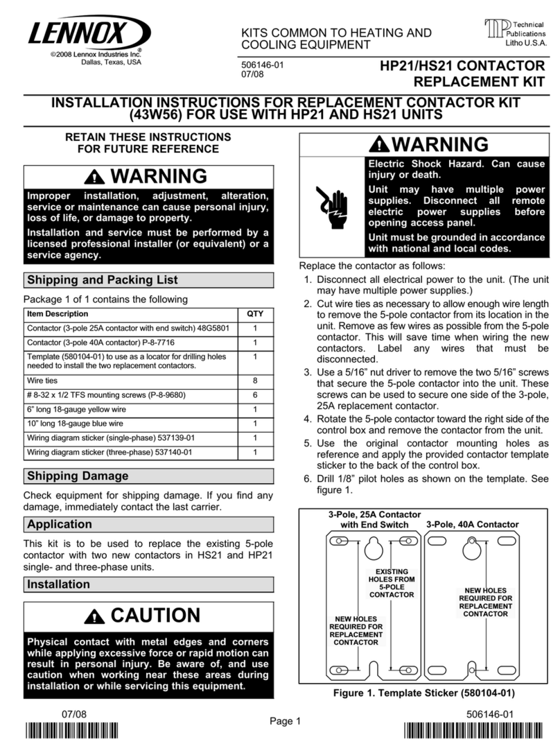
GCS16 unit components are shown in figures1, 2 and 3.
A-Control Box Components
GCS16H control box is shown in figure 4. The control box
is located in the upper portion of the compressor compart
ment behind the compressor compartment access panel.
Note that the burner ignition control is located inside the
control box (not in the heating compartment). The con
denser fan has its own access panel located on the oppo
site side of the unit.
GCS16R-411 and GCS16-410 control box is shown in fig
ure 5. GCS16R-511/651 and GCS16-510/650 control box
is shown in figure 6. In both units, the control box is lo
cated in the heating compartment behind the heating
compartment access panel. Note that the compressor
contactor is located behind a separate access panel on
the mullion adjacent to the compressor compartment ac
cess panel. The condenser fan can be accessed by re
moving the fan grill located on top of the unit.
The indoor blower access panel (all units) is located on the
opposite side of the unit from the heating compartment ac
cess. Figure 1 shows typical blower compartment access.
Page 12
FIGURE 4
GCS16H CONTROL BOX
IGNITION CONTROL
CONTACTOR
TRANSFORMER
COMPRESSOR
RUN CAPACITOR
COMBUSTION AIR
BLOWER RELAY BLOWER RELAY
FIGURE 5
BLOWER/LIMIT
CONTROL S47
COMPRESSOR
CONTACTOR
INDOOR BLOWER RELAY K20
(HEATING SPEED)
460V & 575V UNITS ONLY
TERMINAL STRIP TB1
(GCS16 ONLY)
TRANSFORMER T1
TRANSFORMER T3
GCS16R-411 / GCS16-410 CONTROL BOX
INDOOR BLOWER RELAY K3
(COOLING SPEED)
COMBUSTION AIR BLOWER
RELAY K13
FUSE F1
460V & 575V UNITS ONLY
Page 13
START
CAPACITOR
(SINGLEPHASE ONLY)
TRANSFORMER T1
POTENTIAL RELAY K31
(SINGLEPHASE ONLY)
TERMINAL STRIP TB1
(GCS16 ONLY)
TRANSFORMER T4
TRANSFORMER T3
GCS16R-511/651 / GCS16-510/650 CONTROL BOX
FIGURE 6
INDOOR BLOWER RELAY K20
(HEATING SPEED)
460V & 575V UNITS ONLY
BLOWER/ LIMIT
CONTROL S47
COMBUSTION AIR BLOWER
RELAY K13
INDOOR BLOWER RELAY K3
(COOLING SPEED)
FUSE F1
460V & 575V UNITS ONLY
COMPRESSOR
CONTACTOR
1-Terminal Strip TB1
All GCS16 commercial units are equipped with a low volt
age terminal strip (TB1). The strip is used for making up all
indoor thermostat and outdoor unit low voltage control wir
ing connections (see figures 5 and 6). The terminal strip is
located in the burner compartment on the outside panel of
the control box.
2-Transformer T1
All GCS16 series units use a single line voltage to 24VAC
transformer mounted in the control box. The transformer
supplies power to control circuits in the unit. Transformers
are rated at 45VA. 208/230 (P) voltage transformers use
two primary voltage taps as shown in figure 7.
FIGURE 7
BLUE
YELLOW
ORANGE
RED
BLACK
240 VOLTS
208 VOLTS
PRIMARY SECONDARY
208 / 240 VOLT TRANSFORMER
3-Transformer Fuse F1
208/230 (P) voltage transformers are not equipped with in
ternal secondary voltage overcurrent protection. 460 (G)
voltage and 575 (J) voltage transformers are equipped
with an integral fuse connected in series with the blue sec
ondary voltage wire. The fuse may be accessed outside
the transformer and is rated 2.5A for 460 volt units and
3.5A for 575 volt units.
4-Transformer T3
460 (G) and 575 (J) voltage units use a line voltage to
230V autotransformer to power the combustion air blower.
The autotransformer is connected directly to line voltage
and is powered at all times. It has an output rating of 0.5A.
5-Transformer T4
575 (J) voltage units use a line voltage to 460V autotrans
former to power the indoor blower. This autotransformer is
also connected directly to line voltage and is powered at all
times. It has a maximum VA rating of 3.4A.
Page 14
6-Cooling Contactor K1
K1 is a 24V to line voltage contactor used to energize the
compressor and condenser fan in response to thermostat
demand. Threephase units use threepoledoublebreak
contactors. Singlephase units use singlepole contac
tors.
DANGER - ALL SINGLEPHASE UNITS USE
SINGLEPOLE CONTACTORS. ONE LEG OF COM
PRESSOR, CAPACITOR AND CONDENSER FAN
ARE CONNECTED TO LINE VOLTAGE AT ALL
TIMES. POTENTIAL EXISTS FOR ELECTRICAL
SHOCK RESULTING IN INJURY OR DEATH. RE
MOVE ALL POWER AT DISCONNECT BEFORE
SERVICING.
NOTE - Contactor K1 is energized by the thermostat
control system. Depending on the control system
installed, the contactors may or may not be immediate
ly energized upon demand. Refer to the operation se
quence for the control system installed.
7-Indoor Blower Relay K3 (Cooling Speed)
208/230 volt units use a single 2PDT relay to energize the
indoor blower motor. 460 volt and 575 volt units use a
single 3PDT relay. The relay coil is energized by blower
demand from indoor thermostat terminal G" (cooling de
mand or fan switch in ON" position). When the coil is ener
gized, a set of N.O. contacts closes to energize the blower
motor on high speed. When deenergized, a set of N.C.
contacts allows the fan / limit control relay to energize the
blower on heating speed (refer to unit wiring diagram).
460 (G) and 575(J) voltage units use a unique blower mo
tor. The motor utilizes a set of N.C. relay K3 contacts to
complete an internal circuit when the motor is on low or
medium (heating) speed.
8-Potential Relay K31
Relay K31 is used in singlephase -510 and -650 units only
and is located in the control box. It is a potential relay
which controls the operation of the starting circuit. The
relay is normally closed when the compressor (contactor
K1) is deenergized. Capacitor (C7) is connected to a set
of N.C. K31 contacts and is used to assist the compressor
in starting. When K1 energizes, the compressor immedi
ately begins startup. K31 remains deenergized during
compressor startup and the start capacitor (C7) remains
in the circuit. As the compressor gains speed K31 is ener
gized by electromotive forces generated by the compres
sor. When K31 energizes, its contacts open to take the
start capacitor out of the circuit.
9-Combustion Air Blower Relay K13
Relay K13 is a DPDT relay located inside the control box.
K13 is energized by heating demand from the thermostat
and is energized throughout the heating demand. When
energized, K13 normally open contacts close to energize
the combustion air blower and begin a heating sequence.
A differential pressure prove" switch connected to the
combustion air blower in turn energizes the ignition control
and gas valve. A separate set of K13 contacts close to en
ergize the economizer.
10-Indoor Blower Relay K20
(Heating Speed)
used in 460V and 575V units only
Relay K20 is a 3PDT relay also located in the control box.
Relay K20 is energized when timedelay relay K25 closes.
K20 is used to energize the blower on heating speed.
When relay K20 is energized, a set of contacts close to en
ergize the blower.
Page 15
B-Heating Components (Figure 8)
CONVERTIBLE CABINET HEATING COMPONENTS
HORIZONTAL ONLY CABINET HEATING COMPONENTS
BURNER PLATE
GAS VALVE
GAS MANIFOLD
(may be surrounded by burn
er enclosure - see below)
SPARK/SENSOR
ELECTRODE
ASSEMBLY
BLOWER/LIMIT
CONTROL
BURNER
DIFFERENTIAL
PRESSURE SWITCH
COMBUSTION AIR BLOWER
IGNITION CONTROL
COMBUSTION AIR TRANSITION
BLOWER/LIMIT
CONTROL
DIFFERENTIAL
PRESSURE SWITCH
SPARK/SENSOR
ELECTRODE
ASSEMBLY
BURNER ENCLOSURE
(not included on all units)
SIGHT GLASS
(not included on all units)
BURNER PLATE
GAS VALVE
GAS MANIFOLD
COMBUSTION AIR BLOWER
IGNITION CONTROL
BURNER ENCLOSURE
AIR INTAKE
BURNER
DIFFERENTIAL PRESSURE
SWITCH HOSE
IMPORTANT-HOSE MUST BE
POSITIONED SO CONDENSATE
CAN DRAIN
DIFFERENTIAL PRESSURE
SWITCH HOSE
IMPORTANT-HOSE MUST BE
POSITIONED SO CONDENSATE
CAN DRAIN
ROLLOUT SWITCH
LOCATION FOR ALL UNITS
(HORIZONTAL AND CONVERTIBLE)
WITHOUT BURNER ENCLOSURE
ROLLOUT SWITCH
LOCATION FOR ALL UNITS
(HORIZONTAL AND
CONVERTIBLE) WITH
BURNER ENCLOSURE
FIGURE 8
PRODUCED AFTER NOVEMBER 1,1989
Page 16
FIGURE 9
GCS16 HEAT EXCHANGE ASSEMBLY
ORIFICE
BURNER PLATE
HELICAL ALUMINIZED
STEEL TUBE
EXHAUST
(SECONDARY)
CAST IRON
CYLINDRICAL
HEAT EXCHANGER
(PRIMARY)
BURNER CONE
GASKET
BURNER
HEAT FINS
EXHAUST PORT
NON-ADJUSTABLE
ENDCAP
AIR OPENINGS
INSULATION
FLAME SPREADER
-50, -75, ONLY
RETENTION RING
1-Heat Exchanger (Figure 9)
All units use a cast iron cylindrical heat exchanger (prima
ry) encircled by helical aluminized steel tube exhaust (sec
ondary). Heat is transferred to the airstream from all sur
faces of the primary and secondary. A single inshot burner
is directed at a spreader in the heat exchanger and a com
bustion air blower is used to pull combustion air through
the heat exchanger. Heat exchangers are configured as
shown in Table 1.
TABLE 1
Btuh Heat Exchanger
(Primary)
Size
Heat Exchanger
(Secondary)
No. of Wraps Around
Primary
50,000
75,000
100,000
125,000
Small
Large
2
3
4
5
Small
Large
2-Burner Assembly (Figures 10 and 11)
The burner is controlled by the spark electrode, flame
sensing electrode, gas valve GV1 and combustion air
blower B6. The spark electrode, flame sensing electrode
and gas valve GV1 are directly controlled by ignition con
trol A3. Ignition control A3 is controlled by combustion air
blower B6. Combustion air blower B6 is controlled by heat
ing demand from the thermostat or control system.
The burner is factory set and does not require adjustment.
Burner end caps (if used - see figure 9 ) are non-adjust
able. Flame can be viewed through air holes in the burner
plate. A peep hole is provided in the burner access panel
on units without a burner enclosure. If a burner enclosure
is used, a flame viewing glass is provided in the enclosure.
Combustion takes place at the heat exchanger entrance.
Combustion air is pulled through the burner by the com
bustion air blower (B6). Air is mixed with fuel in the burner.
The mixture is then ignited by the spark electrode and the
resultant flame is directed against a flame spreader. The
spreader disrupts and spreads the flame. The burner cone
surrounding the entrance to the heat exchanger directs
additional combustion air into the flame. A flame retention
ring located in the burner end is used to keep flame from
lifting off the burner head. As hot exhaust gases are drawn
through the heat exchanger by the combustion air blower,
exhaust gases are expelled from the heat exchanger sec
ondary and fresh air/gas mixture is drawn in through the
burner and supply air holes. Supply air blower B3, con
trolled by blower relay K25 forces air across all surfaces of
the heat exchanger primary and secondary to extract the
heat of combustion.
Page 17
a-Burners
All units use an inshot burner (see figures 10 and 11). A
flame retention ring located in the burner end is used to
keep flame from lifting off the burner. The flame is aimed at
a round flame spreader located in the combustion cham
ber. The spreader distributes the flame evenly around the
circumference of the heat exchanger. Burners in 50,000
and 75,000 Btuh heat exchangers use a separate nonad
justable endcap (see figure 10). Burners in 100,000 and
125,00 Btuh heat exchangers do not use an endcap (see
figure 11).
INSHOT BURNER
50,000 and 75,000 Btuh HEAT EXCHANG
ERS
FIGURE 10
FLAME
RETENTION
RING
BURNER
SEPARATE
NON-ADJUSTABLE
ENDCAP ORIFICE
INSHOT BURNER
100,000 and 125,000 Btuh HEAT EXCHANG
ERS
FIGURE 11
FLAME
RETENTION
RING BURNER
ORIFICE
b-Orifice
All GCS16 units use an orifice which is precisely matched
to the burner input. The burner is supported by the orifice
and will easily slide off for service.
Each orifice and burner are sized specifically to the unit.
Refer to Lennox Repair Parts Listing for correct sizing in
formation.
3-Burner Enclosure
The following units are equipped with a burner enclosure
surrounding the burner assembly:
GCS16R-510-125, GCS16-510-125,
GCS16R-650-125, GCS16-650-125,
GCS16R-411-100, & GCS16H-311-75.
The enclosure is used to reduce sound levels in the burner
area. The enclosure consists of a metal wrapper sur
rounding the burner assembly and a glass flame viewing
window (see figure 12).
The burner can be inspected and the spark/sensor elec
trode removed by removing the burner enclosure sight
glass plate. If the burner must be removed or the orifice
accessed, the burner enclosure must be removed. Burner
enclosure and burner removal is detailed in the mainte
nance section of this manual.
Units equipped with burner enclosure are also equipped
with flame rollout switch. The switch provides unit protec
tion by shutting down the unit when flame rollout is sensed.
FIGURE 12
GCS16/GCS16R/GCS16H
BURNER ENCLOSURE
FLAME
ROLLOUT
SWITCH
SIGHT
GLASS
AIR INTAKE
Page 18
4-Blower / Limit Control:
High Temperature Limit S10,
Blower Control K25
A combination blower/limit control with a bimetal sure
start heater (figure 13) is used to control blower operation
and protect unit from high temperature operation. It is lo
cated in the upper end of the heating vest panel. The blow
er control heater is a resistive type bemetal heat relay
(K25) used to reduce the time between blower demand
and blower startup. It is energized with the heating de
mand.
Internal contacts K25 are used to coordinate blower op
eration with burner operation. The N.O. contacts are actu
ated by a bimetal spring when temperature rise in the heat
ing compartment (in addition to heat added by the sure
start heater) is sufficient. The blower cycles on 20 to 90
seconds after the start of a heating demand and cycles off
120 to 240 seconds after heat demand is satisfied (when
bimetal swtich cools). Ontime will vary, depending on the
voltage applied to the bimetal heater and on the tempera
ture surrounding the K25 switch. The relay is SPST.
The blower control has a factory off setting of 90F. This
control can be field adjusted. In some cases, an unusual
duct design can cause the indoor blower to cycle on after
the heat demand is satisfied. If this situation occurs, the
Fan Off" setting on the blower/limit control should be set
below 90F. See figure 13.
NOTE - Blower OFF" settings above 90Fwill cause
the blower to recycle frequently (after a heating cycle)
due to residual heat in the heat exchange assembly.
Blower OFF" settings above 90Fmay also cause
nuisance trips of secondary limit S10.
Adjustment procedure is outlined in Heating System Ser
vice Checks" section.
Primary limit S10 contacts deenergize the ignition control
when excessive temperature is reached in the blower
compartment. The N.C. limit is a SPST autoreset switch.
It is fixed in position for a maximum discharge air tempera
ture. The limit is factory preset to trip on a temperature rise
and automatically reset on a temperature fall. On a tem
perature rise terminals 1-3 open to deenergize the igni
tion circuit. Table 2 shows factory settings. This is a safety
shutdown function of the unit.
TABLE 2
LIMIT CONTROL S10
Unit Input
Thousand
Btuh
High Limit
Cutout
+ 10F
50
75
100
510-125
160F
170F
150F
170F
650-125 160F
FIGURE 13
HONEYWELL BLOWER/LIMIT CONTROL
BLOWER SETTING
POINTERS LIMIT SETTING
POINTER
FIXED STOP
5-Secondary Limit S21
100,000 Btuh Heat Exchangers Only
All GCS16-410-100 and GCS16R-411-100 units are
equipped with a secondary high temperature limit located
on the blower scroll (see figure 14). The limit is a SPST
autoreset temperature which opens (terminals 1-3) on a
temeprature rise. It is electrically connected in series with
the ignition control. The limit is used to deenergize the
ignition control and shut down the unit when temperature
in the blower scroll becomes too high. The limit is factory
preset to open at 170F+5F on a temperature rise and
close at 130F+10F on a temperature fall. It is not adjust
able. This is a safety shutdown function of the unit.
Page 19
FIGURE 14
SECONDARY LIMIT
GCS16-410-100 AND GCS16R-411-100 ONLY
BLOWER SECONDARY LIMIT
LOCATION
6-Flame Rollout Switch S47
Flame rollout switch S47 is a high temperature limit lo
cated just above the burner air intake opening in the burn
er enclosure (see figure 12). The limit is a N.C. SPST re
settable limit connected in series with ignition control A3.
When S47 senses flame rollout, the ignition control imme
diately stops ignition and closes the gas valve. The switch
is factory set and cannot be adjusted.
Initially, only units equipped with a burner enclosure were
equipped with rollout switch S47 (see section 3- Burner
Enclosure and figure 12). In November 1989, rollout
switch was added to all units. It is an A.G.A. mandated re
quirement on all gas furnaces produced after that date. In
all 75,000, 100,000 and 125,000 Btuh heat exchanger
units produced after November 1989, the switch is
installed in a burner enclosure as shown in figure 12. In all
50,000 Btuh heat exchanger units produced after Novem
ber 1989, the switch is installed as shown in figure 8.
7-Combustion Air Prove Switch S18
The combustion air prove switch (S18) is a SPST N.O. dif
ferential pressure switch used to monitor combustion air
blower operation. A flexible hose connects one side of the
switch to the blower housing. The other side of the switch
is open to the atmosphere. The switch is wired in series
with ignition control A3. Prove switch S18 closes when the
combustion air blower reaches full speed to allow the igni
tion control to energize. This proves that the combustion
air blower is operating and allows the heating cycle to con
tinue.
The combustion air prove switch is factory set and is not
adjustable. Factory settings are shown in Table 3.
COMBUSTION AIR PROVE SWITCH
FACTORY SETTING
TABLE 3
Unit inches w.c.
N.O., closes on pressure drop
GCS16H-261
GCS16H-311
0.45 + 0.05
0.65 + 0.05
GCS16-411/413-100 0.45 + 0.05
GCS16-511/513-125 0.90 + 0.05
GCS16-651/653-75
GCS16R-650-125
0.45 + 0.05
0.90 + 0.05
GCS16R-411-100 0.65 + 0.05
GCS16-411/413-50 0.45 + 0.05
GCS16R-411-50 0.45 + 0.05
GCS16R-651-75 0.45 + 0.05
GCS16R-511-125 0.90 + 0.05
GCS16-651/653-125 0.90 + 0.05
8-Combustion Air Blower B6
Combustion air blower B6 provides fresh air to the burner
while clearing the combustion chamber of exhaust gases.
The blower begins operating immediately upon receiving
a thermostat demand and is deenergized immediately
when thermostat demand is satisfied.
Blowers on 50K, 75K and 100K Btuh heat exchangers are
manufactured by Lennox and can be disassembled for
cleaning. Blowers on 125K Btuh heat exchangers are fac
tory assembled as a unit and cannot be disassembled for
cleaning.
Combustion air blower specifications are shown in table 4.
All combustion air blower motors are sealed and cannot be
oiled.
The tube connecting the switch to the blower flue box must
be sloped in a manner that will prevent condensate from
collecting in the tube. It is normal for a small amount of
condensate to form in the tube during unit operation. The
tube and switch must be allowed to drain accumulated
condensate between thermostat demands. If the tube is
positioned so that accumulated condensate is trapped in
the tube, the unit may run improperly or may lock out.
TABLE 4
COMBUSTION AIR BLOWER
Unit Input
Btuh Type HP RPM
Volts/
phase Bearings Misc.
50K
75K
100K
125K
208/
230/1
Shaded
Pole
1-1/2
Stack
1/25 3200 Ball
Requires
T3 when
used in
460/575
volt units
208/
230/1
Requires
T3 when
used in
460/575
volt units
Ball32001/10PSC
Page 20
9-Flue Vent (Figure 15)
WARNING - VENT CAP ASSEMBLY MUST BE
INSTALLED WITHOUT MODIFICATION. ANY MOD
IFICATION TO THE VENT CAP ASSEMBLY OR
FAILURE TO INSTALL ASSEMBLY CAN RESULT
IN IMPROPER OPERATION AND WILL VOID THE
AGA/CGA CERTIFICATION OF THE UNIT.
CAUTION - DO NOT START OR OPERATE UNIT
UNLESS VENT CAP IS IN PLACE.
FIGURE 15
VENT
GASKET
VENT CAP
ASSEMBLY
TYPICAL FLUE VENT INSTALLATION
GCS16H-261/311 SHOWN
FOR ILLUSTRATION ONLY
NOT DRAWN TO SCALE
10-Burner Access Wind and Rain Shield
(Figure 16)
WARNING - THE BURNER ACCESS PANEL WIND
AND RAIN SHIELD MUST BE INSTALLED WITH
OUT MODIFICATION. IF EITHER THE BURNER AC
CESS PANEL OR WIND AND RAIN SHIELD IS NOT
INSTALLED OR IS MODIFIED, IMPROPER UNIT
OPERATION CAN RESULT AND AGA/CGA CER
TIFICATION OF UNIT WILL BE VOID.
BURNER ACCESS
PANEL
BURNER ACCESS
WIND SHIELD
SECURE WITH
FOUR SCREWS
(Provided)
UNIT
FIGURE 16
RAIN SHIELD
GCS16-410 THROUGH 650 SHOWN
TYPICAL BURNER ACCESS COVER
AND RAIN SHIELD
11-Combustion Air Blower Capacitor C3
All units equipped with 125K Btuh heat exchanger use a
singlephase PSC motor to power the combustion air
blower. A single run capacitor is mounted on the motor.
The capacitor is rated 4mfd at 370VAC.
All other heat exchanger sizes use a shaded pole motor to
power the combustion air blower. Shaded pole motors do
not require a run capacitor.
12-Gas Valve GV1
Gas valve GV1 is a singlestage redundant valve
manufactured by Honeywell. In 50,000 and 75,000 Btuh
heat exchangers, the valve is slow opening (1-10 sec
onds). 100,000 and 125,000 Btuh heat exchangers use
quick opening gas valves (1 sec. or less). On a call for
heat, the valve is energized by the ignition control simulta
neously with the spark electrode. When the valve is de
energized, it closes in 1/2 to 3 seconds. A manual shutoff
knob is provided on the valve for shutoff. Figure 17 shows
gas valve components. Table 5 shows factory gas valve
regulation for GCS16 series units.
TABLE 5
GAS VALVE REGULATION
Unit Input
K Btuh
Maximum
Inlet Pressure
in. W.C.
Operating Pressure
(outlet) in. W.C.
50
75
100
125
21.0
21.0
3.5 +0 -0.3
3.5 +0 -0.3
21.0 3.5 +0 -0.3
21.0 2.7 +0 -0.3
Natural L.P.
10.5
10.5
9.5
10.0
FIGURE 17
GAS VALVE GV1
INLET
PRESSURE
TAP
PRESSURE
REGULATOR
(under cap)
OUTLET
PRESSURE
TAP
W1
TERMINAL
C
TERMINAL
ON/OFF
KNOB
OUTLET GROUND
TERMINALS

Other manuals for GCS16 Series

1

This manual suits for next models

12

Other Lennox Industrial Equipment manuals

Lennox 10GCS Series User manual

Lennox

Lennox 10GCS Series User manual

Lennox SYSTEMA EOLO LXC 50 User manual

Lennox

Lennox SYSTEMA EOLO LXC 50 User manual

Lennox G26 Series User manual

Lennox

Lennox G26 Series User manual

Lennox TSA S4 Series User manual

Lennox

Lennox TSA S4 Series User manual

Lennox COMFAIR-HH User manual

Lennox

Lennox COMFAIR-HH User manual

Lennox TAA Series Installation and operation manual

Lennox

Lennox TAA Series Installation and operation manual

Lennox EL195UHNE Series User manual

Lennox

Lennox EL195UHNE Series User manual

Lennox HP21 User manual

Lennox

Lennox HP21 User manual

Lennox G21Q3-40 Installation and operation manual

Lennox

Lennox G21Q3-40 Installation and operation manual

Lennox OHR23 Series User manual

Lennox

Lennox OHR23 Series User manual

Popular Industrial Equipment manuals by other brands

Fein GBA 18V manual

Fein

Fein GBA 18V manual

Staubli CombiTac Assembly instructions

Staubli

Staubli CombiTac Assembly instructions

SCHUNK GSM-Z Series Assembly and operating manual

SCHUNK

SCHUNK GSM-Z Series Assembly and operating manual

Germfree VersaFlow user manual

Germfree

Germfree VersaFlow user manual

Kval Edge-SS Operation & service manual

Kval

Kval Edge-SS Operation & service manual

Acoustic Signature STORM 2018 instruction manual

Acoustic Signature

Acoustic Signature STORM 2018 instruction manual

Afag PEL20 Assembly and operating instructions

Afag

Afag PEL20 Assembly and operating instructions

ABB TPL67-C80 Operation manual

ABB

ABB TPL67-C80 Operation manual

Mark 7 Primer Xpress instruction manual

Mark 7

Mark 7 Primer Xpress instruction manual

Koehler K463XX Operation and instruction manual

Koehler

Koehler K463XX Operation and instruction manual

Invertek Drives Optidrive E3 ODE-3 Series user guide

Invertek Drives

Invertek Drives Optidrive E3 ODE-3 Series user guide

Amtrol THERM-X-TROL ST-20V-C Installation & operation instructions

Amtrol

Amtrol THERM-X-TROL ST-20V-C Installation & operation instructions

RHINO RHINO 2409 Assembly manual

RHINO

RHINO RHINO 2409 Assembly manual

Schulte FM-350 Operator's manual

Schulte

Schulte FM-350 Operator's manual

ABB HT603383 Operation manual

ABB

ABB HT603383 Operation manual

CLEAN ROOM DEVICES CRD600 Operation manual

CLEAN ROOM DEVICES

CLEAN ROOM DEVICES CRD600 Operation manual

Global WF 1767-70 Series Instruction & parts manual

Global

Global WF 1767-70 Series Instruction & parts manual

Crystal SilentShake TR-01A manual

Crystal

Crystal SilentShake TR-01A manual

manuals.online logo
manuals.online logoBrands
  • About & Mission
  • Contact us
  • Privacy Policy
  • Terms and Conditions

Copyright 2025 Manuals.Online. All Rights Reserved.