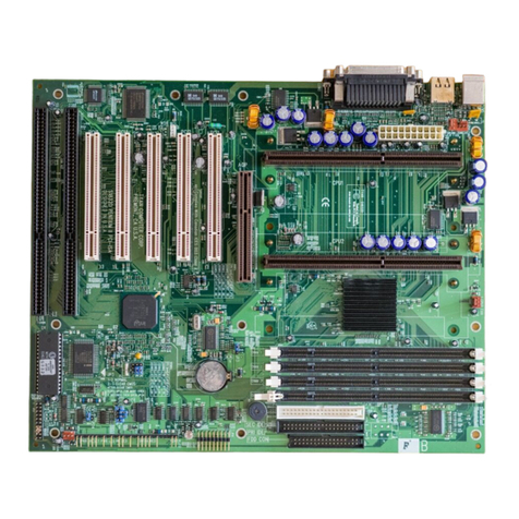
Intel DK440LX User manual

DK440LX
Motherboard
Product Guide
Order Number: 685890-001

Revision History
Revision Revision History Date
-001 First release of the DK440LX Motherboard Product Guide. October 1997
Information in this document is provided in connection with Intel products. No license, express or implied, by estoppel or
otherwise, to any intellectual property rights is granted by this document. Except as provided in Intel's Terms and Conditions of
Sale for such products, Intel assumes no liability whatsoever, and Intel disclaims any express or implied warranty, relating to
sale and/or use of Intel products including liability or warranties relating to fitness for a particular purpose, merchantability, or
infringement of any patent, copyright or other intellectual property right. Intel products are not intended for use in medical, life
saving, or life sustaining applications.
Intel retains the right to make changes to specifications and product descriptions at any time, without notice.
The DK440LX motherboard may contain design defects or errors known as errata which may cause the product to deviate from
published specifications. Current characterized errata are available on request.
Copies of documents which have an ordering number and are referenced in this document, or other Intel literature, may be
obtained from:
Intel Corporation
P.O. Box 7641
Mt. Prospect, IL 60056-7641
or call in North America 1-800-879-4683, Europe 44-0-1793-431-155, France 44-0-1793-421-777,
Germany 44-0-1793-421-333, other Countries 708-296-9333.
†Third-party brands and names are the property of their respective owners.
†† Wake on LAN is a trademark of IBM Corporation.
Copyright Intel Corporation, 1997

iii
Contents
1 Motherboard Features
Microprocessor......................................................................................................................7
Microprocessor Upgrades.....................................................................................................7
Main Memory ......................................................................................................................10
Second-level Cache Memory..............................................................................................10
PCI Enhanced IDE Interface...............................................................................................10
LS-120 Diskette Support.....................................................................................................10
Input/Output (I/O) Controller................................................................................................10
Real-Time Clock..................................................................................................................11
Universal Serial Bus Support..............................................................................................11
Accelerated Graphics Port (A.G.P.) Support.......................................................................12
SCSI Support......................................................................................................................12
Basic Input/Output System (BIOS)......................................................................................12
BIOS Upgrades..........................................................................................................12
PCI Auto Configuration...............................................................................................12
IDE Auto Configuration...............................................................................................13
ISA Plug and Play Capability......................................................................................13
Security Passwords....................................................................................................13
Add-in Card Slots................................................................................................................13
Hardware Monitor................................................................................................................14
Wake on LAN Connector ....................................................................................................14
Battery ................................................................................................................................14
Speaker ..............................................................................................................................14
Optional Features ...............................................................................................................15
Networking .................................................................................................................15
Audio Subsystem .......................................................................................................15
Onboard Serial Port B Connector...............................................................................15
2 Installing and Replacing Motherboard Components
Before You Begin................................................................................................................17
How to Install and Remove the Motherboard......................................................................18
How to Install the Processor Retention Mechanism............................................................19
Processor Upgrades ...........................................................................................................20
Upgrading a Single Processor....................................................................................20
Upgrading from Single to Dual Processors.................................................................20
Upgrading Dual Processors........................................................................................21
How to Remove a Processor ..............................................................................................21
How to Install the Termination Card....................................................................................22
How to Remove the Termination Card................................................................................23
How to Install a Single Processor .......................................................................................24
How to Install a Second Processor.....................................................................................25
How to Set the Processor Speed........................................................................................27
How to Install Memory.........................................................................................................28
How to Remove Memory.....................................................................................................30

Contents
iv
How to Replace the Battery ................................................................................................31
How to Clear Passwords.....................................................................................................33
3 Using the Setup Program
Setup Program Modes........................................................................................................35
Setup Menus.......................................................................................................................36
Setup Program Navigation..................................................................................................36
Maintenance Menu .............................................................................................................37
Main Menu..........................................................................................................................37
Floppy Options Submenu...........................................................................................38
IDE Device Configuration Submenus.........................................................................39
Advanced Menu..................................................................................................................40
Resource Configuration Submenu .............................................................................41
Peripheral Configuration Submenu ............................................................................42
Keyboard Configuration Submenu.............................................................................44
Video Configuration Submenu ...................................................................................44
DMI Event Logging Submenu ....................................................................................45
Security Menu.....................................................................................................................45
Power Menu........................................................................................................................46
Boot Menu ..........................................................................................................................47
Hard Drive Submenu..................................................................................................48
Removable Devices Submenu...................................................................................48
Exit Menu............................................................................................................................48
4 SCSI Support
SCSI Device Support..........................................................................................................49
Termination, Internal SCSI Devices ...........................................................................49
Termination, External SCSI Devices ..........................................................................49
RAID
port
Connector...................................................................................................50
Using the SCSI
Select
Utility................................................................................................50
Main Screen...............................................................................................................51
Configuration Menu....................................................................................................51
Boot Device Configuration..........................................................................................52
SCSI Device Configuration Menu...............................................................................52
Advanced Configuration Options................................................................................54
Using the SCSI Disk Utilities...............................................................................................56
Format Disk................................................................................................................56
Verify Disk Media .......................................................................................................56
5 Upgrading the BIOS
Preparing for the Upgrade ..................................................................................................57
Obtaining the BIOS Upgrade File...............................................................................57
Recording the Current BIOS Settings.........................................................................57
Creating a Bootable Floppy Disk................................................................................58
Creating the BIOS Upgrade Floppy Disk....................................................................58
Upgrading the BIOS............................................................................................................58
Recovering the BIOS..........................................................................................................59
Changing the BIOS Language............................................................................................60

DK440LX Motherboard Product Guide
v
6 Technical Reference
Motherboard Connectors ....................................................................................................61
Front Panel Connectors......................................................................................................66
Motherboard Resources......................................................................................................68
Memory Map ..............................................................................................................68
DMA Channels...........................................................................................................68
I/O Map .....................................................................................................................69
PCI Configuration Space Map....................................................................................71
Interrupts....................................................................................................................71
A Error Messages
BIOS Beep Codes...............................................................................................................73
BIOS Error Messages.........................................................................................................73
B Regulatory and Integration
Information
Regulatory Requirements ...................................................................................................75
Safety Standards........................................................................................................75
Electromagnetic Compatibility (EMC) Regulations.....................................................76
Product Certification Markings....................................................................................76
Installation Precautions.......................................................................................................77
Installation Instructions .......................................................................................................77
Ensure Electromagnetic Compatibility (EMC).............................................................77
Ensure Host Computer and Accessory Module Certifications....................................78
Prevent Power Supply Overload ................................................................................78
Place Battery Marking on the Computer.....................................................................79
Use Only for Intended Applications............................................................................79
Figures
1. Motherboard Layout.....................................................................................................8
2. Back Panel Connectors................................................................................................9
3. Mounting Screw Holes ...............................................................................................18
4. Installing the Processor Retention Mechanism ..........................................................19
5. Removing a Processor...............................................................................................21
6. Installing the Termination Card ..................................................................................22
7. Removing the Termination Card.................................................................................23
8. Installing a Single Processor......................................................................................24
9. Installing a Second Processor....................................................................................26
10. Configuration Jumper Block.......................................................................................27
11. Location of DIMM Sockets .........................................................................................29
12. Installing a DIMM........................................................................................................30
13. Replacing the Battery.................................................................................................32
14. Motherboard Connectors............................................................................................61
15. Front Panel Connectors .............................................................................................66

Contents
vi
Tables
1. Jumper Settings for Setup Program Modes ...............................................................35
2. Setup Menu Bar.........................................................................................................36
3. Setup Function Keys..................................................................................................36
4. Maintenance Menu.....................................................................................................37
5. Main Menu .................................................................................................................37
6. Floppy Options Submenu...........................................................................................38
7. IDE Device Configuration Submenus.........................................................................39
8. Advanced Menu.........................................................................................................40
9. Resource Configuration Submenu.............................................................................41
10. Peripheral Configuration Submenu............................................................................42
11. Keyboard Features Submenu ....................................................................................44
12. Video Configuration Submenu ...................................................................................44
13. DMI Event Logging Submenu ....................................................................................45
14. Security Menu............................................................................................................45
15. Power Menu...............................................................................................................46
16. Boot Menu..................................................................................................................47
17. Hard Drive Submenu..................................................................................................48
18. Removable Devices Submenu...................................................................................48
19. Exit Menu...................................................................................................................48
20. Overview of the SCSI
Select
Keys..............................................................................50
21. Chassis Security Connector (J0A1)............................................................................62
22. ATAPI CD Audio Connector (J1F1)............................................................................62
23. ATAPI-Style Telephony Connector (J0E1).................................................................62
24. ATAPI-Style Line In Connector (J0F2).......................................................................62
25. 2 mm CD Audio Connector (J1E1).............................................................................62
26. MIDI/Game Port Connector (J2E2) ............................................................................63
27. Front Chassis 2 Fan Connector (J12B2)....................................................................63
28. CPU 2 Fan Connector (J3F2).....................................................................................63
29. Rear Chassis Fan Connector (J1M1).........................................................................63
30. CPU Fan 1 Connector (J2E1) ....................................................................................64
31. Front Chassis 1 Fan Connector (J12A1)....................................................................64
32. Hard Drive LED Input Connector (J10A1)..................................................................64
33. Hard Drive LED Input Connector (J11B1)..................................................................64
34. Wake on LAN Connector (J6D1)................................................................................64
35. Wake-on-Modem Connector (J9A1)...........................................................................64
36. Auxiliary Power Supply Connector (J1M2).................................................................65
37. Sleep LED Header (J12D1)........................................................................................65
38. Front Panel Connectors .............................................................................................67
39. Memory Map ..............................................................................................................68
40. DMA Channels...........................................................................................................68
41. I/O Map ......................................................................................................................69
42. PCI Configuration Space Map....................................................................................71
43. Interrupts....................................................................................................................71
44. Beep Codes ...............................................................................................................73
45. BIOS Error Messages ................................................................................................73
7
1 Motherboard Features
This chapter describes the features of the DK440LX motherboard. The remaining chapters explain
how to:
• Add or upgrade components like processors or memory
• Use the BIOS Setup program and the SCSISelect†utility to modify the motherboard’s
configuration
• Upgrade the BIOS
Figure 1 shows the location of components on the motherboard and Figure 2 shows the details of
the back panel connectors.
Microprocessor
The DK440LX motherboard supports 233 MHz, 266 MHz, and 300 MHz Pentium®II processors.
The motherboard is designed to operate with one or two processors. Processors are not included
with the DK440LX motherboard and must be purchased separately.
Each processor is packaged in a Single Edge Contact (S.E.C.) cartridge. The S.E.C. cartridges
mount in a dual-processor retention mechanism which is provided with Intel boxed motherboards.
Microprocessor Upgrades
If your motherboard has one processor, you can upgrade the computer by replacing this processor
with a faster processor or by installing a second processor. If your motherboard has two
processors, you can upgrade the computer by installing two faster processors.
Computers with two processors must have an operating system (such as Windows†NT†or UNIX†)
that supports multiple processors.
If you are installing two processors, the following values must be identical for both processors:
• L2 cache size and type (ECC or non-ECC)
• Operating voltages
• Maximum bus and core frequencies
The core stepping value may differ by one step, such as C0 to C1. These values can be determined
by checking the parameters of the s-spec number. The s-spec number is a five-character code, for
example, SL28R, printed on the top edge of the S.E.C.
For information about s-spec parameters, refer to the Pentium II processor quick reference guide at
the Intel developer’s web site.
CAUTION
If the operating voltages do not match, the computer will not boot.

Motherboard Features
8
OM06320
V U TWXY
I
J
L
M
N
K
HA D
II
JJ
EE
DD
CC
Z
HH
FF
GG
S
RQP O
F
G
E
B C
AA
BB
Figure 1. Motherboard Layout
A. Onboard serial port 2 connector (optional) S. Ultra-wide (16-bit) SCSI connectors
B. Rear chassis fan connector T. Narrow (8-bit) SCSI connector
C. ATAPI CD audio connector (optional) U. Sleep LED connector
D. ATAPI-style telephony connector (optional) V. Front panel I/O connectors
E. ATAPI-style Line In connector (optional) W. HDD LED input connector (4-pin)
F. 2 mm CD audio connector (optional) X. Front chassis 2 fan connector
G. CPU 2 fan connector Y. Front chassis 1 fan connector
H. Back panel connectors Z. Speaker
I. CPU 1 fan connector AA. Battery
J. Auxillary power connector BB. HDD LED input connector (2-pin)
K. Boot processor Slot 1 connector CC. Wake-on-Modem connector
L. ATX power connector DD. Wake on LAN†† connector
M. Application processor Slot 1 connector EE. SCSI PCI Raid
port
†connector
N. DIMM sockets FF. A.G.P. connector
O. Configuration jumper block GG. MIDI/Game Port connector (optional)
P. Secondary IDE connector HH. PCI connectors
Q. Primary IDE connector II. ISA connectors
R. Floppy drive connector JJ. Chassis security connector

DK440LX Motherboard Product Guide
9
OM06576
DF
C
HJ
A
GI
B
E
Figure 2. Back Panel Connectors
A. PS/2†connector (mouse or keyboard)
B. Parallel port connector
C. Audio Line In jack (optional)
D. PS/2 connector (mouse or keyboard)
E. USB connectors
F. Serial port A connector
G. Serial port B connector
H. LAN connector (optional)
I. Audio Line Out jack (optional)
J. Audio Mic In jack (optional)

Motherboard Features
10
Main Memory
The motherboard has four sockets for installing dual in-line memory modules (DIMMs). The
motherboard supports both extended data out (EDO) DRAM and synchronous DRAM (SDRAM).
The motherboard can operate with a minimum of 16 megabytes (MB) of memory. Maximum
memory size is 512 MB with SDRAM and 1 GB with EDO DRAM. To install memory, see
Chapter 2.
Second-level Cache Memory
The second-level cache is located on the substrate of the S.E.C. cartridge. The ECC cache includes
burst pipelined synchronous static RAM (BSRAM) and tag RAM. There are four BSRAM
components totaling 512 KB in size. Only up to 512 MB of system memory is cacheable.
PCI Enhanced IDE Interface
The PCI enhanced IDE interface handles the exchange of information between the processor and
peripheral devices like hard disks and add-in cards inside the computer. The interface supports:
• Up to four IDE devices such as hard drives
• ATAPI devices
• PIO mode 3 and PIO mode 4 devices
• Up to four PCI cards or up to two ISA cards and three PCI cards
• Logical block addressing (LBA) of hard drives larger than 528 MB and extended cylinder head
sector (ECHS) translation modes
LS-120 Diskette Support
The motherboard supports LS-120 diskette technology through its IDE interface. LS-120 diskette
technology enables users to store 120 MB of data on a single, 3.5-inch removable diskette. LS-120
technology is backward (both read and write) compatible with 1.44 MB and 720 KB DOS-
formatted diskettes and is supported by Windows 95 and Windows NT operating systems.
The motherboard allows connection of an LS-120 compatible drive and a standard 3.5-inch diskette
drive. If an LS-120 drive is connected to an IDE connector and configured as the A drive and a
standard 3.5-inch diskette drive is configured as the B drive, the standard diskette drive must be
connected to the diskette drive cable's "A" connector (the connector at the end of the cable). The
LS-120 drive can be configured as a boot device in the BIOS Setup program.

DK440LX Motherboard Product Guide
11
Input/Output (I/O) Controller
The I/O controller handles the exchange of information between the processor and external devices
like the mouse and keyboard or a printer that are connected to the computer. The controller
features the following:
• Integrated keyboard and mouse controller
• Industry standard floppy drive controller
• One multimode bidirectional parallel port
Standard mode: Centronics-compatible operation
High speed mode: support for enhanced capabilities port (ECP) and enhanced parallel port
(EPP)
• Two serial ports
• Flexible IRQ and DMA mapping for Windows 95
Real-Time Clock
The motherboard has a time-of-day clock and 100-year calendar that will rollover to 2000 at the
turn of the century. A battery on the motherboard keeps the clock current when the computer is
turned off. To set the time on the clock, see Chapter 3.
Universal Serial Bus Support
The motherboard has two Universal Serial Bus (USB) ports. You can connect two USB peripheral
devices directly to the computer without an external hub. To attach more than two devices,
connect an external hub to either of the built-in ports. The motherboard supports the standard
universal host controller interface (UHCI) and takes advantage of standard software drivers written
to be compatible with UHCI. The USB features the following:
• Support for hot swapping Plug and Play devices
• Support for self-identifying peripherals
• Support for up to 127 physical devices
• Guaranteed bandwidth and low latencies appropriate for telephony, audio, and other
applications
✏NOTE
Computer systems that have an unshielded cable attached to a USB port may not meet FCC
Class B requirements, even if no device or a low-speed USB device is attached to the cable. Use
shielded cable that meets the specifications for high-speed USB devices.

Motherboard Features
12
Accelerated Graphics Port (A.G.P.) Support
The Accelerated Graphics Port (A.G.P.) is a high-performance interconnect for graphics-intensive
applications, such as 3D graphics. A.G.P. is independent of the PCI bus and is intended for
exclusive use with graphics displays. A.G.P. provides these features:
• Pipelined-memory read and write operations that hide memory access latency
• Demultiplexing of address and data on the bus for near 100 percent bus efficiency
• AC timing for 133 MHz data transfer rates, allowing data throughput of 533 MB/sec
SCSI Support
The onboard dual-channel SCSI adapter supports 8-bit and 16-bit SCSI devices. Two 68-pin
connectors and one 50-pin connector enable you to connect internal SCSI devices. The
motherboard BIOS includes the SCSISelect Utility which allows you to configure the onboard
SCSI adapter and any attached SCSI devices.
The onboard RAIDport connector, in conjunction with an ARO†-1130CA-B Adaptec RAIDport
add-in card (available from Adaptec, Inc.) and the onboard SCSI controller, provides a complete
client RAID solution.
For information on SCSI support, see Chapter 4. If your computer did not come with SCSI
software drivers, contact your computer supplier.
Basic Input/Output System (BIOS)
The motherboard’s system BIOS is contained in a flash memory device on the motherboard. The
BIOS provides the power-on self test (POST), the BIOS Setup program, the PCI and IDE auto-
configuration utilities, and the SCSISelect Utility.
The BIOS is always shadowed. Shadowing allows BIOS routines to be executed from fast 64-bit
onboard DRAM instead of from the slower 8-bit flash memory device.
BIOS Upgrades
Because the BIOS is stored in a flash memory device, you can easily upgrade the BIOS without
taking the computer apart. The upgrade process can be done with a software utility on a diskette or
hard disk, or over a network. For information on upgrading the BIOS, see Chapter 5.
PCI Auto Configuration
If you install a PCI add-in card in your computer, the PCI auto-configuration utility in the BIOS
automatically detects and configures the resources (IRQs, DMA channels, and I/O space) for that
add-in card. You do not need to run the BIOS Setup program after you install a PCI add-in card.
However, PCI add-in cards use the same IRQ resources as ISA add-in cards. If you install both a
PCI and an ISA add-in card, you must specify the IRQ used by the ISA card. The PCI auto
configuration program complies with version 2.1 of the PCI BIOS specification.

DK440LX Motherboard Product Guide
13
IDE Auto Configuration
If you install an IDE device (e.g., a hard drive) in your computer, the IDE auto-configuration utility
in the BIOS automatically detects and configures the device for your computer. You do not need
to run the BIOS Setup program after installing an IDE device.
ISA Plug and Play Capability
The motherboard provides auto configuration of Plug and Play ISA cards and resource
management for legacy (non-Plug and Play) ISA cards when used with the ISA Configuration
Utility (ICU) or a Plug and Play compatible operating system like Windows 95. To obtain the ISA
Configuration Utility, contact your computer supplier.
Security Passwords
The BIOS includes security features that restrict access to the BIOS Setup program and who can
boot the computer. A supervisor password and a user password can be set for the Setup program
and for booting the computer, with the following restrictions:
• The supervisor password gives unrestricted access to view and change all the Setup options in
the Setup program. This is supervisor mode.
• The user password gives restricted access to view and change Setup options in the Setup
program. This is user mode.
• If only the supervisor password is set, pressing the <Enter> key at the password prompt of the
Setup program allows the user restricted access to Setup.
• If both the supervisor and user passwords are set, you can enter either the supervisor password
or the user password to access Setup. You have access to Setup respective to which password
is entered.
• Setting the user password restricts who can boot the computer. The password prompt is
displayed before the computer is booted. If only the supervisor password is set, the computer
boots without asking for a password. If both passwords are set, you can enter either password
to boot the computer.
Add-in Card Slots
The motherboard has six expansion slots for installing add-in cards, like video or network cards,
that expand the capabilities of your computer. The expansion slots are as follows:
• One ISA slot
• One shared ISA/PCI slot
• Three PCI slots
• One A.G.P. slot

Motherboard Features
14
Hardware Monitor
The hardware monitor subsystem provides the following:
• Integrated temperature and voltage monitoring
• Fan-speed sensors for up to five fans
• Support for the Intel LANDesk®Client Manager software
• Connector for a chassis security feature
Wake on LAN Connector
A two-pin connector is used to implement the Wake on LAN feature when you install an add-in
network interface card (NIC) to the computer. Connect the output of a NIC that supports Wake on
LAN technology to the onboard Wake on LAN connector. The NIC monitors network traffic and
when it detects a Magic Packet†, it sends a signal through the Wake on LAN connector to wake up
the computer. The network can wake up the computer only when it is turned off with its power
cord still plugged into the socket.
Battery
A battery on the motherboard keeps the clock and the values in CMOS RAM current when your
computer is turned off. To replace the battery, see Chapter 2.
Speaker
A piezoelectric speaker is mounted on the motherboard. The speaker provides audible error code
(beep code) information during the POST.
The motherboard also has a front panel connector for an offboard speaker.

DK440LX Motherboard Product Guide
15
Optional Features
This section describes features that are optional on the DK440LX motherboard.
Networking
The optional onboard Ethernet†networking subsystem features the EtherExpress™PRO/100WfM
TX PCI LAN controller. The networking subsystem supports 10Base-T and 100Base-TX
protocols. To use the motherboard’s networking capability, you will need EtherExpress
PRO/100WfM TX PCI LAN software drivers and setup software. If your computer did not come
with this software, contact your computer supplier.
Remote wakeup circuitry on the motherboard supports remote wakeup of the computer via Wake
on LAN technology. The onboard networking subsystem monitors network traffic. When it
detects a Magic Packet, it wakes up the computer. The network can wake up the computer only
when it is turned off with its power cord still plugged into the socket. Wake on LAN can be
enabled or disabled through the BIOS Setup program.
Audio Subsystem
The optional audio subsystem features the Crystal CS4236B multimedia codec. The CS4236B is a
Plug and Play device that provides all the digital audio and analog mixing functions needed to play
and record sound on personal computers. The audio subsystem includes the following:
• 16-bit stereo operation
• Sound Blaster Pro†, Windows Sound System, Roland MPU-401, AdLib†, and Multimedia PC
Level 2 (MPCII) compatibility
• Onboard Crystal CS9236 Wavetable Music Synthesizer (optional)
• Connectors
Line In, Line Out, and Mic In back panel audio jacks
MIDI/Game port connector
CD-ROM audio connectors (ATAPI and 2 mm)
Line In connector (ATAPI-style)
Telephony connector (ATAPI-style)
Onboard Serial Port B Connector
An optional onboard serial port B connector is available on the motherboard in place of the serial
port B connector on the back panel.

Motherboard Features
16

17
2 Installing and Replacing Motherboard
Components
This chapter describes how to:
• Install and remove the motherboard
• Upgrade the processor(s)
• Install and remove memory
• Replace the battery
• Use the configuration jumper to set processor speed and clear passwords
Before You Begin
CAUTION
Before you install this motherboard in a chassis, see Appendix B for regulatory requirements and
precautions.
• Always follow the steps in each procedure in the correct order.
• Set up a log to record information about your computer, such as model, serial numbers,
installed options, and configuration information.
• Wear an antistatic wrist strap and place the motherboard on a conductive foam pad when
working on it.
WARNINGS
The procedures in this chapter assume that you are familiar with the general terminology
associated with personal computers and with the safety practices and regulatory compliance
required for using and modifying electronic equipment.
Disconnect the computer from any power source, telecommunications links, networks, or
modems before performing any of the procedures described in this chapter. Failure to
disconnect power, telecommunications links, networks, or modems before you open the
computer chassis or perform any procedures can result in personal injury or equipment
damage. Some circuitry on the motherboard can continue to operate even though the front
panel power button is off.
CAUTION
Electrostatic discharge (ESD) can damage components. Perform the procedures described in this
chapter only at an ESD workstation. If such a station is not available, you can provide some ESD
protection by wearing an antistatic wrist strap and attaching it to a metal part of the computer
chassis.

Installing and Replacing Motherboard Components
18
How to Install and Remove the Motherboard
Refer to your chassis manual for detailed instructions on installing and removing the motherboard.
✏NOTES
You will need a Phillips (#2 bit) screwdriver.
Refer to Appendix B for regulatory requirements and installation instructions and precautions.
WARNING
This procedure should be done only by qualified technical personnel. Disconnect the computer
from its power source before doing the procedures described here. Failure to disconnect the
power before you open the computer can result in personal injury or equipment damage.
The motherboard is secured to the chassis by 12 screws. Figure 3 shows the locations of the
mounting screw holes.
OM06321
Figure 3. Mounting Screw Holes

DK440LX Motherboard Product Guide
19
How to Install the Processor Retention Mechanism
✏NOTE
To install the processor retention mechanism, you need a Phillips (#2 bit) manual torque
screwdriver capable of a 6.0 in.-lb.
±
1.0 in.-lb. (0.678 N-m
±
0.113 N-m) setting. The screwdriver
also must have a shaft longer than 2 inches.
1. Observe the precautions in “Before You Begin” (see page 17).
2. Locate the Slot 1 processor connectors (E) and the four attachment studs (C) shown in
Figure 4.
OM06310A
C
E
B
D
A
F
Figure 4. Installing the Processor Retention Mechanism
3. To position the retention mechanism (B), orient it as shown in Figure 4. The key tab (D) on
the Slot 1 connectors fits into notches in the base of the mechanism and the key post (F) on the
retention mechanism fits into a hole in the motherboard. When properly seated, the base of the
mechanism fits flush with the motherboard.
CAUTION
Overtightening the captive nuts (A) on the retention mechanism can damage the motherboard.
Tighten the captive nuts to no more than 6.0 in.-lb.
±
1.0 in.-lb. (0.678 N-m
±
0.113 N-m).

Installing and Replacing Motherboard Components
20
4. Finger tighten all four captive nuts to make sure they start correctly on the threads of the
attachment studs.
5. To secure the mechanism, tighten the captive nuts with the torque screwdriver to no more than
6.0 in.-lb. ±1.0 in.-lb. (0.678 N-m ±0.113 N-m).
Processor Upgrades
If your motherboard has one microprocessor, you can upgrade the computer by replacing this
processor with a faster processor or by installing an application processor. If your motherboard has
two processors, you can upgrade by replacing these processors with two faster processors.
If you have an operating system that supports single processors only (such as Windows 95), see
“Upgrading a Single Processor”.
If you have an operating system that supports dual-processing capability (such as Windows NT or
UNIX) and you will be running software programs that require additional processing power, see
“Upgrading from Single to Dual Processors”.
If your computer has two processors and you want more processing power, see “Upgrading Dual
Processors”.
✏NOTE
If you install only one processor on a motherboard, it must go in the boot processor Slot 1
connector. In a single-processor configuration, you must install a termination card in the empty
application processor Slot 1 connector to ensure proper operation of the computer (see How to
Install the Termination Card on page 22). A termination card is included with Intel boxed
motherboards.
Upgrading a Single Processor
If you are upgrading a single processor, see the following sections:
1. How to Remove a Processor
2. How to Install a Single Processor
3. How to Set the Processor Speed
Upgrading from Single to Dual Processors
If you are upgrading from single to dual processors, see the following sections:
1. How to Remove the Termination Card
2. How to Install a Second Processor
3. How to Set the Processor Speed
Table of contents
Other Intel Motherboard manuals

Intel
Intel D845GERG2 - OCTOBRE 2002 User manual

Intel
Intel IQ80219 User manual

Intel
Intel D865PCK User manual

Intel
Intel DZ68DB User manual

Intel
Intel VIA K8T800 User manual

Intel
Intel i945G2-IQNAR User manual

Intel
Intel DP55KG - Desktop Board Extreme Series... Quick start guide

Intel
Intel D845GBV Technical manual

Intel
Intel BOXDH61ZE User manual

Intel
Intel BLKDQ43AP User manual

Intel
Intel 440BX User manual

Intel
Intel D425KT User manual

Intel
Intel BOXDG43NB User manual

Intel
Intel D845GRG User manual

Intel
Intel BLKD865PERL Configuration guide

Intel
Intel DG41WV User manual

Intel
Intel D945GBO User manual

Intel
Intel DX58SO2 User manual

Intel
Intel BOXD945GCLF2D User manual

Intel
Intel LGA775 User manual