Intel® Storage Server System JBOD2000S3 Service Guide
List of Figures
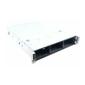
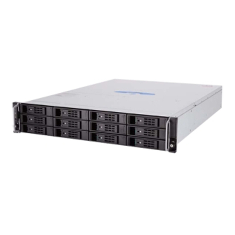
Figure 1. Intel®Storage Server System JBOD2312S3SP.................................................................................................................. 1
Figure 2. Intel®JBOD2000S3 System Family Components ............................................................................................................. 2
Figure 3. 12 x 3.5” Drive JBOD2312S3SP Front View ...................................................................................................................... 2
Figure 4. Front Panel Options............................................................................................................................................................... 3
Figure 5. JBOD2312S3SP Back View................................................................................................................................................... 3
Figure 6. Front view of Front Bezel ...................................................................................................................................................... 4
Figure 7. 12 x 3.5-inch Hard Drive Backplane Components (Front View) ..................................................................................... 4
Figure 8. 12 x 3.5-inch Hard Drive Backplane Components (Rear View) ....................................................................................... 4
Figure 9. 12x3.5” Single-port JBOD 2000S3 Interconnection Diagram ........................................................................................ 5
Figure 10. System Air Flow.................................................................................................................................................................... 6
Figure 11. Removing the Front Bezel .................................................................................................................................................. 7
Figure 12. Installing the Front Bezel.................................................................................................................................................... 7
Figure 13. Installing the Badge to the Front Bezel ............................................................................................................................ 8
Figure 14. Removing the Badge from the Front Bezel...................................................................................................................... 8
Figure 15. Removing the System Cover .............................................................................................................................................. 9
Figure 16. Installing the System Cover................................................................................................................................................ 9
Figure 17. Installing Hard Disk Drive – Removing 3.5” HDD Carrier ............................................................................................. 10
Figure 18. Installing Hard Disk Drive – Removing 3.5” HDD Interface Bracket ........................................................................... 10
Figure 19. Installing Hard Disk Drive – Installing 3.5” HDD............................................................................................................ 10
Figure 20. Installing Hard Disk Drive – Installing 2.5” HDD............................................................................................................ 11
Figure 21. Installing Hard Disk Drive – Inserting 3.5” HDD Assembly .......................................................................................... 11
Figure 22. Removing the Power Supply Module ............................................................................................................................. 12
Figure 23. Removing the Filler Panel................................................................................................................................................. 12
Figure 24. Installing the Power Supply Module ............................................................................................................................... 12
Figure 25. Removing the Riser Assembly.......................................................................................................................................... 13
Figure 26. Removing the SAS Expander............................................................................................................................................ 13
Figure 27. Installing the SAS Expander ............................................................................................................................................. 14
Figure 28. Installing the Riser Assembly ........................................................................................................................................... 14
Figure 29. Removing the Power Distribution Board........................................................................................................................ 15
Figure 30. Installing the Power Distribution Board ......................................................................................................................... 15
Figure 31. Replacing a System Fan .................................................................................................................................................... 16
Figure 32. Removing 3.5” Hard Drive Backplane – Remove the Hard Drive Cage...................................................................... 16
Figure 33. Removing 3.5” Hard Drive Backplane – Remove the Backplane ................................................................................ 17
Figure 34. Installing 3.5” Hard Drive Backplane – Install the Backplane ..................................................................................... 17
Figure 35. Installing 3.5” Hard Drive Backplane – Install the Hard Drive Cage ........................................................................... 17
Figure 36. Installing 3.5” Hard Drive Backplane – Install the Stiffener and Hard Drives........................................................... 18
Figure 37. Installing the Rack Handle ................................................................................................................................................ 18
Figure 38. Removing the Rack Handle............................................................................................................................................... 18
Figure 39. Installing the Interposer Card .......................................................................................................................................... 19
Figure 40. Installing the Storage Front Panel................................................................................................................................... 19
Figure 41. Removing the Storage Front Panel ................................................................................................................................. 19
Figure 42. Removing the Interposer Card......................................................................................................................................... 20
