Intelbras IVA 9100 TRI User manual

User manual
IVA 9100 TRI

IVA 9100 TRI
Multi-beam virtual fence sensor
Congratulations, you have just purchased a product with Intelbras quality and safety.
The IVA 9100 TRI sensor is a product of high performance and advanced technology. Equipped with
high performance lenses, which provide greater efciency against unwanted shots, and can be installed
indoors, semi-open and outdoors.The IVA 9100 TRI has an integrated two-digit display, which provides
greater ease and agility in the alignment procedure, eliminating the need for a multimeter. Read the
product introductory information carefully for the correct use of the sensors.

Care and safety
» Install the sensor in a stable location that is not subject to ickering.
» Install the transmitter and receiver so that they are aligned;
» LGPD - General Law for the Protection of Personal Data: Intelbras does not access, transfer, capture, or perform any other
type of treatment of personal data from this product.
» Do not install the sensor in locations where beam obstruction may occur. Check that there are no plants, branches or
other objects that could obstruct the sensor beam;
» Do not install the receiver and transmitter with the lens facing the sun;
» Make sure that the sealing rubbers are installed in order to prevent the entry of water and insects;
» Size the power supply and power cord correctly;
» Do not leave the cable exposed to the sun, rain or moisture;
» Do not install the sensor above the recommended distance;
» Always check that there are no reections on clear and polished surfaces, which can prevent the sensor from triggering.
Do walking tests in different positions along the barrier to make sure there are no reections;
» To clean the outside of the sensor, use a cloth moistened with water; never use chemicals.
» Avoid installing the receiver near sources of electromagnetic noise. After installation, perform tests to verify the correct
functioning of the product. In case of interference, exchange the Transmitter with the Receiver;
» For installation of stacked sensors, the maximum number of sensors installed is 4 (four) and they must be in different
frequency channels, as shown in the image below. For installation in perimeters, follow the channel arrangement also
shown in the gure below;
X
TX
Channel 1
RX
Channel 1
RX
Channel 3
TX
Channel 3
TX
Channel 2
TX
Channel 4
RX
Channel 4
RX
Channel 2
TX
Channel
1
RX
Channel
1
TX
Channel 1
RX
Channel 3
TX
Channel 3
RX
Channel 1
TX
Channel 4
TX
Channel 2
RX
Channel 4
RX
Channel 2
Perimeter
TX
Channel 1
RX
Channel 1
RX
Channel 3
TX
Channel 3
TX
Channel 2
TX
Channel 4
RX
Channel 4
RX
Channel 2
» In order to avoid interference between sensors on the same channel, respect the side protection distance as specied
below.
TX
Channel 1
TX
Channel 1
RX
Channel 1
RX
Channel 1
Side protection distance
Distance between TX and RX
DPL DPL
TX
RX
» For the IVA 9100 TRI sensor, follow the protection distances below:
Distance between TX and RX
20 m 60 m 100 m 200 M
Side Protection Distance (DPL) > 2.5 m > 7.5 m > 12.5 m > 25 M
Vertical Protection Distance (DPV) Maximum stacking of 4 sensors on different frequency channels
That is, the Side Protection Distance is always the distance between RX and TX divided by 8 (eight).
Distance between TX and RX
8
DPL> [m]
In outdoor environments with a high rate of fog or rain, install the sensors at a maximum of 50%
of the distance specied for each model, in order to avoid false alarms.


6
1. Technical specications
Number of beams 3
Power supply voltage 12 ~ 24 Vdc / Vac
Consumption current (TX + RX) ≤ 100 mA @ 12 Vdc
Frequency channels 4 channels - CH1, CH2, CH3 and CH4
Maximum distance between TX
and RX
Indoor: 200 m
External: 100 m
Alarm output Independent NA / NF terminals, 1 A max
Response time Adjustable: 50 ms, 100 ms, 300 ms and 700 ms
Alarm Time ≥ 2s
Detection method Block all 3 beams simultaneously
Alignment indication LED Alignment and 2-digit display
Trigger indication Trigger LED and 2-digit display
Tamper Independent output, without polarity and normally closed on RX and TX
Heater
function Yes, on RX and TX2
Horizontal Alignment 180° (± 90°)
Vertical Alignment 20° (± 10°)
Solar lter for outdoor environments Yes
Operating temperature -10 ºC to + 55 ºC
IP protection grade IP65
Color Black
Weight 1500 g, approx.
Dimensions (B × W × D) 90.5 × 290.8 × 92 mm
1
Current consumed without updating the heater.
2
The heating element is not included with the product.
2. Product
Front Cover
Screw
Intelbras
Shield
2 digit display Brackets for installation on poles
Base
Cover xing screw nut
Passage
installation
screws
Conguration DIP
Switches
Base
Terminals
Passage of the wire
Tamper
Lentes
Adjust vertical alignment
Latch adjustment
horizontal alignment
Status LEDs

7
3. General characteristics
The IVA 9100 TRI sensor is a 3-beam active infrared sensor designed for the most adverse scenarios. Several features and
functionality have been added to the sensor to provide robustness, the main ones being described below:
» High quality optical assembly;
» Visualization of the alignment level by display: in order to facilitate the alignment of the sensors, the product has a 2-digit
display that indicates the alignment level. It is always recommended to align the sensors with the level of 99, reducing
the possibility of unwanted shots;
» Heating output for connection with a resistor in order to avoid dew and/or dirt in the sensor cabinet.There are two modes
of operation of the heater:
» Intelligent: the heating resistor is activated when the temperature drops below +5 ° C and turned off when the temperature exceeds
+10 ° C;
» On: keeps the heating element always on. This mode is recommended only for testing the functioning of the resistor.
The heating resistance is a high power resistor that has the purpose of generating heat in order to
avoid the accumulation of dew and / or dirt on the outside of the cabinet, which is widely used in
barrier sensors. It must follow the following specications:
Product supply voltage: 12 Vdc / Vac Product supply voltage: 24 Vdc / Vac
3 W power 5W power
Maximum current 200 mA Maximum current 200 mA
Recommended resistance from 68Ω / 3 W to 120 Ω / 3 W Recommended resistance from 120Ω / 5 W to 300Ω / 5 W
Whenever the heating resistor is used, function tests must be carried out in the On mode to check the behavior of the
resistor. After testing, it is recommended to keep the Heater in Intelligent operating mode. This function is recommended
only for regions of extreme cold.
Make sure that the amperage of the power supply is sufcient to supply current to the heater.
» Energy saving mode, which turns off the display and the LEDs of the receiver after 30 min without the infrared barrier
being interrupted;
» Response time adjustable from 50 to 700 ms;
» 4 Frequency channels
» Intelbras shield.

8
Below are the congurations of the Receiver and Transmitter.
Receiver Settings
Frequency channels Keys 1 and 2
CH1 - Frequency channel 1
CH2 - Frequency channel 2
CH3 - Frequency channel 3
CH4 - Frequency channel 4
Heater key 3
Intelligent - turns the heater on below + 5 ° C
and turns it off above + 10 ° C
On - the heater is constantly on
Response time Keys 4 and 5
50 ms
100 ms
300 ms
700 ms
Transmitter Settings
Frequency channels Keys 1 and 2
CH1 - Frequency channel 1
CH2 - Frequency channel 2
CH3 - Frequency channel 3
CH4 - Frequency channel 4
Heater key 3
Intelligent - turns the heater on below + 5 ° C
and turns it off above + 10 ° C
On - the heater is constantly on
4. Installation
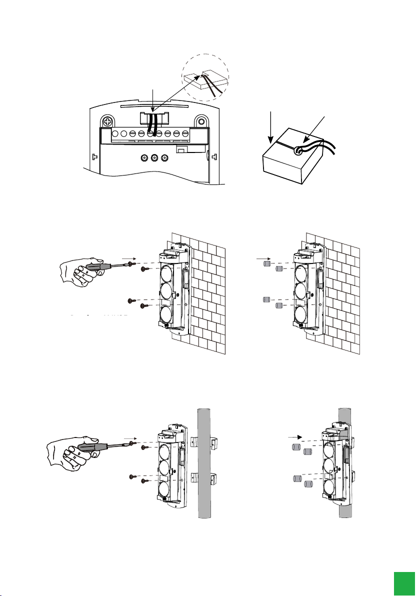
1. To identify the Transmitter and Receiver, simply check the label located on the back of the product. Below, the step by
step to open the sensor cabinet and perform the installation:
IVA 9100 TRI - RECEPTOR
Remova o
parafuso
Etiqueta de
Identificação
Remova a tampa frontal
conforme movimento
indicado na figura
Identica-
tion Tag
Remove the screw
Remove the front cover as
shown in the gure
9
2. After identication, run the cable as shown in the following image to connect it to the terminal block: Use the sealing
rubber to prevent insects from entering the sensor:
Passagem
de cabo
Borracha de
vedação Cabo
passage of the cable
Sealing Rubber
Cable
3. Attach the sensors in the installation position and then use the screw sealing rubbers, following the recommendations
below:
a) Wall installation
Parafuso M4X25mm Borracha de
vedação
1ª 2ª
Screw M4 × 25 mm
2nd1st
Sealing Rubber
b) Pole installation
Note:
it is recommended to use a pole with a diameter of Ø38 ~ Ø50 mm.
Parafuso M4x30mm
Borracha de
vedação
1ª 2ª
Screw M4 × 30 mm
1st 2nd
Sealing Rubber

10
4. Connect the wires to the terminals following the guidelines below.
» Connect the power to the receiver and transmitter board (12 ~ 24 Vdc / Vac - no polarity);
» Connect the wires from the sensor’s alarm output to the zone input of your control panel;
» Both the Receiver and the Transmitter have a normally closed and tamper independent output. If desired, connect the wires from the tamper output to the
zone input of your control panel.
12~24
VAC/DC TAMPER AQUECEDOR 12~24
VAC/DC CM NF NA TAMPER AQUECEDOR
FONTE
GND +12V
Connect the
control panel Connect the control panel
Transmissor Receptor
Transmitter Receiver
5. Both the Receiver and the Transmitter have an independent Heater output, which is recommended for extremely cold
areas. If desired, connect the heater output wires to a resistor.
key 3 Intelligent - turns the heater on below + 5 ° C and turns it off above + 10 ° C
On - the heater is constantly on
12~24
VAC/DC TAMPER AQUECEDOR 12~24
VAC/DC CM NF NA TAMPER AQUECEDOR
Transmissor Receptor
Resistance Resistance
Transmitter Receiver
6. Congure the frequency channel using the keys (Keys 1 and 2) Frequency channels. For the sensor to function correctly, the
transmitter (TX) and receiver (RX) must be on the same frequency channel:The factory default is frequency channel 1 (CH1).
123
ON 123
ON 45
Transmissor
12
Canais de Frequência
CH1
CH2
CH3
CH4
12
Canais de Frequência
CH1
CH2
CH3
CH4
Receptor
Transmitter Receiver
Frequency channels
Frequency channels
7. Congure the response time using the keys (Keys 4 and 5) Response time. This setting determines the time that the bea-
ms must be blocked to trigger the sensor, being congured only at the receiver. The table below associates the response
time with the interruption speed of the beams to assist in choosing the response time. The factory default is 50 ms.
123
ON 45
Receptor
45
Tempo de Resposta
50MS
100MS
300MS
700MS
45
Receiver
Response time
Response time Detection Speed
50 ms Intense running
100 ms Moderate running
300 ms Light running
700 ms Walking
11
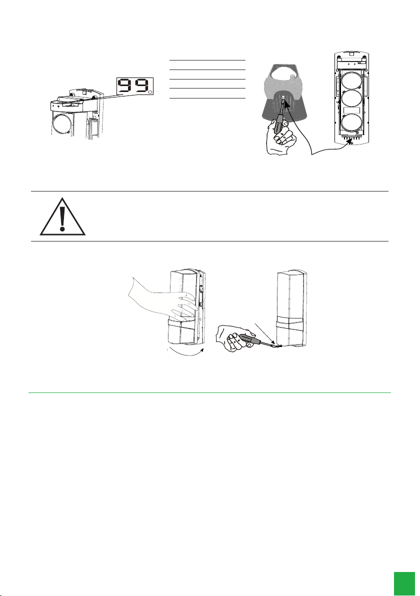
8. Align the sensors. The quality of the sensor alignment is identied by the 2-digit display located on the Receiver according
to the table below. After aligning, tighten the horizontal adjustment screw.
Trava ajuste alinhamento
horizontal
Signal level
95 ~ 99 Great
90 - 94 Good
80-89 Poor
01 ~ 79 Very Poor
Lock adjustment horizon-
tal alignment
It is recommended that when aligning the sensors, the level observed on the display is 99.
Perform walking tests at various points on the barrier to make sure that there is no reection from
the infrared beams on the oor, wall or reective objects. If reection is found, it will be necessary to
change the installation position of the sensor.
9. After completing the conguration, t the top of the cover to the base and tighten the cover xing screw on the trans-
mitter and receiver, as shown in the gure below:
Aperte o
parafuso
Coloque a tampa
frontal conforme
indicado na figura
Tighten
the screw.
Place the front
cover as shown in
the gure
5. Troubleshooting
Follow the steps outlined below to troubleshoot your sensor:
1. Check that the installation distance is within the specied. In environments with a high rate of rain or fog, it is recom-
mended that the installation distance be 50% of the maximum distance for outdoor environments;
2. Check the installation wiring and that the supply voltage in the TX and RX is between 12 and 24 Vdc / Vac;
3. Check that both TX and RX are on the same frequency channel, which is selected using the frequency channel switches;
4. Check that the Response Time setting, which is selected using the Response Time switches from 50 ms to 700 ms, is in
accordance with the speed expected to cross the infrared beam;
5. If the heater is being used, change it to
On
using the heater conguration switch and check again that the supply voltage
on the TX and RX is between 12 and 24 Vdc / Vac to make sure that the power supply supports the amperage heating
resistance. After this test, return the heater conguration to its initial state;
6. Redo the alignment procedure;
7. Perform the detection test and conrm that there are no reections.
8. Your infrared barrier sensor will be working!

12
Warranty term
It is established that this warranty is granted upon the following conditions:
Client’s name:
Client’s signature:
Invoice number:
Date of purchase:
Model: Serial number:
Retailer:
1. All the parts, pieces and components of the product are guaranteed against possible manufacturing defects, which may
arise, for the term of 1 (one) year - this being 90 (ninety) days of legal warranty and 9 (nine) months’ contractual war-
ranty –, counting from the date of purchase of the product by the Consumer, as appears in the product purchase bill of
sale, which is an integral part of this Term throughout the domestic territory. This contractual warranty includes the free
exchange of parts, pieces and components which have a manufacturing defect, including the expenses with labor used in
this repair. If there is no manufacturing defect, but defect(s) arising from misuse, the Consumer shall bear these expenses.
2. The installation of the product shall be executed in accordance with the Product Manual and/or Installation Guide. If your
product requires the installation and conguration by a qualied technician, seek a suitable specialized professional, the
costs of these services not being included in the product amount.
3. Having perceived the defect, the Consumer shall immediately contact the nearest Authorized Service which appears in
the report offered by the manufacturer – they are the only ones authorized to examine and remedy the defect during the
warranty term foreseen herein. If this is not respected, this warranty shall lose its validity, as it shall be characterized as
product infringement.
4. If the Consumer requests home service, it shall contact the nearest Authorized Service to inquire about the technical visit
rate. If it is necessary to remove the product, the ensuing expenses, such as those of transportation and insurance of the
taking and return of the product, shall be the Consumer’s responsibility.
5. The warranty shall lose its validity totally in the occurrence of any of the following cases: a) if the defect is not one of manu-
facture, but is caused by the Consumer or by third parties foreign to the manufacturer; b) if the damage to the product arises
from accidents, disasters, agents of nature (lightning, oods, landslides, etc.), humidity, voltage in the electrical network
(excess voltage caused by accidents or excessive uctuations in the network), installation/use in disagreement with the
user’s manual or arising from natural wear of the parts, pieces and components; c) if the product has undergone effects of a
chemical, electromagnetic, electrical or animal (insects, etc.) nature; d) if the serial number of the product has been falsied
or erased; e) if the appliance has been infringed.
6. This warranty does not cover loss of data; therefore, it is advisable that if it is the case of the product, the Consumer makes
a backup regularly of the data which appears in the product.
7. Intelbras is not responsible for the installation of this product, or for possible attempts at fraud and/or sabotage in its
products. Maintain the updates of the software and applications used up-to-date, if it is the case, as well as the network
protection required for defense against hackers. The equipment is guaranteed against defects in its usual conditions of use,
it being important to bear in mind that, as it is electronic equipment, it Is not free of fraud and scams which may interfere
with its correct functioning.
8. After its useful life, the product must be delivered to an authorized Intelbras service center or directly disposed of in an
environmentally appropriate manner to avoid environmental and health impacts. If you prefer, the battery, as well as other
unused Intelbras brand electronics, can be disposed of at any Green Eletron collection point (waste management facility
to which we are associated). If you have any questions about the reverse logistics process, please contact us at (48) 2106-
0006 or 0800 704 2767 (Monday to Friday 8am to 8pm and Saturdays 8am to 6pm) or via -mail [email protected].
These being the conditions of this complementary Warranty Term, Intelbras S/A reserves the right to alter the general,
technical and esthetic features of its products without prior notice.
The manufacturing process of this product is not covered by the requirements of ISO 14001.
All the images of this manual are illustrative.

01.21
Made in China
Customer Support: (48) 2106 0006
Forum: forum.intelbras.com.br
Support via chat: intelbras.com.br/suporte-tecnico
Support via e-mail: suporte@intelbras.com.br
Customer Service: 0800 7042767
Where to buy? Who installs it? 0800 7245115
Imported to Brazil by: Intelbras S/A – Indústria de Telecomunicação Eletrônica Brasileira
Rodovia SC 281, km 4,5 – Sertão do Maruim – São José/SC – 88122-001
CNPJ 82.901.000/0014-41 – www.intelbras.com.br
Table of contents


