Intellijel Quadratt 1U User manual

Quadratt 1U Manual
Quadratt 1U
Quad attenuator, attenuverter, mixer and DC voltage source
Manual Revision: 2017.10.03

Quadratt 1U Manual
Table of Contents
Table of Contents
Overview
Usage Examples
Installation
Before Your Start
Installing Your Module
Front Panel
Controls
Inputs & Outputs
Technical Specifications
Page 1

Quadratt 1U Manual
Overview
Quadratt is a four channel active/buffered attenuverter and summing mixer. Each channel has
a knob, which can function as a unipolar attenuator or a bipolar attenuverter, depending on the
setting of its corresponding two-position switch.
Each input is normalled to a precision +5V DC voltage source. With nothing plugged into the
jacks, each knob controls a voltage range of 0 to +5 v or -5 to +5 v depending on the position of
the mode switch.
Each output is normalled to mix into the channel to its right making it possible to do sub mixes in
groups of 2, 3 or all four channels.
Usage Examples
This humble collection of simple parameters provides a wealth of useful functions to the
modular synthesist. Here are some basic examples of how you might employ Quadratt in your
patches:
●Attenuation: Assume you want to subtly
modulate filter resonance, but your filter of
choice doesn’t have a built-in attenuator on its resonance CV input. If you plug the
output of your LFO directly into the resonance CV input on your filter, you’ll be
modulating it at full amplitude — meaning your LFO will be cycling the resonance
between “none” to “ear shattering squelch” and back again. But what if you just want
resonance to undulate a little bit? Quadratt to the rescue!
Plug the output of your LFO into one channel of the Quadratt, then plug the output of
that channel into your filter’s resonance jack. You’ll now be able to “dial down” the
peak-to-peak amplitude of the LFO using the Quadratt’s corresponding attenuator knob.
●Inversion: Assume you want to control a module with an envelope. Normally, voltage
increases during the attack section of an ADSR, then decreases during the decay or
release segment. But what if you want the inverse? What if you want some sonic
attribute to get more
pronounced as the signal decays, not less? For this you need to
invert the envelope. Once again, Quadratt to the rescue!
Plug the output of your envelope into one channel of the Quadratt, set that channel’s
polarity switch to +/-, then turn the corresponding attenuator knob counterclockwise past
12:00 — an inverted envelope now appears at Quadratt’s corresponding output.
●Voltage Offsets: Assume you have a Sample & Hold module sending random notes to
an oscillator, only you want to constrain that unruly 10+ octave range of notes to just one
or two octaves in the bass. One way to do this is to use two channels of a Quadratt.
Page 2

Quadratt 1U Manual
Plug your S&H output into Quadratt’s Channel B and the output of Channel B into your
oscillator, then use the Channel B attenuator to limit the range of notes to an octave or
two. Next, use Quadratt’s Channel A (into which nothing is connected) to negatively
offset the note range down into the bass frequencies. Do this by setting Channel A’s
polarity switch to +/-, then turning the corresponding attenuator knob counterclockwise
past 12:00. Because nothing is plugged into Quadratt Output A, Output B contains a
sum of Channels A and B, giving you both the reduced note range and the low
frequencies you desire.
●CV Mixing: What if you want to modulate some parameter with more than one control
voltage at a time? Perhaps you want to send a square wave to modulate a filter’s cutoff
frequency giving it a steady “pulsing” sound while simultaneously sweeping it with a
slow, triangular LFO so that the pulsing sound rises and falls over time. Again, Quadratt
is on the case. And, once again, you’ll be using two channels.
Plug the square wave output of the “pulsing” LFO into Quadratt’s Channel A and the
output of Quadratt’s Channel B into your filter’s frequency CV input. Use Channel A’s
attenuverter to set the amount of pulse you want to hear. Next plug the triangle wave
output of the “slow sweeping” LFO into Quadratt’s Channel B. The output of Channel B
is already connect to your filter frequency and it contains of sum of Quadratt’s A and B
channels. Use Channel B’s attenuverter to set how much the pulse sweeps up and down
the frequency band. You now have two different CV sources controlling one destination.
Want more? Quadratt does have 2 more channels available...
●Audio Mixing: Audio is a voltage too. So you’re probably asking yourself, “can I use
Quadratt to mix multiple channels of audio
together as well?” Yes, you can!
Set all of Quadratt’s polarity switches to UNI and turn all its knobs fully counterclockwise.
Plug the output of one oscillator in Channel A, another into Channel B, and so on. Plug
only Output D into your audio amplifier. Slowly rotate Channel A’s attenuator clockwise
and you’ll hear the oscillator connected to Channel A. Slowly turn Channel B’s attenuator
clockwise, and you’ll hear a mix of the two oscillators. Use Channel C and Channel D’s
attenuators to add their corresponding oscillators to the mix.
Page 3

Quadratt 1U Manual
Installation
Intellijel Eurorack modules are designed to be used with a Eurorack-compatible case and power
supply.
Before Your Start
Before installing a new module in your case you must ensure your case’s power supply has
sufficient available capacity to power the module:
● Sum up the specified +12V current draw for all modules, including the new one. Do the
same for the -12 V and +5V current draw. The current draw will be specified in the
manufacturer's technical specifications for each module.
● Compare each of the sums to specifications for your case’s power supply.
● Only proceed with installation if none of the values exceeds the power supply’s
specifications. Otherwise you must remove modules to free up capacity or upgrade your
power supply.
You will also need to ensure you have enough free space (hp) as well as free power headers in
your case to fit the new module.
You can use a tool like ModularGrid to assist in your planning. Failure to adequately power your
modules may result in damage to your modules or power supply. If you are unsure, please
contact us before proceeding.
Installing Your Module
When installing or removing a module from your case always turn off the power to the case and
disconnect the power cable. Failure to do so may result in serious injury or equipment damage.
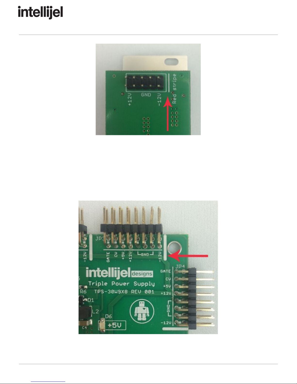
Ensure the 10-pin connector on the power cable is connected correctly to the module before
proceeding. The red stripe on the cable must line up with the -12V pins on the module’s power
connector. The pins are indicated with the label -12V, a white stripe next to the connector, the
words “red stripe”, or some combination of those indicators.
Page 4
Quadratt 1U Manual
Most modules will come with the cable already connected but it is good to double check the
orientation. Be aware that some modules may have headers that serve other purposes so
ensure the cable is connected to the right one.
The other end of the cable, with a 16-pin connector, connects to the power bus board of your
Eurorack case. Ensure the red stripe on the cable lines up with the -12V pins on the bus board.
On Intellijel power supplies the pins are labelled with the label “-12V” and a thick white stripe:
Page 5

Quadratt 1U Manual
If you are using another manufacturer’s power supply, check their documentation for
instructions.
Once connected, the cabling between a module and power supply should resemble the picture
below:
Before reconnecting power and turning on your modular system, double check that the ribbon
cable is fully seated on both ends and that all the pins are correctly aligned. If the pins are
misaligned in any direction or the ribbon is backwards you can cause damage to your module,
power supply, or other modules.
After you have confirmed all the connections, you can reconnect the power cable and turn on
your modular system. You should immediately check that all your modules have powered on
and are functioning correctly. If you notice any anomalies, turn your system off right away and
check your cabling again for mistakes.
Page 6

Quadratt 1U Manual
Front Panel
Controls
1. Channel A attenuator
Sets the amount of attenuation for the IN A input. The behaviour of the knob depends on
the position of the corresponding polarity switch. The attenuation amount is linear.
2. Channel A polarity switch
This is a 2-position switch that sets the polarity of the OUT A signal.
With the switch in the left UNI position the channel functions as a standard attenuator.
OUT A outputs the unmodified signal from IN A when the attenuator knob is fully
clockwise, and it outputs no signal (0 V) when the knob is fully counterclockwise.
With the switch in the right +/- position the channel acts a bipolar attenuverter. The
output is the unmodified input with the knob fully clockwise, the inverse of the input with
the knob fully counterclockwise, and 0 V when the knob is at the 12 o’clock position.
3. Channel B attenuator
Behaves the same as the Channel A attenuator but for channel B.
4. Channel B polarity switch
Behaves the same as the Channel A polarity switch but for channel B.
Page 7

Quadratt 1U Manual
5. Channel C attenuator
Behaves the same as the Channel A attenuator but for channel C.
6. Channel C polarity switch
Behaves the same as the Channel A polarity switch but for channel C.
7. Channel D attenuator
Behaves the same as the Channel A attenuator but for channel D.
8. Channel D polarity switch
Behaves the same as the Channel A polarity switch but for channel D.
Inputs & Outputs
A. IN A
Input for channel A.
With no cable plugged in, Quadratt sends a 5V DC voltage into Channel A, which you
can attenuate (or invert) with the Channel A attenuator knob. For example, with nothing
plugged into Channel A and the Channel A knob fully clockwise, 5V is sent out channel
A. If the Channel A knob is fully counterclockwise and its polarity switch is set to UNI,
then 0V is sent out Channel A. if the Channel A knob is fully counterclockwise and its
polarity switch is set to +/-, then -5V is sent out Channel A.
B. IN B
Input for channel B. With no cable plugged in, Quadratt sends 5V into Channel B, which
you can attenuate (or invert) with the Channel B attenuator knob.
C. IN C
Input for channel C. With no cable plugged in, Quadratt sends 5V into Channel C, which
you can attenuate (or invert) with the Channel C attenuator knob.
D. IN D
Input for channel D. With no cable plugged in, Quadratt sends 5V into Channel D, which
you can attenuate (or invert) with the Channel D attenuator knob.
E. OUT A
Output for channel A, which is the attenuverted value of IN A.
F. OUT B
Output for channel B, which is the attenuverted value of IN B. With no cable connected
to OUT A, this jack outputs the sum of channels A and B.
Page 8

Quadratt 1U Manual
G. OUT C
Output for channel C, which is the attenuverted value of IN C. With no cable connected
to OUT A or OUT B, this jack outputs the sum of channels A, B and C. Plugging a cable
into OUT A removes it from OUT C, meaning OUT C = OUT B + OUT C. Plugging a
cable into OUT B removes both OUT A and OUT B from OUT C.
H. OUT D
Output for channel D, which is the attenuverted value of IN D. With no cable connected
to OUTS A, B or C, this jack outputs the sum of channels A through D. Plugging a cable
into OUT A removes it from OUT D, meaning OUT D = OUTS B + C + D. Plugging a
cable into OUT B removes both OUT A and OUT B from OUT D, meaning OUT D =
OUT C + D. Plugging a cable into OUT C removes OUTS A through C from OUT D.
Page 9

Quadratt 1U Manual
Technical Specifications
Width
28 hp
Maximum Depth
25 mm
Current Draw
24 mA @ +12V
23 mA @ -12V
Page 10
Other manuals for Quadratt 1U
4
Table of contents
Other Intellijel Mixer manuals


