Assembly Instructions | Montageanleitung l 3
Hinweis: Haben Sie diesen Schrank als montierte Variante gekauft, prüfen Sie, ob alle Elemente fest
verschraubt sind, bevor Sie ihn in Betrieb nehmen und Netzwerkkomponenten einbauen.
Einleitung
•Diese Anleitung ist anwendbar für alle Intellinet Server- und Netzwerkschränke der Basic Line
•Einige Abbildungen können vom tatsächlichen Produkt abweichen
•Führen Sie alle Montageschritte aus dieser Anleitung vollständig aus
•Wenn Sie im Lieferumfang Teile finden, die nicht in dieser Anleitung erwähnt werden,
verwenden Sie das separate Blatt „Special Instructions“, das diesem Schrank beiliegt.
•Je nach Modell liegen diesem Schrank unterschiedliche Teile bei, z. B. eine perforierte
Tür oder eine Glastür
•Bitte lesen Sie diese Anleitung vollständig, bevor Sie mit der Montage beginnen
Benötigtes Werkzeug:
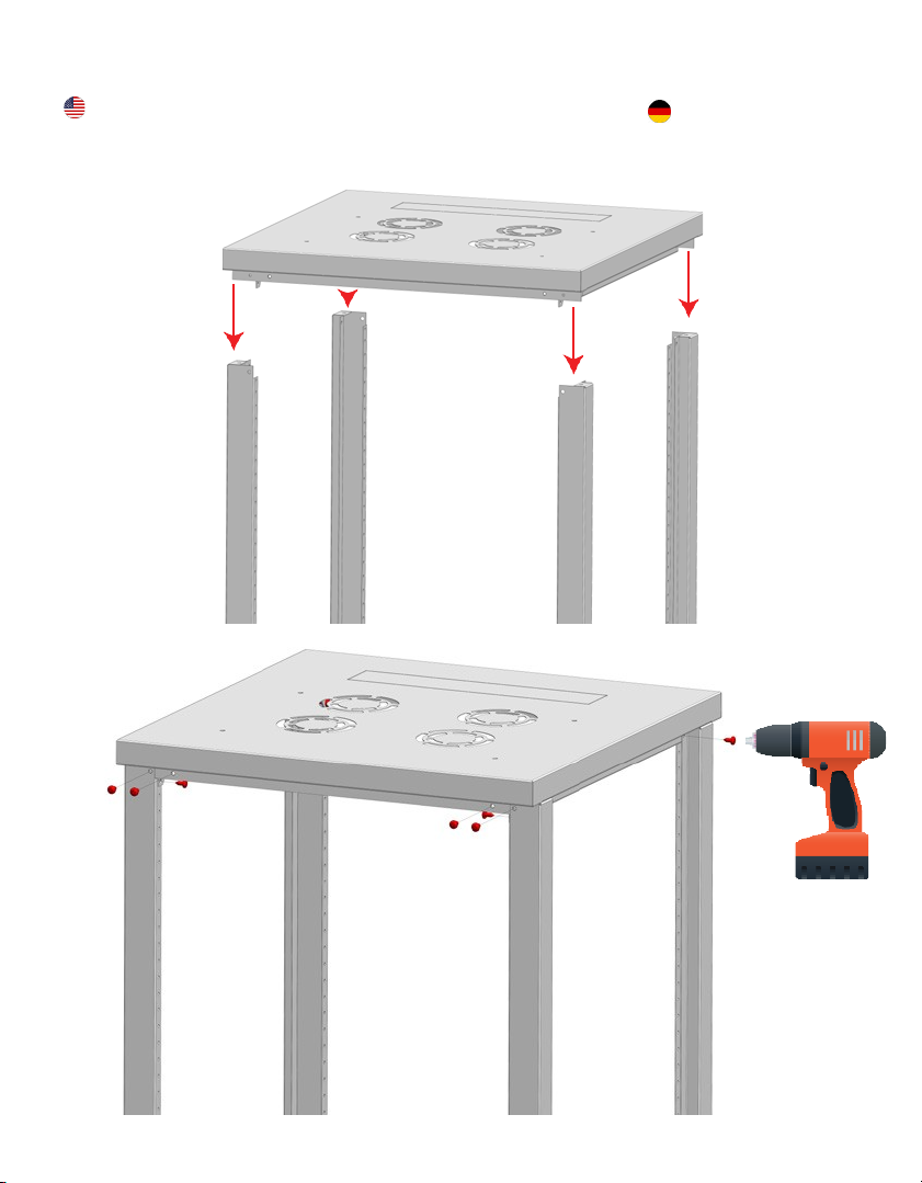
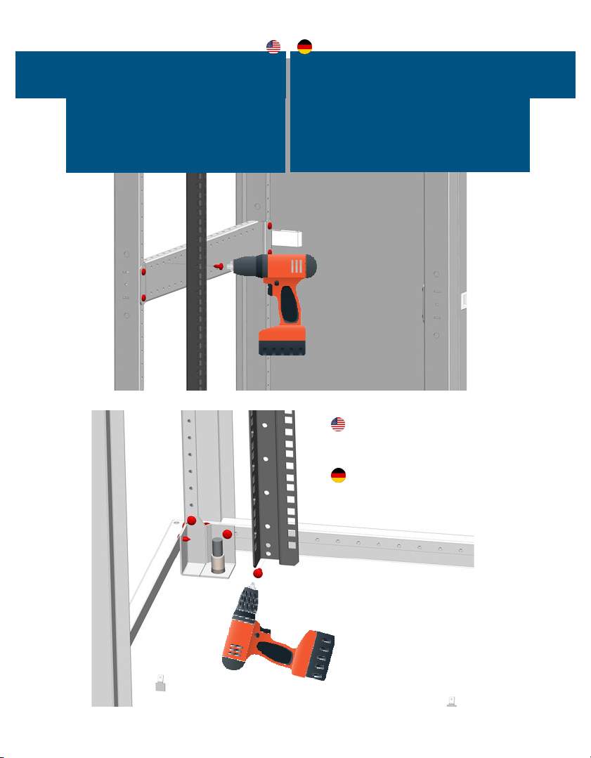
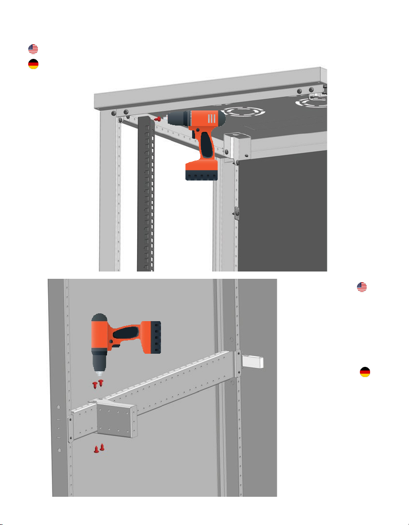
M5 X12 Sechskantschrauben 68 68 24 40
M12 X85 Nivellierfüße 4444
Rahmen für Unterseite 1111
Dach 1111
Vertikale Tragschienen 2244
Horizontale Tragschienen 2222
Tragwinkel für Seiten 0204
19"-Montageschienen 2244
Seitenwände 2222
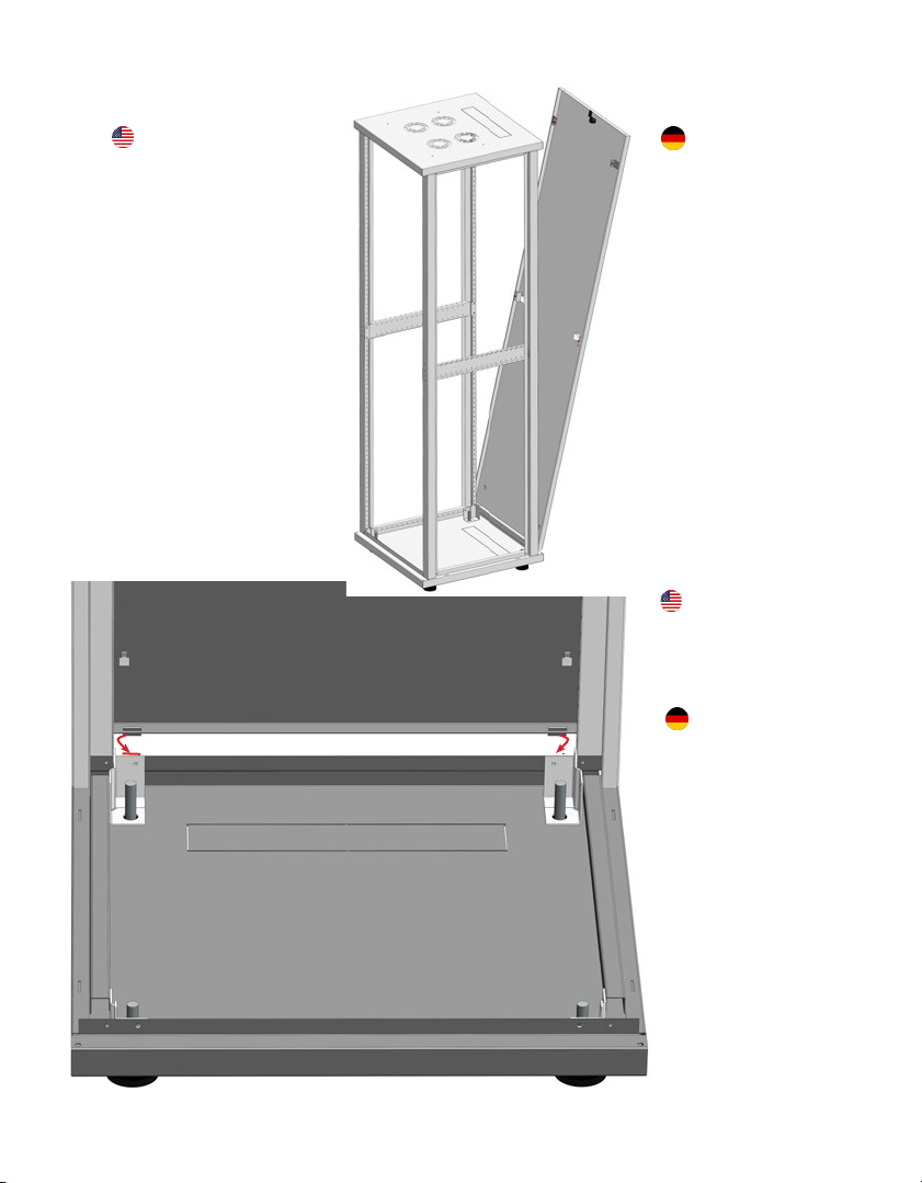
Rückwand 1100
Fronttür 1100
Perforierte Tür, Front- & Rückseite 0022
Verriegelungsplatte für Rückwand 2200
Halterungswinkel für Tür/Rückwand 2200
Fixierungshaken für Palette 4444
Netzwerkschränke
(26HE-47U)
Sechskantschrauben