intensity ICHS-120KC-5 Operating instructions

AIR COOLED
MODULAR CHILLER
MAN-I-IOCH10-0715
intensity.mx
INSTALLATION &
OWNER´S MANUAL
ICHS-120KC-5 - 10 TONS.

NO.
NAME
Top cover Air outlet Air inlet Water inlet Electric
control box
Water outlet
MAIN PARTS OF THE UNIT
NO
.
NAME
Top cover Air outlet Air inlet
Air outlet
W
a
t
e
r inl
et
El
ec
tr
ic
co
ntr
o
l
box
Wa
t
e
r
ou
tl
et
M
AIN
PART
S
O
F
THE
U
NIT

OPERATION & PERFORMANCE
a. The standard voltage of power supply is 220V 3N~60Hz, the minimum allowable voltage is 198V, and the maximum voltage is 242V.
b. To maintain better performance, please operate the unit under the following outdoor temperature:
Operating range under cooling mode Operating range under heating mode
10°C~52°C -10°C~21°C
c. The unit is of outlet water temperature control mode
outlet water temperature control—cooling: minimum temperature 5°C, maximum temperature 17°C; heating: minimum tempera-
ture 45°C, maximum temperature 50 °C.
If low-temperature water outlet unit is required, it should specially be customized.
If the user requires the unit to operate under the outlet water temperature is lower than
the minimum setting value mentioned above, be sure to make the requirement to the dealer or
our maintenance center, and necessary protective measures should be taken before the unit
is used.
Performance characteristics of the unit
Use conditions of the unit
The air-cooled heat pump modular unit is composed of one or more modules. Each module has its own independent electric
control unit, and the electric control units of modules conduct information exchange through communication network. The
air-cooled heat pump modular unit is characteristics of compact structure and easy transportation and lifting, and in the meanwhile,
it also saves facilities, including cooling tower, cooling pump, and so on, for the user, and reduces installation cost.
The units provide central air handling devices or terminal equipment with chilled water or hot water. The unit is a completely
independent entirety type one, which is designed to be installed outdoors (on the ground or the roof). Each unit includes such main
parts as high-efficient and low-noise scroll compressor, air-cooled condenser, shell and tube (or plate) evaporator, micro-computer
control center, and so on. These parts are installed on steel structure base, so they are sound and durable.
The unit applies Chinese micro-computer control system, which can automatically conduct energy control according to the
magnitude of load, to achieve optimal matching and thus actually realizing optimal energy-saving operation. The product is
modularized unit, and parallel connection of 16 modules can be realized at most, so the user can adopt module combination
according his own demands. The product can be widely applied in air-conditioning engineering of various newly-built and rebuilt
industrial and civil buildings, such as restaurant, hotel, apartment, office building, hospital, industrial plant, and so on. The
air-cooled heat pump modular unit is the best choice for the place which has high requirement in noise and ambient environment
and which is short of water.
O
PERATI
O
N
&
PERF
O
RMAN
CE
a.
The
e
e
e
e
e
e
e
e
st
s
s
s
s
s
s
andard
vo
vo
vo
vo
vo
v
v
v
v
lta
lta
lta
lta
lta
ta
a
a
ge
g
g
ge
ge
ge
ge
ge
ge
of power supply is 220V 3N~60Hz, the minimum allowable voltage is 198V, and the maximum voltage is 242V
.
V
V
b.
To
To
To
To
To
T
To
To
To
o
mai
mai
mai
mai
mai
mai
mai
ma
m
nta
ta
nta
nta
nta
a
nta
nta
nta
nt
i
i
in
i
i
i
i
i
bet
be
be
bet
bet
be
bet
bet
e
ter
ter
ter
er
er
ter
er
e
e
e
pe
pe
pe
p
p
p
p
rfo
rfo
rfo
rfo
fo
rfo
rfo
rfo
rfo
r
rma
nce
e
e
e
, p
, p
, p
lea
se
s
se
s
se
ope
o
o
o
o
o
rat
t
t
t
e t
et
t
et
t
t
e t
t
he
uni
uni
uni
uni
tu
tu
tu
t u
nde
nde
nde
nde
r t
r
r
r
r
r
he
e
e
e
e
fol
fol
fol
fol
low
low
low
low
ing
in
n
in
in
ou
u
u
u
u
u
tdo
td
d
td
d
td
d
d
or
tem
e
em
em
em
per
p
p
p
atu
u
u
u
u
u
u
u
u
re:
re
re
re:
re:
re:
Op
Op
Op
Op
Op
Op
O
Op
Op
Op
er
e
e
e
e
e
e
e
t
at
t
at
at
at
at
i
i
in
i
i
i
g range under cooling mode Operating range under heating mode
10
°
C
~5
2
°C
-1
1
1
11
1
1
1
0
0
0
0
0
0
0
0
°
°
°
°
C
C~
21
1
1
1
1
1
1
1
°C
°C
°C
°C
°C
C
C
°C
°C
c. The unit is o
f
outlet water te
mpe
rature control mode
out
l
et water temperature contro
l
—coo
li
n
g
: m
i
n
i
mum temperature
5
°C
,
maximum temperature
1
7
°C
;
h
eat
i
n
g
: m
i
n
i
mum tempera
-
tur
e 4
5
°C
, maximum tem
p
erature 5
0
°C
.
If low-temperature water outlet unit is required, it should specia
lly
be customized.
If the user re
qu
ires the unit to o
pe
rate under the outlet water te
mp
erature is lower than
t
he minimum settin
g
value mentioned above, be sure to make the requirement to the dealer or
our maintenance center, and necessary protective measures should be taken be
f
ore the unit
i
s
used
.
P
e
r
fo
rm
a
n
ce
c
h
a
r
acte
ri
st
i
cs
of
t
h
e
u
ni
t
Use
co
n
d
i
t
i
o
n
s
o
f
t
h
e
u
ni
t
The air-cooled heat
p
um
p
modular unit is com
p
osed o
f
one or more modules. Each module has its own inde
p
endent electric
c
ontrol unit, and the electric control units o
f
modules conduct in
f
ormation exchan
g
e throu
g
h communication network. The
a
ir-cooled heat pump modular unit is characteristics of compact structure and eas
y
transportation and liftin
g
, and in the mean
w
hil
e
,
i
t also saves
f
acilities, includi
ng
coolin
g t
ower, coolin
g p
ump, and so on,
f
or the user, and reduces installation cost.
Th
e un
i
ts prov
id
e centra
l
a
i
r
h
an
dli
n
g
d
ev
i
ces or term
i
na
l
equ
i
pment w
i
t
h
c
hill
e
d
water or
h
ot water.
Th
e un
i
t
i
s a comp
l
ete
ly
i
ndependent entiret
y
t
y
pe one, which is desi
g
ned to be installed outdoors
(
on the
g
round or the roo
f)
. Each unit includes such
mai
n
par
ts as
hig
h-e
ff
icient and low-noise scroll com
pre
ssor, air-cooled condenser, shell and tube
(o
r p
lat
e)
eva
por
ator, micro-com
p
u
ter
contro
l
center, an
d
so on.
Th
ese parts are
i
nsta
ll
e
d
on stee
l
structure
b
ase, so t
h
e
y
are soun
d
an
d
d
ura
bl
e.
The unit applies
C
hinese micro-computer control s
y
stem, which can automaticall
y
conduct ener
gy
control accordin
g
to the
mag
nitude o
f
load, to achieve
opt
imal matchin
g a
nd thus actuall
y r
ealizi
ng
opt
imal ener
gy-
sav
ing
op
eration. The
pr
oduct is
modularized unit, and parallel connection o
f
16 modules can be realized at most, so the user can adopt module combination
accordin
g
his own demands. The product can be widel
y
applied in air-conditionin
g
en
g
ineerin
g
o
f
various newl
y
-built and rebuilt
industrial and civil buildi
ngs
, s
uch as restaura
nt,
hotel
, a
par
tme
nt,
o
ff
ice buildin
g,
hos
pit
al,
industrial
pla
nt,
and so on. T
h
e
air-cooled heat pump modular unit is the best choice for the place which has hi
g
h requirement in noise and ambient environment
a
n
d
whi
c
h i
s
s
h
o
rt
o
f w
a
t
e
r.

1
installation & owner’s manual
1. PRECAUTIONS
To prevent injury to the user or other people and property
damage, the following instructions must be followed. Incorrect
operation due to ignoring of instructions may cause harm or
damage.
Ask your dealer for installation of the air conditioner.
Incomplete installation performed by yourself may result in a
water leakage, electric shock, and fire.
Ask your dealer for improvement, repair, and maintenance.
Incomplete improvement, repair, and maintenance may
result in a water leakage, electric shock, and fire.
In order to avoid electric shock, fire or injury, or if you detect
any abnormality such as smell of fire, turn off the power
supply and call your dealer for instructions.
Never replace a fuse with that of wrong rated current or
other wires when a fuse blows out.
Use of wire or copper wire may cause the unit to break down
or cause a fire.
Do not insert fingers, rods or other objects into the air inlet or
outlet.
When the fan is rotating at high speed, it will cause injury.
Never use a flammable spray such as hair spray, lacqueror
paint near the unit.
It may cause a fire.
CAUTION
Do not use the air conditioner for other purposes.
In order to avoid any quality deterioration, do not use the unit
for cooling precision instruments, food, plants, animals or
works of art.
Before cleaning, be sure to stop the operation, turn the
breaker off or pull out the supply cord.
Otherwise, an electric shock and injury may result.
In order to avoid electric shock or fire, make sure that an
earth leak detector is installed.
Be sure the air conditioner is grounded.
In order to avoid electric shock, make sure that the unit is
grounded and that the earth wire is not connected to gas or
water pipe, lightning conductor or telephone earth wire.
In order to avoid injury, do not remove the fan guard of the
outdoor unit.
Do not operate the air conditioner with a wet hand.
An electric shock may happen.
Do not touch the heat exchanger fins.
These fins are sharp and could result in cutting injuries.
Never inspect or service the unit by yourself.
Ask a qualified service person to perform this work.
Do not dispose this product as unsorted municipal
waste.Collection of such waste separately for special treatment
is necessary.
Keep far away from high-frequency equipment.
Keep away from the following places:
a place where it is full of oil gas; places where salty air
surrounding(near the coast); a place where is caustic gas(the
sulfide in hotspring). Location in the folling places may cause
malfunction or shorten the life span of the manchine.
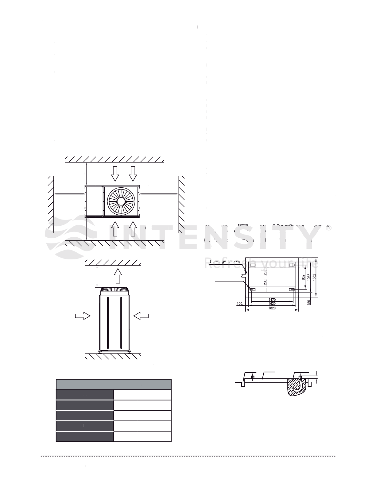
In the cace of extremely strong wind, please prevent the air
from flowing backwards into the outdoor unit.
Snow canopy is necessary in sonwfall places on the outdoor
unit. Please consult the local dealer for details.
In the frequent thunderstruck place, lightning proof actions
should be taken.
To prevent refrigerant leak, contact your dealer.
When the system is installed and runs in a small room, it is
required to keep the concentration of the refrigerant, if by any
chance coming out, below the limit. Otherwise, oxygen in the
room may be affected, resulting in a serious accident.
The refrigerant in the air conditioner is safe and normally does
not leak.
If the refrigerant leaks in the room, contact with a fire of a
burner, a heater or a cooker may result in a harmful gas.
Turn off any combustible heating devices, ventilate the room,
and contact the dealer where you purchased the unit.
Do not use the air conditioner until a service person confirms
that the portion where the refrigerant leaks is repaired.
WARNING
WARNING
Failure to observe a warning may result in death.
CAUTION
The safety precautions listed here are divided into two categories. In
either case, important safety information is listed which must be read
carefully.
Failure to observe a caution may result injury or damage
to the equipment.
CONTENTS PAGE
PRECAUTIONS..........................................................................1
TRANSPORTATION....................................................................................2
INSTALLATION OF THE UNIT.....................................................................3
WATER SYSTEM INSTALLATION ..............................................................5
ELECTRIC WIRING..................................................................................11
TRIAL RUN..............................................................................................16
USE.........................................................................................................17
MAINTENANCE AND UPKEEP..................................................................21
APPLICABLE MODELS AND MAIN PARAMETERS...............................27
ATTACHED DRAWING (I)......................................................................28
ATTACHED DRAWING (II).....................................................................29
1
installation
&
owner’s manual
1. PRE
C
A
U
TI
O
N
S
To prevent in
j
ur
y
to the user or other people and propert
y
damage, the
f
ollowing instructions must be
f
ollowed. Incorrect
operation due to ignoring o
f
instructions may cause harm o
r
dama
g
e.
Ask
y
our dealer for installation of the air conditioner.
Incomplete installation performed b
y
y
ourself ma
y
result in a
water leaka
g
e, electric shock, and fire.
Ask
y
our dealer for improvement, repair, and maintenance.
I
ncomp
l
ete
i
mprovement, repa
i
r, an
d
ma
i
ntenance may
result in a water leakage, electric shock, and
f
ire.
In order to avoid electric shock, fire or
inj
ur
y
, or i
f y
ou detect
an
y
abnormalit
y
such as smell of fire, turn off the powe
r
sup
ply
and call
yo
ur dealer
f
or instructions
.
Never replace a fuse with that of wron
g
rated current o
r
o
th
e
r wir
es
wh
e
n
a
f
use
b
l
o
w
s
ou
t.
U
se of wire or copper wire ma
y
cause the unit to break down
o
r
cause
a
fir
e
.
D
o not insert fingers, rods or other objects into the air inlet or
out
let
.
When the fan is rotatin
g
at hi
g
h speed, it will cause in
j
ur
y
.
Never use a flammable spra
y
such as hair spra
y
, lacquero
r
p
a
i
nt near t
h
e un
i
t.
It may cause a fire
.
CA
CA
C
C
UT
UT
UT
UT
T
UT
T
T
T
T
IO
O
O
O
O
O
N
N
N
N
N
Do not use the air conditioner for othe
r p
urp
oses.
I
n or
d
er to avo
id
an
y
qua
li
t
y
d
eter
i
orat
i
on,
d
o not use t
h
e un
i
t
for coolin
g
precision instruments, food, plants, animals or
works of art.
Before cleanin
g
, be sure to stop the operation, turn the
breaker off or
pul
l out the su
ppl
y c
ord.
Otherwise, an electric shock and in
j
ur
y
ma
y
result.
In order to avoid electric shock or fir
e,
make sure that an
ea
rth l
ea
k
de
t
ec
t
o
r i
s
in
s
t
a
ll
ed
.
Be sure the air conditioner is grounded.
I
n or
d
er to avo
id
e
l
ectr
i
c s
h
oc
k
, ma
k
e sure t
h
at t
h
e un
i
t
i
s
grounded and that the earth wire is not connected to gas or
water
pip
e,
lig
htn
ing
conductor or tele
pho
ne earth wire
.
In order to avoid injury, do not remove the
f
an guard o
f
the
ou
t
doo
r
u
n
i
t
.
D
o not o
p
erate t
h
e a
i
r con
di
t
i
oner w
i
t
h
a wet
h
an
d
.
A
n e
l
ectr
i
c s
h
oc
k
may
h
a
ppe
n.
Do not touch the heat exchanger
f
ins.
These fins are sharp and could result in cuttin
g
in
j
uries
.
N
ever inspect or service the unit b
y
y
oursel
f
.
A
sk a qualified service person to perform this work.
D
o not
di
spose t
hi
s pro
d
uct as unsorte
d
mun
i
c
i
pa
l
waste.Collection of such waste separatel
y
for special treatment
i
s necessary
.
Keep
f
ar awa
y
f
rom hi
g
h-
f
requenc
y
equipment
.
Keep awa
y
f
rom the
f
ollowin
g
places:
a
place where it is full of oil
g
as; places where salt
y
air
surrounding
(
near the coast
)
; a place where is caustic gas
(
the
sul
f
ide in hots
pri
ng)
. Location in the
f
ollin
g
places ma
y
cause
m
al
f
unction or shorten the li
f
e s
p
an o
f
the manchine.
I
n the cace o
f
extremel
y
stron
g
wind, please prevent the ai
r
f
rom
f
lowin
g
backwards into the outdoor unit.
S
now canop
y
is necessar
y
in sonw
f
all places on the outdoor
u
nit. Please consult the local dealer
f
or details
.
I
n the
f
requent thunderstruck place, li
g
htnin
g
proo
f
actions
s
h
ou
ld
b
e ta
k
en
.
To prevent refrigerant leak, contact your dealer.
Wh
en t
h
e s
y
stem
i
s
i
nsta
ll
e
d
an
d
runs
i
n a sma
ll
room,
i
t
i
s
required to keep the concentration of the refri
g
erant, if b
y
an
y
c
hance comin
g
out, below the limit.
O
therwise, ox
yg
en in the
room m
ay
be affected, resultin
g i
n a serious accident.
The refri
g
erant in the air conditioner is safe and normall
y
does
n
ot
l
ea
k
.
I
f the refri
g
erant leaks in the room, contact with a fire of a
burner, a heater or a cooker ma
y
result in a harm
f
ul
g
as
.
Turn o
ff
an
y
combustible heatin
g
devices, ventilate the room,
nd
nd
nd
and
nd
nd
nd
d
co
n
n
nta
ct
c
c
the
e
e
e
e
e
e
e
e
d
d
d
d
de
d
d
ale
le
l
l
e
e
r w
r
r
rw
r
r
r w
r
he
e
er
e
y
ou
u
u
u
pur
h
cha
se
ed
d
se
th
th
t
t
t
t
t
e
e
e u
e
e
e
e
nit
t
t
t
t
t
.
Do
o
o
o
o
o
o
o
no
no
no
not
no
no
no
no
us
e
e
e t
h
h
h
he
h
h
h
h
air
air
air
air
air
air
air
air
air
co
ndi
tio
o
o
ne
e
er
until a servic
e p
p
p
p
p
p
p
ers
ers
rs
rs
rs
rs
rs
rs
rs
on
n
n
n
n
n
n
n
n
con
f
irms
tha
a
a
a
t t
tt
t t
t t
t t
tt
t t
t
he
e
e
e
e
e
e
e
po
o
or
tio
n w
w
w
w
w
w
w
w
w
her
he
he
he
he
he
e
er
e t
t
t
t
t
t
t
t
he
h
h
h
h
h
r
r
ref
r
r
rig
era
nt
t
t
le
a
a
ks is
rep
p
air
a
a
a
a
a
a
a
a
ed
ed
ed.
ed
ed
ed
ed
e
WARNIN
G
WA
R
R
RN
I
I
IN
G
G
G
G
Fai
Fa
Fai
Fai
Fai
Fa
Fai
lur
lur
lur
lur
lur
lur
u
ur
r
eto
eto
eto
to
eto
t
eto
to
o
eto
obs
obs
obs
obs
obs
s
obs
s
erve a warn
i
ng may res
ult
in
dea
th
h
th.
h
C
A
U
TI
O
N
The
sa
a
a
a
a
a
a
fet
f
f
f
f
f
f
y p
rec
aut
ut
ut
ut
ut
ut
ut
u
u
ion
ion
ion
ion
ion
on
ion
n
n
s l
s
s
s
s
s
s
s
s
isted here are divided into two cate
gor
ies. In
eit
her
er
er
er
er
er
er
e
e
e
ca
se,
im
im
im
im
im
m
m
im
por
por
po
po
po
por
por
por
tan
tan
tan
an
an
tan
tan
t s
t s
t
t s
t s
t s
t s
ts
s
s
af
af
afe
a
af
a
af
a
af
a
t
y
in
f
ormation is listed which must be read
car
efu
f
fu
fu
fu
fu
f
u
lly
lly
lly
lly
lly
ly
.
F
a
il
ure to o
b
serve a caut
i
on may resu
l
t
i
n
j
ury or
d
amage
to t
h
e equ
i
pment
.
CO
NTENT
S
P
A
G
E
PRE
CAU
TIO
NS.
........................................................................
.1
TRA
NSP
ORT
ATI
ON.
...
...
...
...
...
...
...
...
...
...
...
...
...
...
...
...
...
...
...
...
...
...
...
...
...
...
...
..2
INS
TAL
LAT
ION
OF
TH
E U
NIT
.....................................................................
3
WATER
S
Y
S
TEM IN
S
TALLATI
O
N ..............................................................5
ELE
C
TRI
C
WIRIN
G
..................................................................................1
1
TRIAL RUN.............................................................................................
.16
US
E.........................................................................................................
17
MAI
NTE
NAN
CE
AND
UP
KEE
P. .
...
...
...
...
...
...
...
...
...
...
...
...
...
...
...
...
...
...
...
...
...
.21
APP
LIC
ABL
E M
ODE
LS
AND
MA
IN
PAR
AME
TER
S..
...........................
..2
7
ATT
ACH
ED
DRA
WIN
G
(
I
)
......................................................................2
8
ATT
ACH
ED
DRA
WIN
G
(
II
)
.....................................................................2
9

2
installation & owner’s manual
After a long use, check the unit stand and fitting for damage.
If damaged, the unit may fall and result in injury.
To avoid oxygen deficiency, ventilate the room sufficiently if
equipment with burner is used together with the air
conditioner.
Arrange the drain hose to ensure smooth drainage.
Incomplete drainage may cause wetting of the building,
furniture etc.
Never expose little children, plants or animals directly to the
air flow.
Adverse influence to little children, animals and plants may
result.
Notice to avoid places where operation noise may easily be
spread away or be enhanced.
Noise can be amplified by anything blocking the air outlet of
outdoor unit.
Choose a proper place that the noise and hot or cold wind
blown out of the outdoor unit will not bring inconvenience to
your neighbors and not affect the growth or animal or plant.
Recommending locate and operate the equipment at the
altitude height not exceeded than 1000m.
2. TRANSPORTATION
Endurable temperature during transportation is -25°C~55°C.
Such equipment could endure 70°C of the maximum
temperature in 24hrs.
Do not allow a child to mount on the outdoor unit or avoid
placing any object on it.
Falling or tumbling may result in injury.
Do not operate the air conditioner when using a room
fumigation - type insecticide.
Failure to observe could cause the chemicals to become
deposited in the unit, which could endanger the health of
those who are hypersensitive to chemicals.
Do not place appliances which produce open fire in places
exposed to the air flow from the unit or under the indoor unit.
It may cause incomplete combuston or deformation of the
unit due to the heat.
Do not install the air conditioner at any place where
flammable gas may leak out.
If the gas leaks out and stays around the air conditioner, a
fire may break out.
The appliance is not intended for use by young children or
infirm persons withoutsupervision.
Young children should be supervised to ensure that they do
not play with the appliance.
Fig. 2-1 Lifting of the unit
Handling of the unit
The angle of inclination should not be more than 15º when carrying the unit, to avoid overturn of the unit.
a. Rolling handling: several rolling rods of the same size are placed under the base of the unit, and the length of each rod must be more
than the outer frame of the base and suitable for balancing of the unit.
b. Lifting: the strength lifting rope (belt) can bear should be 4 times the weight of the unit. Check the lifting hook and ensure that it is firmly
attached to the unit, and the lifting angle should be more than 60º. To avoid damages to the unit, the contact position of the unit and lifting
rope should be provided with an at least 50mm thick wood block, cloth or hard paper. Any person is not allowed to stand below the unit
when lifting it.
Lifting angle
The position should be provided with an at
least 50mm thick wood block, cloth or hard
paper, to avoid damages to the unit.
2
i
nstallation
&
owner’s manual
After a lon
g
use, check the unit stand and fittin
g
for dama
g
e.
I
f
dama
g
ed, the unit ma
y
f
all and result in in
j
ur
y.
To avoid ox
yg
en deficienc
y
, ventilate the room sufficientl
y
i
f
equ
i
pment w
i
t
h
b
urner
i
s use
d
toget
h
er w
i
t
h
t
h
e a
ir
co
n
dit
ion
e
r
.
A
rran
g
e t
h
e
d
ra
i
n
h
ose to ensure smoot
h
d
ra
i
na
g
e
.
Incomplete draina
g
e ma
y
cause wettin
g
of the buildin
g
,
f
u
rnit
u
r
e
e
t
c.
N
ever expose
li
tt
l
e c
hild
ren, p
l
ants or an
i
ma
l
s
di
rect
ly
to t
h
e
a
ir fl
o
w.
Adverse influence to little children, animals and plants ma
y
r
es
ult
.
Notice to avoid places where operation noise ma
y
easil
y
be
sprea
d
awa
y
or
b
e en
h
ance
d
.
Noise can be am
pli
fied b
y a
nyt
hin
g b
lockin
g t
he air outlet of
out
doo
r u
nit
.
C
hoose a proper place that the noise and hot or cold wind
blown out of the outdoor unit will not brin
g
inconvenience to
y
our nei
g
hbors and not affect the
g
rowth or animal or plant.
R
ecommen
di
n
g
l
ocate an
d
operate t
h
e equ
i
pment at t
h
e
a
ltitude hei
g
ht not exceeded than 1000m.
2
. TRAN
S
P
O
RTATI
O
N
Endurable temperature durin
g
transportation is -25°C~55°C.
S
uch e
qui
pme
nt could endure 70
°C
o
f
the maximum
temperature in
2
4hrs.
Do
n
o
t
allo
w
a
child
t
o
m
ou
nt
o
n t
he
ou
t
doo
r
u
n
i
t
o
r
a
v
oid
p
l
ac
i
ng any o
bj
ect on
i
t.
F
a
lli
ng or tum
bli
ng may resu
l
t
i
n
i
n
j
ury
.
D
o not operate t
h
e a
i
r con
di
t
i
oner w
h
en us
i
n
g
a room
f
umi
g
ation - t
y
pe insecticide.
F
a
il
ure to o
b
serve cou
ld
cause t
h
e c
h
em
i
ca
l
s to
b
ecome
deposited in the unit, which could endan
g
er the health o
f
t
h
ose w
h
o are
h
ypersens
i
t
i
ve to c
h
em
i
ca
l
s.
Do not
pl
ace a
p
pli
ances which
p
roduce o
p
en fire in
pla
ces
ex
p
osed to the air
f
low
f
rom the unit or under the indoor unit.
It
may
cause incom
ple
te combuston or deformation of the
un
i
t
d
ue to t
h
e
h
eat.
D
o not
i
nsta
ll
t
h
e a
i
r con
di
t
i
oner at a
ny
p
l
ace w
h
ere
f
lammable
g
as ma
y
leak out.
If the
g
as leaks out and sta
y
s around the air conditioner, a
f
ire m
ay
break out.
The appliance is not intended
f
or use b
y
y
oun
g
children or
in
f
irm
p
ersons withoutsu
p
ervision
.
Y
oun
g
c
hild
ren s
h
ou
ld
b
e superv
i
se
d
to ensure t
h
at t
h
e
y
d
o
not p
l
a
y
w
i
t
h
t
h
e app
li
ance
.
Fig.
2
-
1
Li
f
ting o
f
the unit
Han
Han
Han
Han
an
an
an
an
dli
d
dli
dli
dli
dl
dl
dli
dli
ng
ng
ng
ng
ng
ng
ng
ng
ng
of
of
of
of
of
of
o
of
of
the
the
th
the
the
the
the
the
the
un
un
un
un
un
un
n
n
n
i
t
The
The
he
e
The
The
he
h
Th
an
an
an
an
an
an
an
n
gle
gle
g
gle
gl
g
g
g
of
of
of
of
of
of
of
o
f
incli
nat
nat
nat
nat
nat
nat
nat
a
ion
i
i
i
i
i
i
sh
o
o
oul
d
d
d n
o
o
t
t
be
mor
m
mor
mor
m
m
m
m
m
e t
han
han
han
han
15
15
15
º w
º
º w
w
w
h
h
hen
ca
a
rry
y
y
i
ing
ing
th
th
th
e u
n
n
n
nit
, t
o a
o a
a
a
o a
a
a
a
vo
o
oi
d
o
ve
e
e
er
e
e
e
e
tur
ur
ur
ur
ur
ur
ur
ur
u
n o
o
o
o
o
o
o
o
o
ft
f
f t
ft
ft
ft
ft
ft
he
u
u
uni
t
t
t.
a
a
a
a
a.
a
a
a
a
R
R
R
Rol
R
R
lin
in
in
lin
in
in
in
in
li
gh
gh
gh
gh
gh
gh
g h
gh
and
and
andand
and
and
and
a
a
lin
lin
lin
lin
lin
in
in
n
g:
g:
g:
g:
g:
g:
g:
g:
s
s
sev
s
s
s
s
s
era
l
l
r
o
o
ll
ing
g
g
ro
o
ds
ds
ds
ds
ds
ds
ds
ds
of
of
of
of
of
of
of
of
of
the
the
the
e
sa
me
siz
z
z
z
e are
p
p
pla
ced
un
n
n
der
r
th
e b
e b
e b
e b
e
e b
eb
e b
ase
as
as
ase
se
as
as
s
s
o
o
of
th
e u
eu
e u
e u
e u
e u
u
u
u
nit
, a
a
a
a
a
a
a
a
nd
n
n
n
n
n
n
n
th
h
he
le
e
e
n
g
t
h o
o
o
f e
e
e
ach ro
d m
m
m
m
m
m
m
m
u
st
t
t
t
t
t
t
b
b
b
be
b
b
m
o
r
e
tha
tha
tha
tha
tha
thatha
h
h
n t
n t
n t
n t
n t
n t
n t
n t
n
he
he
he
he
e
e
e
e
outer
f
fra
fra
fra
fra
fra
fra
fra
fra
me
me
me
me
me
me
m
e
e
o
f
the
ba
a
se
a
a
a
and
d
su
ita
it
it
it
it
it
ita
t
ble
e
e
e
f
or b
a
la
n
n
n
nci
n
g
of
the
e
e
e
un
un
un
it.
it.
b.
b
b
b
b
b
b
b
Lif
f
f
f
f
f
f
tin
tin
t
tin
in
tin
tin
g:
g
g:
g:
g:
g:
g:
the
he
he
he
he
he
he
e
e
st
s
s
s
s
s
ren
en
n
n
n
n
n
n
g
g
g
gth
g
g
g
g
lifti
ng
g
g
g
g
g
ro
o
rop
ro
o
ro
e (
(
(
(
(
(
be
e
bel
be
e
be
t
)
can
n
n
n
n
n
n
n
b
b
be
be
b
ar
sho
o
o
o
uld
d
uld
uld
uld
d
be 4
tim
t
tim
t
tim
tim
es
es
es
es
the
e
the
the
e
the
we
e
igh
igh
igh
igh
h
t of t
he
h
he
h
h
he
he
h
u
u
uni
u
u
u
t.
Che
Ch
Che
Che
Ch
Ch
Che
Ch
he
ck
ck
ck
ck
ck
ck
ck
ck
k
t
t
the
t
li
i
i
i
fti
fti
fti
fti
n
n
ng
n
n
n
hoo
k a
ka
ka
ka
n
n
nd
n
ensure
th
th
th
th
a
a
a
at
a
a
a
it is firml
y
at
at
at
att
at
att
att
a
a
ached
to
the
the
the
the
the
the
the
th
he
unit, and the li
f
tin
g
an
g
le should be more than 60
º
. To avoid dam
age
s to the unit, the contact position o
f
the unit and li
f
tin
g
rop
e s
s
s
s
s
s
hou
hou
hou
hou
hou
hou
hou
hou
ld
ld
ld
ld
ld
ld
ld
be provided with an at least 5
0
mm thick wood block, cloth or
ha
ha
ha
ha
h
h
ha
rd
rd
rd
rd
rd
rd
r
rd
r
pap
pap
pap
pap
pap
pa
pa
pa
pa
er
e
er
er.
e
er
e
An
An
An
An
A
An
An
AnAn
y p
y p
y p
y p
y p
y p
y p
y p
ers
ers
ers
ers
ersers
ers
ers
r
on
on
on
on
n
n
n
n
is
is
is
is
is
i
is
is
not
o
o
o
o
o
o
o
al
al
a
a
al
a
al
al
a
low
low
low
ow
ow
low
low
low
low
ed
ed
d
d
ed
d
ed
to
to
t
t
to
to
o
sta
sta
sta
sta
st
sta
sta
sta
st
nd
d
d
d
d
be
be
bel
be
be
bel
be
be
be
ow
o
ow
ow
ow
ow
w
w
w
the
th
th
th
th
th
th
th
h
unit
w
hen li
f
tin
g
it.
Liftin
g
an
g
le
The
p
osition should be
p
rovided with an
at
l
east 5
0
mm thick wood block
, c
loth or hard
p
aper, to avoid dama
g
es to the unit.

3
&*/0((0&+*+3*".7/)*1(
3. INSTALLATION OF THE UNIT
"(" 0&+*+#&*/0((0&+*/&0"/
%"1*&0 * " &*/0(("!+* 0%" $.+1*! +.+*0%"
/1&0(" .++# 10 "*+1$% 2"*0&(0&+* 2+(1)" /%+1(! "
"*/1."!&*+0% /"/
%" 1*&0 /%+1(! *+0 " &*/0(("! 3%"." *+&/" *!
2&.0&+*."."-1&."!0+ ".0&*"40"*0
%" &*/0(("! 1*&0 /%+1(! " /%"(0"."! #.+) !&." 0
/1*(&$%0 / )1 % / ,+//&(" *! " #. 35 #.+)
+&(".#(1"/*!)&"*0&.3%& %)5".+!" +*!"*/".
+&(/*! +,,".01",.0/+#0%"1*&0
# 0%" &*/0(("! 1*&0 * " ,,.+ %"! 5
1*10%+.&6"! ,"./+*/ /#"05 )"/1."/ +# &/+(0&+*
/%+1(! " 0'"* /1 % / .&( $1.!/ %"/" )"/1."/
3&(( 2+&! .0&#& &( !)$"/ *! &!"*0( !)$"/
*!,."2"*00%" +*0.+(+4"/#.+)"&*$+,"*"!("!&*$
0+"4,+/1."+#"(" 0.& +),+*"*0/&*+,".0&+*
%"%"&$%0+#0%"&*/0((0&+*#+1*!0&+*#+.0%"1*&0
/%+1(! *+0 " ("// 0%* )) *! #(++. !.&*/ ."
."-1&."!&*&*/0((0&+* /&0"/ 0+"*/1." /)++0% !.&*$"
*!.")+2"*5/"",".
* /"+#&*/0((0&+*+*0%"$.+1*!0%"/0""(/"
+#0%"1*&0/%+1(!"(+ 0"!+*0%" +* ."0"#+1*!0&+*
*! 0%" +* ."0",(&*0% /%+1(! "40"*! "(+3 #.+6"*/+&(
(5".%"#+1*!0&+*+#0%"1*&0/%+1(!*+0" +**" 0"!
0+ 0%" #+1*!0&+* +# 0%" 1&(!&*$ 0+ 2+&! ##" 0&*$ 0%"
,"+,(" !1" 0+ 0.*/#". +# *+&/" *! 2&.0&+* %" /"
+# 0%"1*&0&/ ,.+2&!"! 3&0% &*/0((0&+* %+("/3%& % *
"1/"!0+ +**" 00%"1*&0*!0%"#+1*!0&+*#&.)(5
* /" +# &*/0((0&+* +* 0%" .++# 0%" .++# )1/0
,+//"// "*+1$% /0."*$0% 0+ /1/0&* 3"&$%0 +# 0%" 1*&0
*!)&*0"** ","./+**"( %" 1*&0 * " /1,,+.0"!
+* +* ."0"#+1*!0&+*/ +. %**"(/0""( #.)"/ /&)&(.
0+0%+/"1/"!&*0%" 1*&0&*/0((0&+*+* 0%"$.+1*!%"
(+!".&*$ %**"(/0""()1/0"&*(&$*)"*03&0%0%"
&*/0((0&+* %+("/ +# 0%" 1*&0 !),". *! 0%" %**"(
/0""( /%+1(! ,+//"// "*+1$% 3&!0% #+. &*/0((&*$ 0%"
!),".
+*/1(0 0%" 1&(!&*$ +*0. 0+. 0%" . %&0" 01.(
!"/&$*".+.+0%"./," &(&/0/+100%" /"/3&0%/," &(
&*/0((0&+*."-1&.")"*0/
%"/"(" 0"!&*/0((0&+*/&0"+#0%"1*&0/%+1(!# &(&00" +**" 0&+*
+#30".,&,"/*!3&."/*!"#.""#.+)30".&*("0+#+&(#1)"
/0")+.+0%".%"0/+1. "/"/&!"/0%"*+&/"+#0%"1*&0*! +(!
*! %+0 &. /%+1(! *+0 &*#(1"* " 0%" /1..+1*!&*$ "*2&.+*)"*0
10(&*"!&)"*/&+*(!.3&*$1*&0))
"#02&"3
+,2&"3
("
#0". &*/0((&*$ 0%" /,.&*$ !),". 0%" 0+0( %"&$%0 +# 0%" 1*&0
3&((&* ."/"5))+./+
%",+.0/+#&*("0*!+10("0,&,"//%+1(!"#(*$",+.0/*!
#(*$"//%+1(!"%1"!/(&,+*3"(!&*$/0""(,&,"#(*$"/
+!"(
.+*02&"3
3
&*/0((0&+*
+3*".7/)*1(
3.
IN
S
TALLATI
O
N
O
F THE
U
NIT
"(" 0&+*+
#
&*/0((0&+*/&0"/
%"1*&0 * " &*/0(("!+*0%"
$
.+1*! +. +* 0%"
/
1&0(" .++
#
10 "*+1
$
% 2"*0&(0&+* 2+(1)" /%+1(! "
"*/
1."
!&
*
+0%
/"/
%" 1*&0 /%+1(! *+0 " &*/0(("! 3%"." *+&/" *!
2&.0&+*."."-1&."!0+ ".0&*"40"*0
%"
&*
/0
(("
! 1
*&0
/%
+1(
!
" /
%"(
0".
"!
#.+
) !
&."
0
/1
*(
&
$
%0
/
)1 % / ,+//&(" *! "
#
.
3
5
#
.+)
+&(".#(1"/*!)&"*0&.3%& %)
5
".+!" +*!"*/".
+&(/*! +,,".01",.0/+#0%"1*&0
# 0%" &
*
/0
((
"!
1*
&0
*
"
,,.+
%"!
5
1*1
0
%+
.&
6
"!
,"./+*
/
/
#"0
5
)"/1.
"/
+#
&
/+
(
0&
+
*
/
%+1(! " 0'"* /1 % / .&(
$
1.!/ %"/" )"/1."/
3&(
(
2
+
&
!
.
0&#
&
&
(
!)
$"
/
*
!
&!
"*
0(
!)
$
"/
*!,."2"*00%" +*0.+(+4"/#.+)"&*
$
+,"*"!("!&*
$
0+
"4,
+/1."+
#
"(" 0.& +)
,+*
"*0/&*+
,".
0&+*
%"%"&
$
%0+#0%"&*/0((0&+*#+1*!0&+*#+.0%"1*&0
/
%+1(! *+0 " ("// 0%* )) *!
#
(++. !.&*/ ."
.
"-1&."!&*&*/0((0&+* /&0"/ 0+"*/1." /)++0% !.&*
$
"
*!.")+2"*
5
/"",".
* /"+
#
&*/0((0&+*+*0%"
$
.+1*!0%"/0""(/"
+
#
0%"1*&0/%+1(!"(+ 0"!+*0%" +* ."0"
#
+1*!0&
+*
*! 0%" +* ."0",(&*0% /%+1(! "40"*! "(+3
#
.+6"* /+&(
(
5
".%"
#
+1*!0&+*+
#
0%"1*&0/%+1(!*+0" +**" 0"!
0+
0%
"
#
+1
*
!
0&
+*
+# 0%" 1&(!&*
$
0+ 2+&! ##" 0
&*$
0%"
,
"+,(" !1" 0+ 0.*/#". +# *+&/" *! 2&.0&+* %" /"
+# 0%"1*&0&/ ,.+2&!"! 3&0% &*/0((0&+* %+("/3%& % *
"1/"!0+ +**" 00%"1*&0*!0%"#+1*!0&+*#&.)
(5
* /" +# &*/0((0&+* +* 0%" .++# 0%" .++# )1/0
,
+//"// "*+1
$
% /0."*
$
0% 0+ /1/0&* 3"&
$
%0 +# 0%" 1*&0
*!)
&*0
&*0
&*0
*0
*0
&*0
&*0
&*0
*0
"*
"*
"*
"*
"*
"*
"*
*
* "
,"
./+**"(%"1*&0 * "/1
,,+
.0"!
+
*
+*
+*
+*
+*
+*
+*
+*
+*
+
."
0"
0
0"
0"
0
0"
#+1
+1
#+1
#+1
#+1
#+1
#+1
+
*!
*
*
*
*
*
0&
+
*
/
+
.
%
**
"
(
/
0
""
(#
.
)
"/
/
&)&(
.
0
0
0
0
0+
0
0
0
0%+
%+
%+
%+
%+
%+
%
/"
/"
/"
/"
/"
/"
/
/
1/"
"
"
"
"
"
"
!&
!
!
!
!
!
!
!
!
*0
%"1*&
0
&
0
0&
*
*/0
*
(
(
(
(
(
(
0&
&
&
0&
&
+
+
+*
+
+
+
+
+
+
+*
*
*
%
%
%
%"
0%
%
$
$
$
$.
+1*
!
!
%
%
%"
%
(+
+
+
+
+
+
+
+
!
!
!
!
!
!
!
!
!
".
.
.
.
.
.
.
&*$
&*$
&*$
&*$
&*$
&*$
*$
*$
%
**
*
*
*
*
*
*
*
"(
/0"
"
"
"(
)1/
/
/
/
0
"&
"&
"&
"&
"&
"
&
"&
*
*
*
*
*
*
*
*
(&
$
*
*
*)"
*0
3&0
0
0
0
%0%"
&*/
/
/
/
/
/
0(
0(
0(
0(
(
0(
0(
0
(
(
(
(
(0
(0
(
&+*
&
&+*
&+*
+*
+*
+*
&+*
*
%+%+
%+
("/
("/
("/
("/
("/
("/
"/
"/
+#
0%
"
1
*
*
*&0
!
!
!
!
),"
),"
),"
,"
,"
,"
,"
,"
.
*
*
!
0%
"
%
*
*"(
/
/
/
/
/
/
/
/
0"
0"
0"
"
0"
0"
0"
0"
0
"(
"(
"
"
"(
"
"(
/%+
/%
/%
/%
/%
/%
/%
/%
/%
1(! ,
+
/
/
//
/
/
/
/
/
/
"//
"
"
"
*+
+
+1
$%
%
%
3
3
3&
!0%
%
%
%
%
%
%
%
#+
.
&
*/0
(
(
&*$
$
$
$
0%
"
!)
!)
!)
!)
!)
!)
!)
!
,".
,".
,".
,".
,".
,".
,".
".
+*
*
*
/1(
/
/1
/1
/1
/1
/1
/1
1
0 0%" 1&(!&*
$
+*0. 0+. 0%" . %&0" 01.(
!"/&
$
*".+.+0%"./," &(&/0/+100%" /"/3&0%/," &(
&*/0((0&+*."
-1&
.")"*0/
%
"
/"
(
"
0
"!
&*
/
0
((
0&
+
*
/
&0
"
+#
0%
"
1
*&0
/
%
+1
(
!
#
&(&0
0
"
+
**
"
0&
+
*
+
#
30".,&,"/*!3&."/*!"
#
.""
#
.+)30".&*("0+
#
+&(
#
1)"
/
0")+.+0%".%"0/+1. "/"/&!"/0%"*+&/"+#0%"1*&0*! +(!
*! %+0 &. /%+1(! *+0 &*
#
(1"* " 0%" /1..+1*!
&*$
"*2&.+*)"*0
10(&*"!&)"*/&+*(!.3&*
$
1*&0))
"#
02&
"
3
+
+
,
2
2
2&
"3
("
"
"
"
"
"
#
0". &*/0((&*
$
0%" /,.&*
$
!),". 0%" 0+0( %"&
$
%0 +
#
0%" 1*&0
3&((&* ."/"
5
))+./+
%",+.0/+
#
&*("0*!+10("0,&,"//%+1(!"
#
(*
$
",+.0/*!
#
(
*$"
//%+1(!"%1"!/(&,+*3"(!&*
$/
0""(,&,"
#
(
*$
"/
+!
+
+
+
"(
.+
*0
2&"
3

4
installation & owner’s manual
3.3 Requirements of arrangement space of the unit
3.3.1 Requirements of arrangement space of the unit
3.3.1.1 To ensure adequate airflow entering the condenser,
the influence of descending airflow caused by the high-rise
buildings around upon the unit should be taken into account
when installing the unit.
3.3.1.2 If the unit is installed where the flowing speed of air is
high, such as on the exposed roof, the measures including
sunk fence and Persian blinds can be taken, to prevent the
turbulent flow from disturbing the air entering the unit. If the
unit needs to be provided with sunk fence, the height of the
latter should not be more than that of the former; if Persian
blinds are required, the total loss of static pressure should be
less than the static pressure outside the fan. The space
between the unit and sunk fence or Persian blinds should also
meet the requirement of the minimum installation space of the
unit.
3.3.1.3 If the unit needs to operate in winter, and the
installation site may be covered by snow, the unit should be
located higher than the snow surface, to ensure that air flows
through the coils smoothly.
Fig. 3-2
Input of airflow
Input of airflow
Input of airflowInput of airflow
Installation space (mm)
A
B
C
D
E
Ő
Ő
Ő
Ő
Ő
3.4 Space requirements for parallel installation of
multiple modular units
To avoid back flow of the air in the condenser and operational
faults of the unit, the parallel installation of multiple modular
units can follow the direction A and D as shown in Fig. 3-2, the
spaces between the unit and the obstacle are given in Table
3.1, and the space between adjacent modular units should not
be less than 300mm; the installation can also follow the
direction B and C as shown in Fig. 3-2, the spaces between the
unit and the obstacle are given in Table 3-1, and the space
between adjacent modular units should not be less than
600mm; the installation can also follow the direction
combination of A and D, and B and C, the spaces between the
unit and the obstacle are given in Table 3-1, the space
between adjacent modular units in the direction A and D should
not be less than 300mm, and the space between adjacent
modular units in the direction B and C should not be less than
600mm. If the spaces mentioned above cannot be met, the air
passing from the unit to the coils may be restricted, or back
flow of air discharge may occur, and the performance of the
unit may be affected, or the unit may fail to operate.
3.5 Installation foundation
a. The unit should be located on the horizontal foundation, the
ground floor or the roof which can bear operating weight of the
unit and the weight of maintenance personnel. Refer to Table
9.1 (Table of applicable models and parameters) for operating
weight.
b. If the unit is located so high that it is inconvenient for
maintenance personnel to conduct maintenance, the suitable
scaffold can be provided around the unit.
c. The scaffold must be able to bear the weight of maintenance
personnel and maintenance facilities.
d. The bottom frame of the unit is not allowed to be embedded
into the concrete of installation foundation.
3.5.1 Location drawing of installation foundation of the unit: (unit:
mm)
Schematic diagram of installation dimension of the unit
Concrete Cement mortarDrainage channel
Table 3-2
Fig. 3-3
Fig. 3-4
$
%
'
&
(
Drainage channel
Anchor bolt
4
installation & owner’s manual
3.3 Requirements o
f
arran
g
ement space o
f
the uni
t
3.3.1 Requirements o
f
arrangement space o
f
the uni
t
3.3.1.1 To ensure adequate airflow entering the condenser,
the in
f
luence o
f
descendin
g
air
f
low caused b
y
the hi
g
h-rise
buildin
g
s around upon the unit should be taken into account
wh
en
i
nsta
lli
n
g
t
h
e un
i
t.
3.3.1.2 If the unit is installed where the flowin
g
speed of air is
hig
h, such as on the
exp
osed roo
f
, the measures includ
ing
sunk fence and Persian blinds can be taken, to
p
revent the
turbulent
f
low
f
rom disturbin
g
the air enterin
g
the unit. I
f
the
u
nit needs to b
e p
rovided with sunk fence, the h
eig
ht of the
l
atter should not be more than that o
f
the
f
ormer
;
i
f
Persian
blinds are re
q
uired, the total loss of static
p
ressure should be
l
ess than the static
pre
ssure outside the
f
an. The
spa
ce
between the unit and sun
k f
ence or Persian blinds should also
meet the re
q
uirement o
f
the minimum installation s
p
ace o
f
the
u
n
i
t.
3.3.1.3 I
f
the unit needs to o
p
erate in winter, and the
i
nsta
ll
at
i
on s
i
te ma
y
b
e covere
d
by
snow, t
h
e un
i
t s
h
ou
ld
b
e
l
ocated h
igh
er than the snow sur
f
ace, to ensure that air
f
lows
t
h
rou
gh
t
h
e co
il
s smoot
hly
.
F
i
g
. 3-2
Inp
ut o
f
air
f
low
I
n
np
u
u
u
ut
o
o
o
of
air
f
lo
w
I
n
p
ut o
f
air
f
lo
w
I
n
p
ut o
f
air
f
lo
w
I
nstallation space
(
mm
)
A
B
C
D
E
Ő
Ő
Ő
Ő
Ő
3.4
Sp
ace re
q
uirements
f
or
p
arallel installation o
f
mu
l
t
ipl
e mo
d
u
l
ar un
i
t
s
To avoid back
f
low o
f
the air in the condenser and operational
f
aults of the unit, the
p
arallel installation of multi
p
le modula
r
u
nits can
f
ollow the direction A and D as shown in Fig. 3-2, the
spaces
b
etween t
h
e un
i
t an
d
t
h
e o
b
stac
l
e are g
i
ven
i
n
T
a
bl
e
3
.
1
, and the space between
adj
acent modular units should not
be less than 300mm; the installation can also
f
ollow the
direction B and C as shown in Fi
g
. 3-2, the spaces between the
u
nit and the obstacle ar
e g
iven in Table 3-1, and the
spa
ce
b
etween a
dj
acent mo
d
u
l
ar un
i
ts s
h
ou
ld
not
b
e
l
ess t
h
an
6
00mm
;
the installation can also follow the direction
c
ombination of A and D, and B and C, the s
pac
es between the
u
nit and the obstacle are
g
iven in Table 3-1, the space
b
etween a
dj
acent mo
d
u
l
ar un
i
ts
i
n t
h
e
di
rect
i
on
A
an
d
D
s
h
ou
ld
n
ot be less than 300mm, and the space between ad
j
acent
m
odular units in the direction B and
C
should not be less than
6
00mm. If the s
p
aces mentioned above cannot be met, the ai
r
p
assin
g
from the unit to the coils ma
y
be restricted, or back
f
low of air dischar
g
e ma
y
occur, and the performance of the
u
nit ma
y
be affected, or the unit ma
y
fail to operate.
3.
5
In
st
al
la
ti
on
f
ou
nd
at
io
n
a
. The unit should be located on the horizontal
f
oundation, the
g
round
f
loor or the roo
f
which can bear operatin
g
wei
g
ht o
f
the
u
nit and the wei
g
ht of maintenance personnel. Refer to Table
9
.1
(
Table o
f
applicable models and parameters
)
f
or operatin
g
we
igh
t.
b. If the unit is located so hi
g
h that it is inconvenient for
m
aintenance
p
ersonnel to conduct maintenance, the suitable
scaffold can be
p
rovided around the unit.
c
. The scaffold must be able to bear the w
eig
ht of maintenance
p
ersonnel and maintenance facilities.
d
d
d
d.
The
bo
b
bo
b
bo
bo
tto
t
t
t
t
t
m f
f
f
f
f
f
f
f
ram
ram
ram
am
ram
ram
ram
ram
e o
e o
e o
e o
eo
e o
eo
o
f t
he
e
e
e
e
e
uni
u
u
u
t i
i
i
i
sn
sn
s n
ot
ot
ot
ot
all
all
all
all
owe
owe
we
e
e
owe
e
e
e
dt
dt
t
dt
d t
o b
o
o
o
o
o
o
e e
e
e
e
e
e
e
e
mbe
mb
b
mb
b
mb
b
b
b
dde
dde
dd
dde
dde
dde
dde
dd
d
d
i
nt
o t
ot
o t
o t
ot
ot
o t
t
h
e
co
o
on
cre
e
e
e
e
e
e
e
te
e
e
e
e
e
e
f
f
f
f
f
f
f
of
f
ins
ins
ins
ins
ins
ins
ins
ns
s
t
a
l
la
a
at
io
o
on
fo
und
d
d
und
d
ati
t
i
t
i
on
on.
3
3
3
3.5
.
1
Loc
L
Loc
Loc
L
Loc
Lo
Lo
L
a
ati
a
o
o
on
dra
ra
r
ra
ra
ra
ra
win
win
win
wi
win
wi
win
win
win
g o
g o
g
g
g
g
g
g
g
f i
f
f
f
f
f
f
ns
s
st
al
l
ll
ation
f
f
fou
n
nda
tion o
f
t
f
he
e
e
e
unit:
(
unit:
mm)
mm
mm
mm
S
chematic dia
g
ram of installation dimension of the uni
t
C
oncrete
C
ement morta
r
D
ra
i
na
g
e c
h
anne
l
Table
3
-
2
F
i
g
. 3-
3
Fig
. 3-
4
$
%
'
&
(
Dra
Dra
Dra
Dra
Dra
Dra
Dra
Dra
Dra
a
ina
ina
in
ina
ina
ina
n
n
na
ge
ge
ge
g
ge
g
g
cha
cha
cha
cha
cha
cha
cha
cha
ha
nne
nne
nne
nne
nne
nne
nne
nne
nne
l
A
nchor bolt

5
installation & owner’s manual
3.6 Installation of damping devices
3.6.1 Damping devices must be provided between the unit
and its foundation.
By means of the Φ15mm diameter installation holes on the
steel frame of the unit base, the unit can be fastened on
the foundation through the spring damper. See
Fig.3-3(Schematic diagram of installation dimension of the
unit) for details about center distance of the installation
holes. The damper does not go with the unit, and the user
can select the damper according to the relevant
requirements. When the unit is installed on the high roof or
the area sensitive to vibration, please consult the relevant
persons before selecting the damper.
3.6.2 Installation steps of the damper
Step 1. Make sure that the flatness of the concrete
foundation is within ±3mm, and then place the unit on the
cushion block.
Step 2. Raise the unit to the height suitable for installation
of the damping device.
c. Remove the clamp nuts of the damper.
Step 3. Place the unit on the damper, and align the fixing
bolt holes of the damper with the fixing holes on the unit
base.
Step 4. Return the clamp nuts of the damper to the fixing
holes on the unit base, and tighten them into the damper.
Step 5. Adjust the operational height of the damper base,
and screw down the leveling bolts. Tighten the bolts by
one circle to ensure equal height adjustment variance of
the damper.
Step 6. The lock bolts can be tightened after the correct
operational height is reached.
Damping device
Anchor bolt M12
Nut
Ferrol
It is recommended that the damper should be fastened on
the foundation with the provided holes. After the unit is
placed on the foundation, the damper connected with the
unit should not be moved, and the central clamp nut is not
allowed to be tightened before the damper sustains load.
Fig. 3-5
4. WATER SYSTEM INSTALLATION
4.1 Basic requirements of connection of chilled
water pipes
● After the unit is in place, chilled water pipes can be laid.
● The relevant installation regulations should be abided with
when conducting connection of water pipes.
● The pipelines should be free of any impurity, and all chilled
water pipes must conform to local rules and regulations of
pipeline engineering.
● Connection requirements of chilled water pipes
a. All chilled water pipelines should be thoroughly flushed, to be
free of any impurity, before the unit is operated. Any impurity
should not be flushed to or into the heat exchanger.
b. Water must enter the heat exchanger through the inlet;
otherwise the performance of the unit will decline.
c. The inlet pipe of the evaporator must be provided with a
target flow controller, to realize flow-break protection for the
unit. Both ends of the target flow controller must be supplied
with horizontal straight pipe sections whose diameter is 5 times
that of the inlet pipe. The target flow controller must be installed
in strict accordance with “Installation & Regulation Guide for
Target Flow Controller” (Figure 4.3~4.4). The wires of the target
flow controller should be led to the electric cabinet through
shielded cable (see Electric Controlling Schematic Diagram for
details). The working pressure of the target flow controller is
1.0MPa, and its interface is 1 inch in diameter. After the
pipelines are installed, the target flow controller will be set
properly according to the rated water flow of the unit.
d. The pump installed in the water pipeline system should be
equipped with starter. The pump will directly press water into
the heat exchanger of the water system.
e. The pipes and their ports must be independently supported
but should not be supported on the unit.
f. The pipes and their ports of the heat exchanger should be
easy to disassemble for operation and cleaning, as well as
inspection of port pipes of the evaporator.
g. The evaporator should be provided with a filter with more
than 40 meshes per inch at site. The filter should be installed
near to the inlet port as much as possible, and be under heat
preservation.
h. The by-pass pipes and by-pass valves as shown in Fig. 4-1
must be mounted for the heat exchanger, to facilitate cleaning
of the outside system of water passage before the unit is
adjusted. During maintenance, the water passage of the heat
exchanger can be cut off without disturbing other heat
exchangers.
i. The flexible ports should be adopted between the interface of
the heat exchanger and on-site pipeline, to reduce transfer of
vibration to the building.
j. To facilitate maintenance, the inlet and outlet pipes should be
provided with thermometer or manometer. The unit is not
equipped with pressure and temperature instruments, so they
need to be purchased by the user.
k. All low positions of the water system should be provided with
drainage ports, to drain water in the evaporator and the system
completely; and all high positions should be supplied with
discharge valves, to facilitate expelling air from the pipeline. The
discharge valves and drainage ports should not be under heat
preservation, to facilitate maintenance.
CAUTION
NOTE
5
i
nstallation & owner’s manual
3
.6 Installation o
f
da
mp
in
g
device
s
3
.
6
.
1
Damping devices must be provided between the unit
and
it
s f
oun
dat
ion
.
By
means o
f
the
Φ
15m
m d
iam
ete
r i
nst
all
ati
on
hol
es
on
the
s
teel frame of the unit base, the unit can be fastened on
t
he foundation throu
g
h the sprin
g
damper. See
F
i
g
.3-3
(
Schematic dia
g
ram of installation dimension of the
u
nit
)
for details about center distance of the installation
h
o
l
es.
Th
e
d
amper
d
oes not
g
o w
i
t
h
t
h
e un
i
t,
an
d
t
h
e user
c
an se
l
ect t
h
e
d
amper accor
di
ng to t
h
e re
l
evant
requirements. When the unit is installed on the hi
g
h roof o
r
th
e area sens
i
t
i
ve to v
ib
rat
i
on,
ple
ase consu
l
t t
h
e re
l
evant
p
ersons be
f
ore selectin
g
the damper.
3
.6.2 Installation steps o
f
the damper
Ste
p
1. Make sure that the flatness of the concrete
foundation is within ±3mm, and then
p
lace the unit on the
cushio
n
block
.
Step 2. Raise the unit to the hei
g
ht suitable for installation
of the dampin
g
device.
c. Remove the clam
p n
uts of the d
amp
er.
Step 3. Place the unit on the damper, and ali
g
n the fixin
g
bolt holes o
f
the damper with the
f
ixing holes on the unit
b
ase.
S
tep 4. Return the clamp nuts o
f
the damper to the
f
ixin
g
h
o
l
es on t
h
e un
i
t
b
ase, an
d
t
igh
ten t
h
em
i
nto t
h
e
d
amper.
S
tep 5. Ad
j
ust the operational hei
g
ht o
f
the damper base,
a
n
d
screw
d
own t
h
e
l
eve
li
ng
b
o
l
ts.
Ti
g
h
ten t
h
e
b
o
l
ts
b
y
one circle to ensure equal hei
g
ht ad
j
ustment variance o
f
t
h
e
d
amper.
S
te
p 6
. The lock bolts can be
tig
htened a
f
ter the correct
ope
rat
ion
ion
on
ion
on
on
on
ion
on
l
l
al
l
l
l
hei
h
he
h
h
he
h
he
h
gh
t
i
s reac
h
e
d
.
Dam
Da
Dam
Da
Dam
Dam
Dam
Dam
a
pin
pin
pin
pin
pin
pin
pin
pin
pin
gd
d
gd
g d
gd
gd
g
g
ev
i
c
e
An
An
n
c
hor
o
or
bo
bo
bo
lt
M12
M12
M12
N
Nut
Ferrol
It is recommended that the dam
per
should be
f
astened on
the
f
oundation with the
p
rovided holes. A
f
ter the unit is
placed on the
f
oundation, the damper connected with the
un
i
t s
h
ou
ld
not
b
e move
d
, an
d
t
h
e centra
l
c
l
amp nut
i
s not
allowed to be ti
g
htened be
f
ore the damper sustains load.
Fig
. 3-
5
4
. WATER
S
Y
S
TEM IN
S
TALLATI
O
N
4.1 Basic re
q
uirements o
f
connection o
f
chilled
water p
i
pes
●
A
f
ter the unit is in
p
lace, chilled water
p
i
p
es can be laid.
●
Th
e re
l
evant
i
nsta
ll
at
i
on
reg
u
l
at
i
ons s
h
ou
ld
b
e a
bid
e
d
w
i
t
h
when conductin
g
connection o
f
water pipes.
●
The pipelines should be
f
ree o
f
an
y
impurit
y
, and all chilled
water pipes must con
f
orm to local rules and re
g
ulations o
f
p
i
pe
li
ne en
gi
neer
i
n
g
.
●
C
onnection re
qui
rements o
f
chilled water
pi
p
e
s
a
. All chilled water pipelines should be thorou
g
hl
y
f
lushed, to be
f
ree o
f
an
y
impurit
y
, be
f
ore the unit is operated. An
y
impurit
y
s
hould not be
f
lushed to or into the heat exchan
g
er.
b
.
W
ater must enter t
h
e
h
eat exc
h
an
g
er t
h
rou
gh
t
h
e
i
n
l
et;
o
therwise the per
f
ormance o
f
the unit will decline.
c
. The inlet pipe o
f
the evaporator must be provided with a
t
ar
g
et
f
low controller, to realize
f
low-break protection
f
or the
u
nit. Both ends o
f
the tar
g
et
f
low controller must be supplied
w
ith horizontal strai
g
ht pipe sections whose diameter is 5 times
t
hat of the inlet pipe. The tar
g
et flow controller must be installed
i
n strict accordance with “Installation & Re
g
ulation Guide for
Tar
g
et Flow Controller”
(
Fi
g
ure 4.3~4.4
)
. The wires of the tar
g
et
f
low controller should be led to the electric cabinet throu
g
h
s
hielded cable
(
see Electric Controllin
g
Schematic Dia
g
ram for
d
etails
)
. The workin
g
pressure of the tar
g
et flow controller is
1
.0MPa
,
and its interface is 1 inch in diameter. After the
pip
elines are installed, the t
arg
g
g
g
et flow controller will be set
pro
pe
pe
pe
per
pe
pe
pe
pe
l
y
ac
c
cc
ord
d
d
d
d
d
d
ing
g
ing
ing
ing
ing
ing
g
to
to
to
to
to
t
to
to
to
th
th
h
h
h
h
h
h
h
e r
a
a
ate
d
d
d w
a
ate
a
ate
ate
r f
r
r
low
o
ow
o
o
o
o
of
o
th
h
h
h
h
h
h
h
e u
e u
e ue u
e u
u
e u
nit
.
.
.
.
.
d
d.
The
e
he
he
he
he
h
he
he
pu
p
p
p
p
p
m
m
mp
ins
ns
tal
ta
tal
tal
tal
tal
al
al
led
le
le
le
le
e
e
e
e
in
i
i
i
i
t
h
h
e
w
ate
r
p
ip
p
pe
li
ne s
yst
t
t
t
t
t
t
t
t
em
m
m
m
m
m
s
h
ou
ld
b
e
equ
equ
u
u
i
pp
ed
ed
ed
ed
ed
ed
e
e
e
w
w
wit
h s
h
h s
h s
h s
h
h s
tar
t
er
ter
er
t
t
. T
T
. T
. T
. T
T
. T
. T
he
e
e
pu
u
um
p w
ill
d
d
di
rect
ly
pr
ess
e
ess
ess
s
water
i
nto
t
he heat exchan
g
er of the water s
y
stem.
e.
e.
e.
e.
e
e.
TheTheThe
The
The
The
The
The
pi
pi
pi
i
i
i
pes
es
es
s
s
s
s
an
an
an
an
a
an
a
a
a
dt
dt
dt
d t
dt
dt
dt
d t
dt
he
h
hei
hei
he
hei
h
he
he
r p
rp
rp
r p
p
p
p
r p
p
ort
t
t
t
t
s m
s m
s m
s ms m
s m
s m
s m
s
ustust
ust
ust
ust
ust
us
ust
be
be
i
i
n
dep
de
de
d
d
de
de
de
end
e
end
end
nd
d
ent
ent
e
nt
nt
n
ly
lyly
y
y
ly
y
y
y
sup
su
su
s
s
s
su
porte
d
bt
bt
bt
but
t
t
t
t
sh
sh
h
h
sh
h
h
h
l
l
oul
ol
o
o
d
d n
d
ot
b
be
be
be
be
b
b
sup
s
s
s
por
ted
ted
ted
ted
d
d
on
o
o
o
o
o
o
o
o
th
th
th
th
th
th
th
h
e
e u
e
e
e
it
it
nit
nit
nit
nit
n
ni
.
f
. The pipes and their ports of the heat exchan
g
er should be
e
as
y
to disassemble for operation and cleanin
g
, as well as
i
ns
p
ection of
p
ort
p
i
p
es of the eva
p
orator.
g
. The evaporator should be provided with a filter with more
t
han 40 meshes
per
inch at site. The filter should be installed
n
ear to t
h
e
i
n
l
et
p
ort as muc
h
as
p
oss
ibl
e, an
d
b
e un
d
er
h
eat
p
reservat
i
on.
h
. The by-pass pipes and by-pass valves as shown in Fig. 4-1
m
ust be mounted for the heat exchan
g
er, to facilitate cleanin
g
o
f the outside system of water passage before the unit is
a
djusted. During maintenance, the water passage of the heat
e
xchan
g
er can be cut off without disturbin
g
other heat
e
xc
h
angers.
i
. The flexible
p
orts should be ado
p
ted between the interface o
f
t
he heat exchan
ger
and on-site
pi
pel
ine, to reduce trans
f
er o
f
v
ib
rat
i
on to t
h
e
b
u
ildi
n
g
.
j
. To facilitate maintenance, the inlet and outlet pipes should be
p
rov
id
e
d
w
i
t
h
t
h
ermometer or manometer.
Th
e un
i
t
i
s not
e
qu
i
ppe
d
w
i
t
h
pressure an
d
temperature
i
nstruments, so t
h
e
y
n
ee
d
to
b
e p
urc
h
ase
d
by
t
h
e user.
k
. All low positions o
f
the water s
y
stem should be provided with
d
ra
i
na
g
e ports, to
d
ra
i
n water
i
n t
h
e evaporator an
d
t
h
e s
y
stem
c
omp
l
ete
l
y; an
d
a
ll
hi
g
h
pos
i
t
i
ons s
h
ou
ld
b
e supp
li
e
d
w
i
t
h
d
ischar
g
e valves, to facilitate expellin
g
air from the pipeline. The
di
sc
h
arge va
l
ves an
d
d
ra
i
nage ports s
h
ou
ld
not
b
e un
d
er
h
eat
p
reservation, to facilitate maintenance
.
p
C
AUTI
O
N
N
O
TE

6
installation & owner’s manual
l. All possible water pipes in the system to be chilled should be
under heat preservation, including inlet pipes and flanges of the
heat exchanger.
m. The outdoor chilled water pipelines should be wrapped with
an auxiliary heating belt for heat preservation, and the material
of the auxiliary heat belt should be PE, EDPM, etc., with
thickness of 20mm, to prevent the pipelines from freezing and
thus cracking under low temperature. The power supply of the
heating belt should be equipped with an independent fuse.
n. When the ambient temperature is lower than 2°C, and the
unit will be not used for a long time, water inside the unit should
be drained. If the unit is not drained in winter, its power supply
should not be cut off, and the fan coils in the water system must
be provided with three-way valves, to ensure smooth circulation
of the water system when the anti-freezing pump is started up in
winter.
o. The common outlet pipelines of combined units should be
provided with mixing water temperature sensor.
WARNING
● For the water pipeline network including filters and heat
exchangers, dreg or dirt may seriously damages the heat
exchangers and water pipes.
● The installation persons or the users must ensure the
quality of chilled water, and de-icing salt mixtures and air
should be excluded from the water system, since they may
oxidize and corrode steel parts inside the heat exchanger.
4.2 Connection drawing of pipeline system
Stop valve Pressure gauge Water flow switch Gate valve Flexible joint
Y-shaped filter Thermometer Circulating pump Check valve Automatic discharge valve
Symbol explanation
Fig. 4-1
Main unit
Expansion tank
Water replenishing
Dirt discharge valve
Differential pressure by-pass valve
Two-way valve
Three-way valve
Terminal
Auxiliary electric heater
6
i
nstallation & owner’s manual
l
. All possible water pipes in the s
y
stem to be chilled should be
u
nder hea
t p
reservation, includin
g i
nle
t p
ipe
s and
f
la
nge
s o
f
the
h
eat exchanger.
m
.
Th
e out
d
oor c
hill
e
d
wate
r p
ipe
li
nes s
h
ou
ld
b
e wr
app
e
d
w
i
t
h
a
n auxiliary heating belt for heat preservation, and the material
of
the auxiliary heat belt should be PE, EDPM, etc., with
t
hickness o
f
20
mm,
to
pr
event the
pi
pel
ines
f
rom
f
reez
ing
and
t
hus crackin
g
under low temperature. The power suppl
y
of the
h
eatin
g
belt should be equipped with an independent
f
use.
n
. When the ambient tem
p
erature is lower than 2
°C
, and the
u
nit will be not used
f
or a long time, water inside the unit should
be drained. I
f
the unit is not drained in winter, its power suppl
y
s
hould not be cut off, and the fan coils in the water s
y
stem must
b
e prov
id
e
d
w
i
t
h
t
h
ree-wa
y
va
l
ves, to ensure smoot
h
c
i
rcu
l
at
i
on
of
the water
sy
stem when the anti-
f
reez
ing
pu
mp
is started u
p i
n
wi
nter
.
o. The common outlet pipelines of combined units should be
pro
vided with mixi
ng
water tem
per
ature sensor.
WARNIN
G
●
For the water pipeline network includin
g
filters and heat
exc
h
an
g
ers,
d
re
g
or
di
rt ma
y
ser
i
ous
ly
d
ama
g
es t
h
e
h
eat
exc
h
an
ger
s an
d
water p
i
pes.
●
Th
e
i
nsta
ll
at
i
on persons or t
h
e users must ensure t
h
e
qualit
y
o
f
chilled water, and de-icin
g
salt mixtures and air
should be excluded
f
rom the water
sy
stem, since the
y m
ay
ox
idi
ze an
d
corro
d
e stee
l p
arts
i
ns
id
e t
h
e
h
eat exc
h
an
g
er.
4.2
C
onnection drawin
g
o
f
pipeline s
y
stem
Flexible
joi
nt
Gate valve
Water flow switch
Pressure gauge
S
top valv
e
Circulating pump Check valve Automatic discharge valv
e
Thermometer Circulating pump
Y-shaped filter
Sy
mbol explanation
F
i
g
. 4-
1
Main uni
t
E
x
p
ansion ta
nk
Water replenishin
g
Dirt dischar
g
e valv
e
Di
ff
erential
pr
essure
by
-pa
ss valve
Two-wa
y
valve
Th
ree-way va
l
v
e
Ter
Te
Te
Te
Te
Te
Te
Te
Te
minal
A
uxili
ary
ry
ry
ry
y
y
el
e
e
e
e
e
e
e
e
ect
ect
ect
ect
ect
ect
ect
ect
ct
ric
ric
ric
r
ric
r
r
r
hehe
he
he
e
e
ate
ate
ate
ateate
ate
ate
ate
ate
e
r
r
r
r
r
r
r

7
*.34",,"4*/./7.&2:3-".5",
.$&24"*./$$"3*/.&30&$*",,9*.-".5'"$452&$//,*.(02/$&33
'/2$/.'/2-*.(4)&3934&-7"4&2$/.4&.42&15*2&-&.4*4:3.&$&33"29
4/-/5.4"4".+&15*00*.(7*4)"$54/''#"'',&"44)&3934&-4/"6/*%
7"4&23)/24$*2$5*4,&"3&3&&4)&'/,,/7*.(3$)&-&3
+!*34)&5.*4'/2$//,*.($"0"$*49".%*34)&5.*4'/2
7"4&2',/7*.4)&'/2-5,"$/5.4*.(4)&-*.*-5-7"4&2',/7
/-'/24"#,&490&"*2$/.%*4*/.&2
$//,*.($"0"$*49;
02/$&33490&"*2$//,*.(
$//,*.($"0"$*49;
22/2
&$/--&.%"4*/.
&$/--&.%"4*/.
22/2
)&-*.*-5-$)*,,&%7"4&2',/7*33)/7.*.4)&4"#,&
'4)&3934&-',/7*3,&334)".4)&-*.*-5-5.*4',/72"4&
4)&&6"0/2"4/2',/7$".#&2&$*2$5,"4&%"33)/7.*.4)&
%*"(2"-
)&-"8*-5-$)*,,&%7"4&2',/7*3,*-*4&%#94)&0&2-*44&%
02&3352&%2/0*.4)&&6"0/2"4/24*302/6*%&%*.4)&4"#,&
'4)&3934&-',/7*3-/2&4)".4)&-"8*-5-5.*4',/72"4&
#90"334)&&6"0/2"4/2"33)/7.*.4)&%*"(2"-4//#4"*.",/7&2
&6"0/2"4/2',/72"4&
/2-"8*-5-$)*,,&%7"4&2',/72"4&
6"0/2"4/2
&$*2$5,"4*/.
/2-*.*-5-$)*,,&%7"4&2',/72"4&
6"0/2"4/2
&$*2$5,"4*/.
"#,&
!"4&2',/72"4&-)
"8*-5-
*.*-5-
4&-
/%&,
7
*.34",,"4*/.
/7.&2:3-".5",
.$&24"*./$$"3*/.
&30&$*",,
9
*.-".5'"$452&$//,*.
(
02/$&33
'/2$/.'/2-*.
(
4)&3
9
34&-7"4&2$/.4&.42&15*2&-&.4*4:3.&$&33"2
9
4/-/5.4"4".+&15*00*.
(7
*4)"$54/
''
#"
''
,&"44)&
39
34&-4/"6/*%
7"4&23)/24$*2$5*4,&"3&3&&4)&
'
/,,/7
*.(
3$)&-
&3
+
!*34)&5.*4
'
/2$//,*.
(
$"0"$*4
9
".%*34)&5.*4
'
/2
7"4&2
'
,/7*.4)&
'
/2-5,"$/5.4*.
(
4)&-*.*-5-7"4&2
'
,/7
/-
'
/24"#,&
490
&"*2$/.%*4*/.&2
$//,*.
(
$"0"$*4
9
;
0
2/$&334
9
0&"*2$//,
*.(
$//,*.
(
$"0"$*4
9
;
22
/
2
&$/--&.%"4*/.
&$
&$
$
/-
/-
/--
--
&.%
&.%
&
&.%
.%
%
"4*
"4*
"4*
4
4*
*
/.
.
.
.
.
.
.
.
22
22
22
2
2
2
2
2
2
/
/2
/2
/2
/
/
/
/
/
)
&
-*.*-
5
-
$
)*,,
&%
7
"
4
&
2
'
,
/
7*
3
3
)
/
7.*.4)
&
4
"#
,
&
'
4)&3
9
34&-
'
,/7*3,&334)".4)&-*.*-5-5.*4
'
,/72"4&
4)&&6"0/2"4/2
'
,/7$".#&2&$*2$5,"4&%"33)/7.*.4)&
%*"
(2"
-
)&-"8*-5-$)*,,&%7"4&2
'
,/7*3,*-*4&%#
9
4)&0&2-*44&%
0
2&3352&%2/0*.4)&&6"0/2"4/24*302/6*%&%*.4)&4"#,&
'
4)&3
9
34&-
'
,/7*3-/2&4)".4)&-"8*-5-5.*4
'
,/72"4&
#
9
0"334)&&6"0/2"4/2"33)/7.*.4)&%*"
(
2"-4//#4"*.",/
7&2
&
6"0/2"4/2
'
,/72"4&
/
2-
"
8*-
5
-
$
)*,,
&%
7
"
4
&
2
'
,
/
72
"
4
&
6"
0/
2"
4/2
&$
*2
$5
,
"
4*
/.
/2
-*
.*-
5-
$)*
,,&
%7
"4&
2'
,/7
2"
4&
6"0
/
2"
4
/
2
&$
*2$
2$
2$
2$
2$
$
$
$
5,"
5
5
5
5
5
5
4*
/.
"#
,&
!"4&2
'
,/72"4&
-
)
"
8*-
5
-
*.
*-5
-
4
&
-
/%
&,

8
installation & owner’s manual
4.8 Water quality control
4.8.1 Water quality control
When industrial water is used as chilled water, little furring may
occur; however, well water or river water, used as chilled water,
may cause much sediment, such as furring, sand, and so on.
Therefore, well water or river water must be filtered and softened
in softening water equipment before flowing into chilled water
system. If sand and clay settle in the evaporator, circulation of
chilled water may be blocked, and thus leading to freezing
accidents; if hardness of chilled water is too high, furring may
occur easily, and the devices may be corroded. Therefore, the
quality of chilled water should be analyzed before being used,
such as PH value, conductivity, concentration of chloride ion,
concentration of sulfide ion, and so on.
<50ppm
<50ppm
<30ppm
<200μV/cmđ
<0.3ppm
<50ppm
<50ppm
4.8.2 Applicable standard of water quality for the unit
PH value
Total hardness
Conductivity
Sulfide ion
Chloride ion
Ammonia ion
Sulfate ion
Silicon
Iron content
Sodium ion
Calcium ion
No
No
No requirement
Table 4-2
7Њ8.5
4.9 Installation & regulation guide for target flow
controller
Please carefully check flow switches before conducting
installation of the target flow controller. Packing should be in
good condition, and the appearance should be free of
damage and deformation. If any problem, please contact the
manufacturer.
Flow switches can be installed in the horizontal pipeline or
the vertical pipeline with upward flowing direction but cannot
be mounted in the pipeline with downward flowing direction.
The inlet water of gravity should be taken into account when
flow switches are installed in the pipeline with upward flowing
direction.
Target flow controller must be installed on a section of
straight-line pipeline, and its both ends must be supplied with
straight-line pipes whose length is at least 5 times diameter
of the pipe. In the meanwhile, the fluid flowing direction in the
pipeline must be consistent with the direction of arrow on the
controller. The connection terminal should be located where
wiring connectioncan be easily done.
Pay attention to the following items when conducting
installation and wire connection:
4.9.1
4.9.2
4.9.3
4.9.4
Collision of the wrench with the soleplate of the flow switch
is prohibited, since such collision may cause deformation
and failure of the flow switch.
To avoid electric shock and damages to the devices, the
power supply should be cut off, when wires are connected
or adjustment is done.
When wiring connection is conducted, adjustment of other
screws except connection terminals of micro switches and
ground screws is prohibited. In the meanwhile, over great
force should not applied when wires of micro switches are
connected, otherwise micro switches may suffer
displacement, thus leading to failure of flow switches.
Special grounding screws should be used for earth
connection. Bolts should not be installed or removed at
will; otherwise flow switches may suffer deformation and
failure.
Flow switches have been set at minimal flow value prior to
ex-factory. They should not be adjusted below the
ex-factory setting value, or they may suffer failure. After
installing flow switches, please press the flow switch lever
several times to check them. When the lever is found not
to respond with “clatter”, rotate the screw in a clockwise
direction, until “clatter” occurs.
a.
b.
c.
d.
e.
4.7 Selection and installation of the pump
4.7.1 Select the pump
a. Select the water-flow of the pump
The rated water-flow must no less than the unit rated water-flow;
in terms of multi-connect the units, that water-flow must no less
than total units’ rated water-flow.
b. Select the left of the pump.
H=h1+h2+h3+h4
H: The lift of the pump.
h1: Main unit water resistance.
h2: Pump water resistance.
h3: Water resistance of the longest water-loop distance, includes:
pipe resistance, different valve’s resistance, flexible pipe
resistance, pipe elbow and three-way resistance, two-way
resistance or three-way resistance, as well as filter resistance.
H4: the longest terminal resistance.
4.7.2 Installation the pump
a. The pump should be installed at the water inlet pipe, both of
which sides must mount the soft connectors for vibration-proof.
b. The backup pump for the system (recommended).
c. Units must with a main unit controls (Please see Fig. 5-3 for the
controls wiring diagram).
8
i
nstallation & owner’s manual
4.8 Water qualit
y
control
4.8.1 Water qualit
y
contro
l
When industrial water is used as chilled water, little furrin
g
ma
y
occur
;
h
owever
,
we
ll
water or r
i
ver water
,
use
d
as c
hill
e
d
water
,
m
ay cause much sediment, such as furring, sand, and so on.
Therefore
,
well
wa
wa
w
wa
w
wa
wa
wa
ter or river water must be filtered and softened
in
n
sof
sof
sof
sof
sof
sof
sof
ten
ten
ten
ten
ten
ten
ten
en
n
ing
ing
ng
g
ng
ing
ing
ng
ng
wa
wa
wa
wa
wa
wa
wa
wa
wa
ter
t
ter
ter
ter
ter
ter
ter
ter
eq
eq
eq
eq
eq
eq
e
eq
e
uipment before flowin
g
into chilled water
sys
ys
ys
ys
ys
ys
ys
ys
tem
tem
tem
tem
tem
tem
tem
tem
em
I
I
I
I
I
I
I
. I
f
f
f
f
f s
f
f
and
and
and
and
and
d
and
and
an
an
an
an
an
an
an
n
n
d c
d c
d c
d c
d c
d c
dc
d
lay
lay
lay
lay
lay
lay
la
la
a
settl
e i
i
i
n t
n t
t
n t
he
eva
eva
eva
eva
eva
eva
a
a
por
p
p
p
p
ato
t
to
to
r
r
r,
cir
r
r
r
r
r
cul
cul
cul
ati
ati
ati
on
on
on
of
of
f
of
chi
chi
chi
chi
chi
chi
chi
h
h
lle
lle
lle
ll
lle
lle
lle
lle
d wd w
d w
d w
d w
d w
d w
d w
ate
ate
ate
ate
ate
ate
ate
ate
r m
rm
m
m
r m
m
m
ay
be
be
be
be
be
be
e
e
blo
cke
e
e
d,
and
d
d
d
th
h
h
h
h
h
h
us
u
u
u
u
u
u
u
u
lea
lea
lea
a
din
n
n
n
n
n
g t
gt
gt
g t
o f
f
f
f
f
f
f
ree
ree
e
ree
e
zin
g
g
g
acc
acc
acc
acc
acc
acc
acc
acc
ide
ide
ide
ide
ide
ide
de
ide
nts
; i
; i
; i
; i
i
; i
; i
;
fh
fh
fh
fh
fh
fh
f h
fh
ard
ar
a
ar
a
ar
a
ar
a
nes
nes
nes
nes
nes
es
es
s
so
s o
s o
s o
s o
s o
s
s
f chil
l
l
ed
wa
a
t
ter
r
is
is
is
is
is
is
is
is
t
to
to
to
to
to
to
to
to
o h
h
h
h
i
g
h
, f
u
urr
i
i
i
ing
ma
y
occ
occ
occ
occ
occ
occ
occ
c
ur
ur
ur
ur
ur
ur
ur
r
e
ea
ea
easeas
ea
e
e
ily
ily
y
y
y
y
y
y
, a
nd
the
the
the
the
the
the
h
he
de
d
d
d
d
d
d
vic
es
s
m
m
may
b
b
be
co
o
rro
rr
rr
r
rr
rr
rr
rr
r
de
e
d
. T
he
er
ef
f
f
fo
re, th
e
e
e
qua
qua
qua
qua
qua
qua
qua
qua
a
lit
lit
lit
it
lit
lit
lit
it
y o
o
o
o
o
o
o
f c
fc
f c
f c
fc
f c
f c
hil
h
led
led
led
ed
ed
ed
ed
ed
wa
te
te
ter
ter
te
te
te
te
e
shoul
d b
db
db
b
d
db
db
e a
a
a
a
na
l
nal
na
l
nal
y
ze
d b
b
b
b
e
e
e
efo
e
re
bei
ei
ei
ei
n
n
n
ng
n
n
use
d,
d
d
d
d
d
suc
h
h
h
h
h a
h
h
h
s
P
H v
v
v
v
v
alu
alu
alu
alu
alu
alu
alu
alu
alu
e,
con
d
uct
i
v
ity
,
concentration of chloride ion
,
concen
tra
tra
tra
tra
tra
tra
ra
tio
ti
ti
ti
tio
tio
t
tio
no
no
no
no
no
no
n o
no
f
f
f
f
f s
ulfide ion
,
and so on.
<50
ppm
<5
0
pp
m
<
30
pp
m
<20
0
μ
V/c
m
đ
<
0
.
3ppm
<5
0
pp
m
<5
0ppm
4
.8.2 Applicable standard o
f
water quality
f
or the uni
t
PH
val
ue
Tot
al
har
dne
ss
C
onductivit
y
Sul
fid
e i
on
C
hloride io
n
Ammonia ion
S
ul
f
ate i
on
Sil
ico
n
Iro
n
c
ont
ent
Sod
ium
io
n
C
alcium io
n
No
N
o
N
o requ
i
rement
T
able 4-
2
7
Њ
8.5
4
.9 Installation
&
regulation guide
f
or target
f
low
co
n
t
r
oll
er
Please care
f
ully check
f
low switches be
f
ore conduct
ing
installation of the tar
g
et flow controller. Packin
g
should be in
g
ood condition, and the appearance should be
f
ree o
f
dama
g
e and deformation. If an
y
problem, please contact the
m
a
n
ufac
t
u
r
e
r.
Fl
ow sw
i
tc
h
es can
b
e
i
nsta
ll
e
d
i
n t
h
e
h
or
i
zonta
l
pip
e
li
ne or
the vertical pipeline with upward flowin
g
direction but cannot
be mounted in the
pip
eline with downward flow
ing
direction.
The inlet water o
f
g
ravit
y
should be taken into account when
flow switches are installed in the pipeline with upward flowing
di
rect
i
on
.
Tar
g
et
f
low controller must be installed on a section o
f
stra
igh
t-
li
ne p
i
pe
li
ne, an
d
i
ts
b
ot
h
en
d
s must
b
e supp
li
e
d
w
i
t
h
stra
igh
t-
li
ne p
i
pes w
h
ose
l
en
g
t
h
i
s at
l
east 5 t
i
mes
di
ameter
o
f
the pipe. In the meanwhile, the
f
luid
f
lowin
g
direction in the
pipeline must be consistent with the direction o
f
arrow on the
c
ontro
ll
er.
Th
e connect
i
on term
i
na
l
s
h
ou
ld
b
e
l
ocate
d
w
h
ere
wirin
g
connectioncan be easil
y
done.
Pa
y
attention to the
f
ollowin
g
items when conductin
g
i
nsta
ll
at
i
on an
d
w
i
re connect
i
on:
4.
9
.
1
4.9
.2
4.
9
.
3
4.9
.4
C
ollision o
f
the wrench with the soleplate o
f
the
f
low switch
i
s
pro
hibited, since such collision
may
cause de
f
ormation
a
nd
f
ailure o
f
the
f
low switch
.
T
o avo
id
e
l
ectr
i
c s
h
oc
k
an
d
d
ama
g
es to t
h
e
d
ev
i
ces, t
h
e
p
ower supply should be cut o
ff
, when wires are connected
or a
dj
ustment
i
s
d
one.
When wirin
g
connection is conducted, ad
j
ustment o
f
other
screws except connection terminals o
f
micro switches and
g
roun
d
screws
i
s pro
hibi
te
d
.
I
n t
h
e meanw
hil
e, over great
f
orce should not a
ppl
ied when wires o
f
micro switches are
c
onnected
, o
therwise micro switches
may
y
y
su
ff
e
r
dis
pla
pla
pla
cem
cem
m
m
m
m
m
m
ent
ent
ent
ent
ent
ent
t
nt
,t
,t
t
t
,t
, t
t
hus
hus
hus
hus
us
hus
hus
hus
u
le
a
a
adi
n
n
ng
to
t
t
to
t
t
to
fai
fa
a
fa
a
lur
r
r
r
r
eo
eo
eo
e o
f
f
f f
f
lo
o
ow
ow
o
o
o
o
sw
s
s
s
s
s
s
s
itc
tc
tc
tc
tc
tc
tc
tc
he
e
e
es
e
e
e
e
.
Spe
Spe
Spe
Spe
Spe
Spe
Spe
S
ci
a
l g
g
g
g
gg
g
rou
rou
rou
rou
rou
rou
ndi
nd
nd
nd
nd
nd
nd
d
d
ng
g
g
g
g
g
g
s
s
scr
e
e
ews
sh
h
h
ou
u
ul
d be u
sed
d
sed
sed
d
sed
sed
f
or earth
con
on
on
on
on
on
n
n
ne
e
ec
tio
o
o
o
o
o
o
o
n.
n
n.
n
n
n
n
Bol
B
B
B
B
ts
s
s
s
s
s
s
s
sho
o
o
uld
d
d
no
t b
b
b
e
i
nst
all
ed
o
o
o
or
remove
d a
t
w
ill; otherwise
f
low switches ma
y
su
ff
er de
f
ormation and
f
ai
lur
ur
ur
ur
urur
ur
ur
ur
e.
e
e
e
e
e
e
e
e
Fl
Fl
Fl
Flo
F
F
Fl
F
w s
wit
che
h
h
h
h
h
h
h
s h
h
ave
be
e
e
e
e
e
e
e
en
en
en
en
en
e
e
e
set
t
t
t
t
t
t
at
t
t
t
t
mi
nim
i
i
al
fl
fl
flo
fl
w v
alu
l
l
l
l
l
l
e
p
rior to
ex-factor
y
. The
y
should not be ad
j
usted below the
ex-
f
actor
y
settin
g
value, or the
y
ma
y
su
ff
er
f
ailure. A
f
te
r
i
nstallin
g f
low switches, please press the
f
low switch lever
several times to check them. When the lever is
f
ound not
to res
p
ond with
“
clatter”, rotate the screw in a clockwise
direction, until
“
clatter” occurs.
a
.
b
.
c
.
d
d
d
d.
e
.
4.7
S
election and installation o
f
the
p
um
p
4.7.1 Select the p
ump
a.
S
elect the water-
f
low o
f
the p
ump
The rated water-
f
low must no less than the unit rated water-
f
low;
i
n terms o
f
multi-connect the units, that water-
f
low must no less
th
a
n t
o
t
a
l
u
nit
s
’ r
a
t
ed
w
a
t
e
r-
f
l
o
w.
b.
S
elect the le
f
t o
f
the
p
um
p.
H=h
1+h
2+h
3+h
4
H
: The li
f
t o
f
the
pu
mp.
h
1: Main unit water resistance
.
h2
: Pum
p
water resistance
.
h
3: Water resistance o
f
the lo
nge
st water-loop distanc
e,
includes:
p
i
p
e resistance, different valve’s resistance, flexible
p
i
p
e
res
i
stance, p
i
pe e
lb
ow an
d
t
h
ree-wa
y
res
i
stance, two-wa
y
resistance or three-wa
y
resistance, as well as filter resistanc
e.
H4
: t
h
e
l
on
g
est term
i
na
l
res
i
stance
.
4.7.2 Installation th
e p
ump
a. The
p
um
p
should be installed at the water inlet
p
i
p
e, both o
f
which sides must mount the soft connectors for vibration-
p
roof.
b. The backup pump for the s
y
stem
(
recommended
)
.
c. Units must with a main unit controls
(
Please see Fig. 5-3
f
or the
controls wirin
g
dia
g
ram
)
.

9
installation & owner’s manual
Determine whether the flow switch and the system
connected with it are in good operation according to the
measured value by flow meter, namely, when the measured
value on flow meter is less than 60% of rated water flow of
the unit, the target flow controller should be cut off and
observed for 3 working periods, and it should be covered
with flow switch shell timely.
4.9.5
Fig. 4-5
4.10 Installation of single-module water system
pipeline
Be sure to determine the model of target slice according to
the rated flow of the unit, the diameter of the outlet pipe
and the adjustment range of the target slice of the flow
switch. Besides, the target slice should not contact with
other restrictors in the pipeline or on the inner wall of the
pipeline, or the flow switch cannot be reset normally.
f.
$ $
$
● Schematic diagram of target flow controller(see Fig.4-3 Table4-2)
4.11 Installation of multi-module water system pipe-
Multi-module combination installation involves special design of the unit, so relevant explanation is given as follows.
4.11.1 Installation mode of multi-module combination water system pipeline
a. Installation mode 1(recommended installation mode)
No.n module
No.(n-1) address
No.1 module No.(n-1) module
No.(n-2) address
No.0 address
Fig. 4-7
less than 16 modules
Fig. 4-6
Total water outlet
temperature sensor
Water outlet
Water inlet
Electric
control box
Drill dead hole at the
position, and move the
total effluent temperature
sensor at No.0 address to
the position
Water flow switch
Pump
9
i
nstallation
&
owner’s manua
l
Determine whether the
f
low switch and the s
y
stem
connecte
d
w
i
t
h
i
t are
i
n
g
oo
d
operat
i
on accor
di
n
g
to t
h
e
measured value b
y
f
low meter, namel
y
, when the measured
v
alue on
f
low meter is less than 60
%
o
f
rated water
f
low o
f
the unit, the t
arg
et
f
low controller should be cut o
ff
and
observed for 3 workin
g
periods, and it should be covered
with
f
low switch shell timely.
4.
9
.
5
Fig
.
4
-5
4.10 Installation o
f
single-module water s
ys
tem
pip
e
li
ne
Be sure to determine the model o
f
tar
g
et slice accordin
g
to
t
he rated flow of the unit, the diameter of the outlet pipe
a
nd the a
dju
stment ra
nge
o
f
the t
arg
et slice o
f
the
f
low
sw
i
tc
h
.
B
es
id
es, t
h
e tar
get
s
li
ce s
h
ou
ld
not contact w
i
t
h
other restrictors in the pipeline or on the inner wall of the
pip
eline, or the
f
low switch cannot be reset normal
ly.
f
.
$
$
$
●
S
chematic dia
g
ram o
f
tar
get
f
low controlle
r(s
ee
Fig
.4-3 Table4-
2)
4.
.
.
.
.
11
1
1
1
1
1
1
I
I
I
I
I
ns
ns
ns
ns
ns
ns
ns
ns
s
s
ta
ta
ta
ta
ta
ta
ta
ta
ta
a
ll
ll
ll
ll
ll
ll
ll
l
at
a
a
a
at
at
at
at
io
io
io
io
io
io
io
io
n
n
n
n
n
n
n
of
f
f
f
f
f
m
m
m
m
m
m
m
m
m
m
ulti
-m
m
m
o
o
od
u
u
u
ul
e
e
e
e
wa
wa
wa
wa
wa
w
w
w
w
t
t
te
r
r
r
r
sy
st
t
st
em
em
m
m
p
ip
e
e
e-
Mul
u
ul
ul
ul
u
ul
ul
ul
ul
ti-
ti-
t
ti-
ti
t
t
ti
mod
mod
mod
mod
mod
mod
mod
mo
mod
mod
u
u
ule
ule
u
ule
u
combi
nat
nat
at
at
at
at
at
t
ion
ion
ion
ion
ion
ion
ion
o
o
o
in
sta
lla
tio
n
n
n i
nv
v
v
vo
lv
v
ve
s s
s s
ss
s s
s
s s
s s
s
s
pec
c
c
c
ial de
s
ig
n
n
n
n o
f
the
uni
i
t,
t,
so
so
rel
ev
v
v
va
n
n
n
nt
exp
xp
x
xp
x
xp
xp
xp
x
lan
ati
on
on
on
on
on
n
n
n
is
is
is
is
is
i
s
s
s
giv
giv
giv
v
giv
giv
v
v
i
en
n
n
n
n
n
n
n
as
s
fo
l
lows.
4.1
1.1
1.1
1.1
1.
.1
1.
1.1
1.1
1.1
In
In
In
In
In
In
sta
sta
ta
ta
a
ta
a
a
a
lla
lla
ll
lla
lla
a
a
a
tio
tio
tio
tio
t
n m
n m
n m
n m
n m
n m
n m
n m
n
ode
de
de
de
de
e
de
de
e
e
of mu
lti
t
ti
ti
t
ti
-m
m
-mo
-m
-m
m
dul
u
u
ul
u
ul
ul
e
e
e c
e
e
e
omb
mb
mb
mb
mb
mb
b
b
b
in
in
in
ina
n
n
tio
n w
w
w
w
a
a
a
ate
a
a
a
r s
yst
s
st
st
s
st
em
em
em
em
pip
p
pip
pip
pip
p
eli
ne
e
e
e
e
e
a. Instal
lat
lat
at
at
at
at
at
ion
ion
ion
ion
ion
ion
on
ion
n
mo
o
mo
mo
mo
mo
mo
mo
mo
de
de
de
de
de
de
de
d
d
1(r
ecommended installation mode
)
N
o.n mo
d
u
l
e
N
o.
(
n-1
)
addres
s
No.
1 m
odu
le
N
o.
(
n-1
)
module
N
o.
(
n-2
)
addres
s
No.
0 a
ddr
ess
F
i
g
. 4-
7
less than
16
module
s
Fig
. 4
-6
T
ota
l
water out
l
et
tem
p
erature senso
r
W
a
t
e
r
ou
tl
et
Wat
er inl
et
E
lectric
control b
ox
Drill dead hole at the
pos
i
t
i
on, an
d
move t
h
e
total effluent tem
p
erature
sensor at No.
0
address to
the
p
osition
Water
f
low switch
P
ump

10
#
"
Ɣ(DFKPRGXOHFRUUHVSRQGVWRDQDGGUHVVFRGHZKLFKFDQQRWEHU
Ɣ EXOE FRQWUROOHU !" HOHFWULF FRQWURO
Ɣ2QHZLUHGFRQWUROOHUDQGRQHWDUJHWIORZFRQWUROOHUDUHUHTXLUHGDQGFRQQHFWHGRQWKHPDLQPRGXOH
Ɣ FDQEH FRQWUROOHU "
GHWHUPLQHG7KHZLUHGFRQWUROOHULVPDZD\IURPWKHRXWGRRU
E,QVWDOODWLRQPRGH
1RQDGGUHV1RDGGUHVV
DEOH
8QLWPRGHO[TXDQWLW\
8QLWPRGHO[TXDQWLW\
SRVLWLRQDQGPRYHWKH
VHQVRUDW1RDGGUHVVWR
DWHUIORZVZLWFK
;
;
;
;
;
;
;
;
;
;
;
;
;
;
;
;
1
0
#
"
Ɣ(DFKPRGXOHFRUUHVSRQGVWRDQDGGUHVVFRGHZKLFKFDQQRWEHU
Ɣ
EXOE
FRQWUROOHU
!"
U
H
O
HF
WUL
F
FR
QWU
R
O
Ɣ
2
QHZLUHGFRQWUROOHUDQGRQHWDU
J
HW
I
ORZFRQWUROOHUDUHUHT
X
LU
HG
D
Q
G
FR
QQ
HF
W
HG
R
QWK
H
P
D
LQP
RGX
O
H
Ɣ
FDQ
EH
FR
QWU
R
OO
HU
"
U
GHWHUPLQHG7KHZLUHGFRQWUROOHULVPDZD\IURPWKHRXWGRRU
U
E
,QV
WDO
ODW
LRQ
PR
GH
1R
Q
DGGUHV
1R
D
GGU
HVV
DEOH
8
QLWPRGHO[TXDQW
LW\
8
QLWPRGHO[TXDQW
LW\
S
RVLWLRQDQGPRYHWKH
V
HQVRUDW1R
DGGUHVVWR
DW
HU
I
OR
Z
VZ
LW
FK
;
;
;
;
;
;
;
;
;
;
;
;
;
;
;
;
;
;
;
;
;
;
;
;
;
;
;

11
+/45#--#5+0/08/'3=4.#/6#-
5. ELECTRIC WIRING
# "$ !
#$-'
65&003108'34611-:
08'3
4611-:
#/6#-
48+5%* 64' "+3+/)
5'.
0&'-
!
<; ..
.
0#&&+5+0/#-%0/530-%0.10/'/54#3'3'26+3'&+/5*''-'%53+%
%#$+/'546%*#43'-#:#/&400/#/&5*'108'34611-:#/&
%0/530-8+3'4/05 %0//'%5'&8+5*5*''-'%53+%%#$+/'5#3'/05
#--08'& 50 )0 5*306)* 5*' '-'%53+% $09 5*'38+4'
'-'%530.#)/'5+% +/5'3('3'/%' .#: %#64' (#+-63' 0( 5*' 6/+5
#/&%0/530- %0.10/'/54 #/&'7'/ &#.#)'4 505*'. 8*+%*
5*64-'#&501305'%5+7'(#+-63'
-- %#$-'4 -'& 50 5*' '-'%53+% $09 4*06-& $' 4611035'&
+/&'1'/&'/5-:$65$:5*''-'%53+%$09
*'4530/)%633'/58+3'4)'/'3#--:1#445*''-'%53+%$09#/&
! #-5'3/#5+/) %633'/5 .#: #-40 1#44 5*' %0/530-
$0#3& 40 8+3+/) %0//'%5+0/ 4*06-& %0/(03. 50 5*' 13+/%+1-'
0( 4'1#3#5+0/ 0( 4530/) %633'/5 #/& 8'#, %633'/5 #/& 5*'
8+3'4 0( 108'3 4611-: 4*06-& $' ,'15 .03' 5*#/ ..
#8#:(30.5*'%0/530-8+3'4
/-:64'!<;3#5'&108'34611-:(035*'6/+5#/&
5*'.#9+.6.#--08#$-'3#/)'0(70-5#)'+4!<!
-- '-'%53+% 8+3'4 .645 %0/(03. 50 -0%#- 8+3+/) %0//'%5+0/
/03. *' 46+5#$-' %#$-'4 4*06-& $' %0//'%5'& 50 108'3
4611-: 5'3.+/#- 5*306)* 8+3+/) %0//'%5+0/ *0-'4 #5 5*'
$0550. 0( 5*' '-'%53+% %#$+/'5 %%03&+/) 50 *+/'4'
45#/& 5*' 64'3 +4 3'410/4+$-' (03 1307+&+/) 70-5#)' #/&
%633'/51305'%5+0/(035*'+/165108'34611-:0(5*'6/+5
"! #!
-- 108'3 4611-+'4 %0//'%5'& 50 5*' 6/+5 .645 1#44 0/'
.#/6#- 48+5%* 50 '/463' 5*#5 5*' 70-5#)'4 0/ #-- /0&'4 0(
'-'%53+%%+3%6+50(5*'6/+5#3'3'-'#4'&8*'/5*'48+5%*+4%650((
*'%#$-'40(%033'%541'%+(+%#5+0/.645$'64'&504611-:
108'3 (03 5*' 6/+5 *' 6/+5 4*06-& 64' +/&'1'/&'/5 108'3
4611-:#/&5*'6/+5+4/05#--08'&5064'5*'4#.'108'34611-:
50)'5*'3 8+5* 05*'3 '-'%53+% &'7+%'4 50 #70+& 07'3-0#& &#/)'3
*' (64' 03 .#/6#- 48+5%* 0( 5*' 108'3 4611-: 4*06-& $'
%0.1#5+$-'8+5*803,+/)70-5#)'#/&%633'/50(5*'6/+5/%#4'
0( 1#3#--'- %0//'%5+0/ 0( .6-5+1-' .0&6-'4 5*' 3'26+3'.'/54 0(
8+3+/) %0//'%5+0/ .0&' #/& %0/(+)63#5+0/ 1#3#.'5'34 (03 5*'
6/+5#3'4*08/+/5*'(0--08+/)(+)63'
0.' %0//'%5+0/ 10354 +/ 5*' '-'%53+% $09 #3' 48+5%*
4+)/#-4 (03 8*+%* 5*' 64'3 /''&4 50 1307+&' 108'3 #/& 5*'
3#5'& 70-5#)' 0( 5*' 108'3 4*06-& $' ! *' 64'3
.645$' #8#3'5*#5 #--108'3 4611-+'45*': 1307+&'&4*06-& $'
0$5#+/'&5*306)* 108'3%+3%6+5 $3'#,'341307+&'& $:5*'64'3
50 '/463' 5*#5 #-- 70-5#)'4 0/ 5*' /0&'4 0( 5*' 1307+&'& 108'3
4611-:%+3%6+5#3'3'-'#4'&8*'/5*'%+3%6+5$3'#,'34#3'%650((
-- +/&6%5+7' %0.10/'/54 1307+&'& $: 5*' 64'3 46%* #4
%0+-4 0( %0/5#%503 3'-#: #/& 40 0/ .645 $' 46113'44'& 8+5*
45#/& 3'4+45#/%'%#1#%+5#/%' 46113'44034 50 #70+&
'-'%530.#)/'5+% +/5'3('3'/%' 5*64 -'#&+/) 50 (#+-63' 0( 5*' 6/+5
#/&+54%0/530--'3#/&'7'/&#.#)'4505*'.
--8'#, %633'/58+3'4-'& 505*''-'%53+%$09.645#11-:
4*+'-&'& 8+3'4 8*+%* .645 $' 1307+&'& 8+5* )306/&+/) 8+3'4
*' 4*+'-& 8+3'4 #/& 108'3 4611-: 8+3'4 4*06-& $' -#+&
4'1#3#5'-:50#70+&'-'%530.#)/'5+%+/5'3('3'/%'
*' 6/+5 .645 $' 1307+&'& 8+5* )306/&+/) 8+3'4 8*+%*
#3'/05#--08'&50$'%0//'%5'&8+5*5*')306/&+/)8+3'40()#4
(6'- 1+1'-+/'4 8#5'3 1+1'-+/'4 -+)*5/+/) %0/&6%5034 03
5'-'1*0/'4 .1301'3 '#35* %0//'%5+0/ .#: %#64' '-'%53+%
4*0%,401-'#4' %*'%, 8*'5*'3'#35* %0//'%5+0/ 0(5*' 6/+5 +4
(+3.03/05(3'26'/5-:
65&003108'34611-:
65&003
6/+5
65&003
6/+5
65&003
6/+5
65&003
6/+5
65&003
6/+5
#/6#-48+5%*
#/6#-48+5%*
#/6#-48+5%*
#/6#-48+5%*
#/6#-48+5%*
/-:.0&6-#36/+54%#/$'%0.$+/'.045
!
5'1 *'%, 5*' 6/+5 #/& '/463' 5*#5 +5 +4 %0//'%5'& 8+5*
)306/&+/) 8+3'4 %033'%5-: 50 #70+& -'#,#)' #/& 5*' )306/&+/)
&'7+%'4 4*06-& $' .06/5'& +/ 453+%5 #%%03&#/%' 8+5* 5*'
3'26+3'.'/54 0( '-'%53+%#-'/)+/''3+/)36-'4 *' )306/&+/) 8+3'4
%#/13'7'/5'-'%53+%4*0%,
5'1 *' %0/530- $09 0( 5*' .#+/ 108'3 48+5%* .645 $'
.06/5'&+/#1301'3104+5+0/
5'1 "+3+/) %0//'%5+0/ *0-'4 0( 5*' .#+/ 108'3 4*06-& $'
1307+&'&8+5*)-6'%64*+0/
5'1 *'.#+/108'3#/&/'653#-8+3'4#/&)306/&+/)8+3'40(
108'34611-:#3'-'&+/505*''-'%53+%$090(5*'6/+5
5'1 *'8+3'40(5*'.#+/108'3.6451#445*'$0/&+/)%-#.1
5'1 "+3'4 4*06-& $' %0//'%5'& (+3.-: 50 5*' %0//'%5+0/
5'3.+/#-4#/&
+)
!#
*'#+3%0/&+5+0/'34*06--:41'%+#-108'34611-:8*04'
70-5#)'4*06-&%0/(03.503#5'&70-5#)'
"+3+/)%0/4536%5+0/.645$'%0/&6%5'&$:5*'130('44+0/#-
5'%*/+%+#/4#%%03&+/)505*'-#$'-+/)0/5*'%+3%6+5&+#)3#.
*'108'38+3'#/&5*')306/&+/)8+3'.645$'%0//'%5'&
5*'46+5#$-'5'3.+/#-4
*'108'38+3'#/&5*')306/&+/)8+3'.645$'(#45'/61$:
46+5#$-'500-4
*'5'3.+/#-4%0//'%5'&5*'108'38+3'#/&5*')306/&+/)
8+3'.645$'(6--:(#45'/'&#/&3')6-#3-:%*'%,'&+/%#4'50
$'%0.'(-'9+$-'
/-:64'5*''-'%53+%%0.10/'/5441'%+(+'&$:063%0.1#/:
#/&3'26+3'+/45#--#5+0/#/&5'%*/+%#-4'37+%'4(30.5*'
.#/6(#%563'303#65*03+;'&&'#-'3(8+3+/)%0//'%5+0/(#+-450
%0/(03.50'-'%53+%+/45#--#5+0//03.(#+-63'0(5*'%0/530--'3
'-'%530/+%4*0%,#/&400/.#:$'%#64'&
*'%0//'%5'&(+9'&8+3'4.645$''26+11'&8+5*(6--
48+5%*+/)0((&'7+%'48+5*#5-'#45..%0/5#%54'1#3#5+0/
'5-'#,#)'1305'%5+7'&'7+%'4#%%03&+/)505*'3'26+3'.'/54
0(/#5+0/#-5'%*/+%#-45#/&#$065'-'%53+%'26+1.'/5
(5'3%0.1-'5+/)#--8+3+/)%0/4536%5+0/%0/&6%5%#3'(6-%*'%,
$'(03'%0//'%5+/)5*'108'34611-:
-'#4'%#3'(6--:3'#&5*'-#$'-40/5*''-'%53+%%#$+/'5
*'64'3=4#55'.15503'1#+35*'%0/530--'3+4130*+$+5'&4+/%'
+.1301'33'1#+3.#:%#64''-'%53+%4*0%,&#.#)'4505*'
%0/530--'3#/&400/(5*'64'3*#4#/:3'26+3'.'/50(3'1#+3
1-'#4'%0/5#%55*'.#+/5'/#/%'%'/5'3
1
1
+/45#--#5+0/
08/
'
3
=
4
.
#
/
6#
-
5.
ELE
C
TRI
C
WIRING
#
#
##
#
#
#
#
#
"
$
$
$
$
$
$
$
$
$
$
!
#$-
$
$
$-
$-
$
$-
'
65&003108'34611-
:
0
8
'
3
4
611-
:
#/
6#-
4
8+5
%*
64
'
"+3+/
)
5'
5'
5'
5
.
.
.
0&'
-
!
<
;
..
.
0
#&&
+5+
0
/
#
-
%0
/53
0
-
%
0.10/'/54
#3'
3
'26+3'
&
+
/
5*
'
'
-
'%
53+
%
%#$
+/
'5
46%
*
#4
3
'-#
:
#
/
&
40
0/
#
/
&
5*
'
10
8
'3
4
61
1-:
#
/
&
%0
/
530
-
8+3
'4
/05
%0
//
'%
5'&
8+5
*
5*'
'-'
%53
+%
%#$
+/'
5
#3'
/05
#
--
0
8
'
&
5
0
)
0
5
*
3
06
)
*
5
*
'
'
-
'
%5
3
+
%
$0
9
5
*'
38
+
4
'
'
-'%530.#
)
/'5+% +/5
'
3(
'
3
'
/
%'
.#:
%#64'
(
#
+-
6
3
'
0(
5*
'
6
/+5
#/&
%0
/
530
-
%
0.10/'/54
#/&
'
7
'/
&#.#
)
'4
50
5*'.
8*+
%*
5*64-'#&501305'%5+7'(#+-63'
-
-
%
#
$
-
'
4
-
'
&
5
0
5
*
'
'
-
'
%
5
3
+
%
$
0
9
4
*
0
6
-
&
$
'
4
6
1
1
0
3
5
'
&
+/&'1'/&'/5-
:
$65$
:
5*''-'%53+%$09
*'
4
530/
)
%6
33
'
/
5
8+3
'4
)
'/'3#
--:
1#4
4
5*
'
'
-
'%
53+
%
$09
#
/
&
!
#
-
5
'3/#
5
+
/
)
%63
3'
/
5
.
#
:
#
-
4
0
1#
4
4
5
*
'
%0/
5
3
0
-
$0#3&
40
8+3+/
)
%0
//
'%
5+0
/
4*0
6-&
%0
/(
0
3.
50
5*'
13+/%+1-'
0(
4
'1#3#5+0
/
0(
4
53
0/)
%6
33
'
/
5
#
/
&
8
'#,
%
633'/5
#/&
5*
'
8+3
'4
0(
10
8
'3
4
61
1-:
4
*
06
-
&
$'
,
'1
5
.03'
5*
#/
..
#8#
:
(30.5*'%0/530-8+3'4
/-
:
64'
!
<
;
3#
5
'&
10
8
'3
4
611-
:
(
0
35*
'
6/+5
#
/
&
5*'.#9+.6.#--08#$-'3#
/)'
0(70-5#
)'
+4!<!
--
'-'
%53
+%
8+3
'4
.64
5
%0
/
(03
.
50
-0%
#-
8+3+/
)
%0
//
'%
5+0
/
/03.
*'
46+
5#$
-'
%#$
-'4
4*0
6-&
$'
%0/
/'%
5'&
50
10
8
'3
4
611
-
:
5
'
3.
+/
#
-
5
*
3
06
)
*
8+3
+
/
)
%0//'%
5
+
0
/
*0
-
'
4
#
5
5
*
'
$0
5
5
0
.
0
(
5
*
'
'-'
%5
3
+
%
%
#$+
/'
5
%
%0
3
&+
/
)
5
0
*+
/
'
4
'
4
5#/& 5*
'
64'3
+4
3
'410/4+$-
'
(0
3
1
307+&+/
)
70-5#
)'
#
/
&
%
633'/51305'%5+0/
(
035*'+/165108'34611-
:
0
(
5*'6/+5
"! #
!
--
10
8
'3
4
61
1-+
'4
%0
//
'%
5
'&
50
5*
'
6
/+
5
.645
1#44
0/'
.#/6
#
-
48+
5%
*
5
0
'/
4
6
3
'
5
*
#
5
5
*
'
70-
5
#)
'
4
0
/
#
-
-
/0&
'
4
0
(
'-'
%53
+%
%+3
%6+
50
(5
*'
6/+
5#
3
'
3'-
'#4
'&
8*'
/5
*'
48+
5%*
+4
%6
50
((
*
'
%#$
-
'4
0(
%0
33
'%5
4
1'%+
(
+%#5+0
/
.645
$'
64'&
50
4
611-
:
108
'
3
(
0
3
5
*
'
6
/
+
5
*
'
6/
+
5
4
*
06
-
&
6
4
'
+/&'1'/&
'
/
5
10
8
'
3
4
611-
:
#/&
5*'
6/+
5
+4
/05
#--
0
8
'
&
50
64'
5*'
4#.'
10
8
'3
4
611-
:
50
)
'5*'3 8+5
*
0
5*
'
3
'
-
'%
53+
%
&'7+%'4
50
#
7
0
+
&
0
7
'
3-
0#&
&#/
)
'3
*
'
(
6
4
'
0
3
.#/
6
#
-
48+
5
%
*
0
(
5
*
'
10
8
'
3
4
6
11
-
:
4
*06
-
&
$
'
%
0.1#5+$-
'
8+5
*
803,+/
)
70-5#
)'
#/&
%6
33
'
/
5
0(
5*'
6/+
5
/
%#4'
0(
1
#3#--'-
%0
//
'%
5+
0/
0(
.
6-
5+1
-
'
.
0&6-'4 5*
'
3
'26+3'.'/54
0(
8+3+/
)
%0/
/'%
5+0
/
.0&
'
#/&
%
0/
(
+
)
63#5+0
/
1
#3#.'5'34
(03
5*'
6
/+5#3'4*08/+/5*'
(
0--08+/
)
(
+
)
63'
0
.
'
%
0
/
/
'
%
5
+
0
/
1
0
3
5
4
+
/
5*
'
'-
'
%
5
3
+
%
$
0
9
#
3
'
4
8
+
5
%
*
4
+
)
/#-4
(03
8*+
%*
5*'
64'
3
/''
&4
50
1307+&
'
10
8
'3
#/&
5*'
3#
5
'&
70-5#
)
'
0(
5*'
10
8
'3
4
*
06
-
&
$'
!
*
'
64'3
.645
$'
#
8
#3'
5*
#5
#--
10
8
'3
4
61
1-+
'4 5*'
:
1
307+&'
&
4
*
06
-
&
$'
0$
5
#
+/
'&
5*306
)*
108
'3
%
+3
%6
+
5
$
3
'#
,
'
3
4
1307+&'
&
$
:
5*
'
64'3
50
'/463'
5*#
5
#--
70-5#
)
'4
0/
5*'
/0&
'4
0(
5*'
1
307+&'
&
10
8
'3
4
611-
:
%+3%6+5#3'3'-'#4'&8*'/5*'%+3%6+5$3'#,'34#3'%650((
-- +/
&6%
5+7
'
%
0.
10/
'/54
130
7+&'
&
$:
5*
'
64'3
46
%
*
#4
%0+
-4
0(
%
0/5#%503
3
'-#
:
#/&
40
0/
.64
5
$'
4
6113'44'
&
8+5
*
4
5
#
/
&#
3
&
3'
4
+
45
#/%
'
%
#1#
%
+
5
#/
%
'
461
13'
4
403
4
5
0
#
7
0
+
&
'
-'%530.#
)/'
5+%
+/5'3('3'/%'
5*
64
-
'#&+/
)
5
0
(
#
+-
6
3
'
0(
5*
'
6
/+5
#/&+54%0/530--'3#/&'7'/&#.#
)
'4505*'.
-- 8
'#
,
%6
33
'
/
5
8+3
'4
-'&
5
0
5*
'
'
-
'%
53+
%
$09
.645
#11-
:
4
*+
'
-
&'&
8+3
'4
8*+
%*
.645
$'
1
307+&'
&
8+5
*
)
306/&+/
)
8+3
'4
*
'
4
*+
'
-
&
8+3
'
4
#
/
&
10
8
'
3
4
6
11
-
:
8+3
'
4
4
*
06
-
&
$
'
-#
+
&
4
'1#3#5'-
:
50#70+&'-'%530.#
)
/'5+%+/5'3
(
'3'/%'
*'
6
/+
5
.
645
$'
1
307+&
'&
8+5
*
)30
6/&
+/)
8+3
'4
8*+
%
*
#3'
/05
#
--
0
8
'&
5
0
$'
%0
//
'%
5
'&
8+5
*
5*
'
)
306/&+/
)
8+3
'4
0(
)#4
(
6
'
-
1+
1
'
-+
/
'
4
8#
5
'
3
1
+1'-+/
'
4
-
+
)
*
5
/+
/
)
%
0/&
6
%
50
3
4
0
3
5
'
-'
1*0
/
'
4
.13
01
'
3
'#3
5
*
%0/
/'
%5
+
0
/
.
#
:
%#6
4
'
'
-
'
%5
3
+
%
4
*0
%,
40
1
-'#4
'
%*'
%,
8*'
5*'
3
'#
3
5*
%0
//
'%
5+0
/
0(
5*'
6/+
5
+4
(
+3.03/05
(
3'26'/5-
:
6
5
&
0
0
3
1
0
8
'
3
4
6
1
1
-
:
65&00
3
6
6
6
6
6
6
/+5
+5
5
+5
+5
5
5
+5
5
65&003
6
/+5
65
&00
3
6
/+5
65&00
3
6
/+5
65&00
3
6
/+5
#
/
6#
-
4
8+5
%*
#
/
6#
-
48
8
+5
%*
#
/
6#
-
4
8+5
%*
#
/
6#
-
4
8+5
%*
#
/
6#
-
4
8+5
%*
/-
:
.0&6-#36/+54%#/$'%0.$+/'.045
!
5
'
1
*
'
%
,
5
*
'
6/
+
5
#
/
&
'/
4
6
3
'
5
*
#
5
+
5
+
4
%0//'
%5
'
&
8
+
5
*
)
306/&
+/)
8+3
'4
%
033'%5-
:
50
#70
+&
-
'#,#
)
'
#/&
5*'
)
306/&+/
)
&'
7
+%
'
4
4
*
06
-
&
$
'
.06/
5
'
&
+
/
4
5
3+
%
5
#
%
%0
3
&#/
%
'
8
+
5
*
5
*
'
3
'26+3'.'/54
0(
'
-
'%
53+
%#
-
'
/
)
+/''3+/
)
36
-
'4
*
'
)
306/&
+/)
8+3
'4
%
#/13'7'/5'-'%53+%4*0%,
5
'
1
*
'
%0/
5
3
0
-
$
0
9
0
(
5
*
'
.#
+
/
108
'
3
48+
5
%
*
.6
4
5
$
'
.
06/5'&+/#1301'3104+5+0/
5'
1
"+3+/
)
%0/
/'%
5+0
/
*0-
'4
0(
5*'
.#+
/
10
8
'3
4*0
6-&
$'
130
7+&'&8+5*
)
-6'%64*+0/
5'
1
*
'
.#
+
/
108
'3
#
/
&
/'6
53
#
-8+3
'4
#
/
&
)
306/&+/
)
8+3
'4
0(
1
08'34611-
:
#3'-'&+/505*''-'%53+%$090
(
5*'6/+5
5'1 *'8+3'40
(
5*'.#+/108'3.6451#445*'$0/&+/
)
%-#.1
5
'
1
"
+3
'
4
4
*
06
-
&
$
'
%0//'
%5
'
&
(
+3.
-
:
5
0
5
*
'
%
0//'%
5
+
0
/
5'3.+/#-4#/&
+
)
!#
*'#+3%0/&+5+0/'34*06--
:
41'%+#-108'3461
1
-
:
8*04'
70-
5#)
'4*06-&%0/
(
03.503#5'&70-5
#)'
"+3+/
)
%0/4536%5+0/.645$'%0/&6%5'&$
:
5*'130
(
'44+0/#-
5'%*/+%+#/4#%%03&+/
)
505*'-#$'-+/
)
0/5*'%+3%6+5&+#
)
3#.
*'
10
8'38+3'#/&5*
')
306/&+
/)
8+3'.645$'%0//'%5'&
5*'
46
+5#
$-'
5'
3.+
/#-
4
*'108'38+3'#/&5*'
)
306/&+/
)
8+3'.645$'
(
#45'/61$
:
46
+5
#$
-
'
5
00
-
4
*'5'3.+/#-4%0//'%5'&5*'108'38+3'#/&5*'
)
306/&+/
)
8+3'.645$'
(
6--
:
(
#45'/'&#/&3'
)
6-#3-
:
%*'%,'&+/%#4'50
$'%0
.
'
(
-
'
9+
$
-
'
/-
:
64'5*''-'%53+%%0.10/'/5441'%+
(
+'&$
:
063%0.1#
/
:
#/&3'26+3'+/45#--#5+0/#/&5'%*/+%#-4'37+%'4
(
30.5*'
.#
/
6(#%
5
6
3
'
3
0
3
#6
5*
0
3+;
'&
&'#
-
'
3
(
8+3+
/)
%0//'%5+0/
(
#+-45
0
%
0/(03.50'-'%53+%+/45#--#5+0//03.(#+-63'0(5*'%0/530--
'
3
'
-'%530/+%4*0%,#/&400/.#
:
$'%#64'&
*'%0//'%5'&
(
+9'&8+3'4.645$'
'2
6+1
1'&
8+5*
(
6--
4
8+5%*+/
)
0
(
(&'7+%'48+5*#5-'#45..%0/5#%54'1#3#5+0/
(
(
'5-'#,#
)
'1305'%5+7'&'7+%'4#%%03&+/
)
505*'3'26+3'.'/54
0
(
/#5+0/#-5'%*/+%#-45#/&#$065'-'%53+%
'2
6+1
.'/5
(5'3%0.1-'5+/
)
#--8+3+/
)
%0/4536%5+0/%0/&6%5%#3'(6-%*
'%,
$'
(
03'%0//'%5+/
)
5*'108'3461
1
-
:
-'#4'%#3'
(
6-
-:
3'#&5*'-#$'-40/5*''-'%53+%%#$+/'5
*
'
64'
3
=
4
#55'.15503'1#+35*'%0/530--'3+4130*+$+5'&4+/%'
+.1301'33'1#+3.#
:
%#64''-'%53+%4*0%,&#.#
)
'4505*'
%0
/53
0
--
'
3
#/&400/
(
5*'64'3*#4#/
:
3'26+3'.'/50
(
3'1#
+
3
1-'
#4'%0/5#%5
5*'
5*'
*
5*'
'
5*'
5*'
5*'
'
'
.#+/5'/#/%'%'/
5
'
3

12
installation & owner’s manual
13
Step 7. Phase sequences must be consistent when the wires of the main power.
Step 8. The main power should be located out of easy reach of non-professional maintenance personnel, to avoid mal-operation and
improve safety.
Step 9. Connection of control wires of water flow switches: the wire leads (prepared by the user) of water flow switches are connected
to the connection terminals W1 and W2 of the main unit.
Step 10. Connection of control wires of auxiliary electric heaters: the control wires of AC contactor of the auxiliary electric heater must
pass the connection terminals H1 and H2 of the main unit, as shown in Fig. 5-2.
Step 11. Connection of control wires of pump: the control wires of AC contactor of the pump must pass the connection terminals P1 and
P2 of the main unit, as shown in Fig. 5-3.
Step 12. The connection way of the wire controller connects with every signal wires from package units: signal wires P, Q, E are
connected in the same way of main wires connection method and accordingly connect to the terminals P, Q, E in the wire controller.
+
+
3
3
Fig.5-2 Fig.5-3
Fig.5-4
Power supply (220-240V~60Hz)
Overcurrent relay
Control coil of AC contactor
Power supply (220-240V~60Hz)
Overcurrent relay
Control coil of AC contactor
Switch (For trial run of pump)
5.5 Electric control schematic diagram of the unit
5.5.1 Electric control diagram of the main unit and subordinate units (see Attached Drawing (I))
5.5.2 Schematic diagram of connection and communication of the main unit and subordinate units (see Attached Drawing (II))
5.5.3 Indicating diagram of electric control of main control board (see Fig.5-4
12
i
nstallation
&
owner’s manual
13
S
te
p
7. Phase se
q
uences must be consistent when the wires o
f
the main
p
ower.
Step 8. The main power should be located out of eas
y
reach of non-professional maintenance personnel, to avoid mal-operation a
n
d
i
mprove sa
f
et
y
.
Ste
p 9
. Connection of control wires of water flow switches: the wire leads
(pr
epa
red
by
the user
) o
f water flow switches are conn
ec
t
ed
to
the
co
nn
e
cti
o
n
ter
min
als
W1
a
n
d W
2 o
f t
he
mai
n
u
nit
.
Step 10. Connection of control wires of auxiliary electric heaters: the control wires of AC contactor of the auxiliary electric h
ea
t
e
r m
us
t
pas
s the connection terminals H1 and H2 o
f
the main unit, as shown in Fi
g.
5-2
.
Ste
p
11. Connection of control wires of
p
um
p
: the control wires of AC contactor of the
p
um
p
must
p
ass the connection terminals
P1
and
P2 of the main unit, as shown in Fi
g
. 5-3
.
Ste
p 1
2. The connection
way
of the wire controller connects with ever
y s
ign
al wires fro
m p
ack
age
units: s
ign
al wires
P,
Q,
E ar
e
c
onnected in the same wa
y
of main wires connection method and accordin
g
l
y
connect to the terminals P, Q, E in the wire controller
.
+
+
3
3
F
i
g
.5-2
F
i
g
.5-
3
Fig
.5-
4
Power
sup
ply
(2
20-240V~60Hz)
O
vercurrent rel
ay
C
ontrol coil of AC contactor
Power supply (220-2
40V~60Hz)
O
vercurrent rela
y
C
ontrol coil o
f
A
C
contactor
Switch
(F
or trial run of pu
mp)
5.5 Electric control schematic diagram o
f
the uni
t
5.5.1 Electric control diagram o
f
the main unit and subordinate units
(
see Attached Drawing
(
I
))
5.5.2 Schematic dia
g
ram of connection and communication of the main unit and subordinate units
(
see Attached Drawin
g
(
II
))
5.5.3 Indicating diagram o
f
electric control o
f
main control board
(
see Fig.5-
4

13
installation & owner’s manual
Detail information
5.6 Detail description for parts in fig. 5-5
Detection of current of the compressor B (protection code P5)
T4: outdoor ambient temperature sensor (fault code E7)
T3B: pipe temperature sensor of the condenser B (fault code E6 and protection code P7)
T3A: pipe temperature sensor of the condenser A (fault code E5 and protection code P6)
1) T4: if there is one system that requires starting outdoor fans, the fans are started through electric control of the
unit. Outdoor fans set high wind, low wind two respectively, and control the unit through T4.
2) T3B and T3A: when the electric control of the modular unit detects the temperature of the outdoor pipe T3A or
T3B of the system exceeds the protective temperature 65ć, the corresponding system will be shut down. And it
will be re-started up, after the temperature drops below the recovery temperature 60ć. Another system will be not
affected.
3) T4, T3B and T3A: when the temperature sensor is detected to suffer open circuit or short circuit, fault alarm will
occur.
● When the main unit suffer fault of temperature sensor: the main unit and subordinate units will be shut down.
● When the subordinate unit suffer fault of temperature sensor: the unit will be shut down, but other subordinate
units will not be affected.
Unit outlet water temperature sensor (fault code E4)
Under cooling mode and heating mode, conduct adjustment according to the magnitude of unit outlet water
temperature.
Total outlet water temperature sensor (fault code E3)
Only the main unit is valid, and the subordinate units are invalid.
Under refrigerating mode and heating mode, conduct adjustment according to the magnitude of total outlet
watertemperature. Adjustment range: shut-down, 40%, 60%, 80% and 100%.
No.
Table 5-2
Detection of current of the compressor A (protection code P4)
Current is not detected within the initial 5 seconds after the compressor is started up. When the current of
the compressor is detected to exceed protective value set (18A), it will be shut down and re-started after 3
min.
syetem A digital compressor exhaust temperature sensor(fault code E8, protection codeP8),Only the digital
modular is valid, and the constant speed modular are invalid.
Spot check. The operating status of outdoor system can be observed through spot check, and specific display
contents are as shown in the following figure:
Normal display
Operating mode Operating capability of the compressor B Number of online units Outdoor ambient temp. Temp. of the condenser A
Plate heat exchanger’s frost-proof temp Unit outlet water temp Unit inlet-water tempe Temp. of the condenser B
● Display contents of “operating mode”: 1. cooling; 2. heating; 4. pump; 8. Stand-by
● Display contents of “number of online units”: the main unit can display the number of online units, and the
subordinate unit displays 0.
Selection code of the compressor
The diagram denotes
selection of digital
compressor
The diagram denotes
selection of constant
speed compressor
EEV opening A EEV opening B Operating current of system A Operating current of system B
13
installation
&
owner’s manual
D
e
t
a
il in
fo
rm
a
ti
on
5.6 Detail description
f
or
p
arts in
f
i
g.
5-
5
Detection o
f
current o
f
the compressor B
(
protection code P5
)
T4: outdoor ambient t
emp
erature sensor
(fa
ult code
E7)
T3B: p
ipe
temperature sensor o
f
the condenser B
(fa
ult code E6 and protection code P
7)
T3A: pipe temperature sensor o
f
the condenser A
(f
ault code E5 and protection code P6
)
1)
T4: i
f
there is one s
y
stem that r
equ
ires startin
g o
utdoor
f
ans, the
f
ans are started throu
g
h electric control o
f
the
u
nit.
O
utdoor
f
ans set high wind, low wind two respectively, and control the unit through T4
.
2
)
T3B and T3A: when the electric control of the modular unit detects the temperature of the outdoor pipe T3A or
T3B of the s
y
stem exceeds the
pro
tective t
emp
erature 6
5
ć
,
t
h
e corres
pon
di
n
g s
y
stem w
ill
b
e s
h
ut
d
own.
A
n
d
i
t
w
ill be re-started up, after the temperature drops below the recover
y
temperature 6
0
ć
.
A
not
h
er s
y
stem w
ill
b
e not
a
ff
ec
t
ed
.
3
)
T4, T3B and T3A: when the temperature sensor is detected to suffer open circuit or short circuit, fault alarm will
occu
r.
●
When the main unit suffer fault of tem
p
erature sensor: the main unit and subordinate units will be shut down.
●
When the subordinate unit su
ff
er
f
ault o
f
tem
p
erature sensor: the unit will be shut down, but other subordinate
u
nits will not be affected.
Uni
Uni
Uni
Uni
U
n
ni
n
t o
o
t o
t o
t o
t o
t o
o
o
utl
u
u
u
u
u
et water tem
per
ature sensor
(
fault code E4
)
Und
Und
Und
Und
Und
Und
n
nd
d
er
co
co
co
coo
co
co
co
co
co
lin
g m
m
m
m
m
ode
od
d
od
an
n
n
n
n
d h
d
d
eat
ing
n
ng
ng
mo
o
o
o
o
o
de
de
de,
co
co
co
ndu
ndu
u
ndu
ct
adj
a
adj
a
adj
ust
ust
ust
men
me
e
me
e
t a
a
cco
cco
cco
cco
cco
cco
o
o
rdi
ng
g
g
g
g
to
to
o
to
o
the
ma
ma
ma
a
ma
ma
m
m
gni
gni
gni
g
gni
gni
gni
n
tud
e o
o
o
o
o
f u
fu
u
fu
u
f u
u
nit
t
t
t
t
t
t
ou
ou
ou
tle
tle
tle
tw
tw
t w
ate
ate
te
e
e
ate
r
r
r
r
r
t
em
per
er
er
er
er
er
r
atu
atu
atu
atu
atu
atu
atu
atu
re.
Tot
T
T
T
T
T
T
al
out
ut
ut
ut
ut
ut
ut
t
let
wa
te
e
er
t
t
e
mp
p
p
pe
ra
a
at
ure
e
e
e
e
e
e
e
se
n
n
n
nso
r
(
fa
au
lt
t
t
t
cod
e E
E
E
3)
)
)
)
Onl
OnlOnl
Onl
Onl
yt
yt
yt
yt
yt
y t
y
h
h
h
he
h
h
h
main unit is valid, and the subordinate units are invalid
.
Und
Und
Und
Und
Und
Un
Und
Un
Und
er ref
rig
eratin
g m
ode and heat
ing
mode, conduct
adj
ust
men
men
me
men
me
me
me
e
me
t a
cco
co
co
co
co
co
co
co
co
rdi
r
r
r
r
r
r
r
r
ng
to
the
e
e
e
e
e
e
e
ma
gni
tude of total o
utl
u
ut
u
u
ut
u
ut
ut
et
e
e
e
e
e
e
e
e
w
atertemperature. Adjustment range: shut-down, 40%, 60%,
80%
0%
0%
0%
0%
0%
%
0%
%
an
an
an
an
a
a
a
a
d 1d 1
d
d
d
d
d
d
d
00%
00%
00%
0%
%
%
%
.
No
.
Tab
le
5-2
D
etection o
f
current o
f
the compressor A
(
protection code P4
)
C
urrent is not detected within the initial 5 seconds after the com
p
ressor is started u
p
. When the current
of
t
he compressor is detected to exceed protective value set
(
18A
)
, it will be shut down and re-started a
f
te
r 3
mi
n
.
syetem A digital compressor exhaust temperature sensor
(f
ault code E8, protection codeP8
)
,
O
nly the digital
modular is valid, and the constant s
p
eed modular are invalid
.
S
pot check. The operatin
g
status o
f
outdoor s
y
stem can be observed throu
g
h spot check, and speci
f
ic displa
y
contents are as shown in the
f
ollowi
ng
fig
ure:
Normal display
Operating mode Operating capability of the compressor B Number of online units Outdoor ambient temp. Temp. of the c
o
nde
nse
r A
Plate heat exchanger’s frost-proof temp Unit outlet water temp Unit inlet-water tempe Temp. of the condenser B
●
Displa
y
contents o
f
“
operatin
g
mode”: 1. coolin
g
; 2. heatin
g
; 4. pump; 8.
S
tand-
by
●
Displa
y
contents of “number of online units”: the main unit can displa
y
the number of online units, and the
subordinate unit d
isp
lay
s 0.
S
election code o
f
the com
p
resso
r
Th
e
di
a
g
ram
d
enotes
selection o
f
digital
com
pre
ssor
Th
e
di
a
g
ram
d
enotes
se
l
ec
ti
o
n
o
f
co
n
s
t
a
nt
spe
e
d
com
pre
sso
r
EEV opening A EEV opening B Operating current of system A Operating current of system B

14
installation & owner’s manual
Detail information
No.
COM (I) 485 communication port (fault code E2)
COM (O) is interconnected with P, Q and E of COM (I), used for RS-485 communication.
1) If faults occur between the wired controller and the main unit module, all modules will be shut down.
2) If faults occur between the main unit and subordinate units, the subordinate unit module suffering
communication fault will be shut down. Less units will be detected by the wired controller, which may
display EA, and in the meanwhile, the indicator lamp of the wired controller will flash.
estart 3 minutes later after malfunction be removed.
8
9
A
B
C
D
EF
87
6
5
4
3
2
1
0
012
3
4
5
6
7
8
F
E
D
C
B
A
98
ADDRRSS
When the address
is 1,2,3……F, it
serves as the
subordinate unit
1,2,3……15.
When the
address is 0, it
serves as the
main unit.
Each modular part of modular unit has the same
electric control function, and the main unit and
subordinate units can be set through address code
on the electric control board. The address code 0 #
is provided as the main unit. The priority of being
the main unit is given to the unit with digital
compressor, and other addresses are subordinate
units. Only the unit is chosen as the main unit, its
electric control can activate such functions as
direct communication with the wired controller,
refrigerating and heating capability adjustment,
pump control, auxiliary electric heater control, total
effluent temperature detection and water flow
switch detection.
COM (O) 485 communication port (fault code E2)
high-pressure protection of the system A and discharge temperature switch protection (protection code P0);
high-pressure protection of the system B and discharge temperature switch protection (protection code P2);
low-pressure protection of the system A (protection code P1);
low-pressure protection of the system B (protection code P3);
1) Constant speed compressor: connection of discharge temperature switch and high-pressure switch of
the system in series.
2)Digital compressor: With dual-protection from Air Exhaust Temp. Switch and Air Exhaust Temp. Sensor.
The Switch tandem connects with the Hi-pressure switch in the system, while the Sensor enjoys an
exclusive connector.
The Air Exhaust Temp. Sensor at Digital Compressor: Air exhaust temperature value (DLT) protects the
compressor (Fixed frequency compressor doesn’t inspect this port). When DLT work in normal (no air
exhaust temp. sensor error, if does, will display the error code E8), three temperature areas protections will
be conducted: Safety Area, Yellow Area and Red Area. In case of DLT temperature lower than 125?, there
is no protection will perform; in case of DLT higher than 125?, after 10 minutes continual operation, it will
enter to Yellow Area, the capacity output from the digital compressor will decrease to 40%, once the
temperature reduce to 100?, it will go back to the Safety Area, and compressor stop down, error be
released, system will restart after 3 minutes later.v
Water inlet temp sensorT62 (TBH2) (faulti code EF)
Frost-proof sensorT61 (TBH1) (fault code Eb)
Water flow detection (fault code of the main unit E0) is only valid for the main unit but invalid for
subordinate units.
1) Main unit: if abnormal water flow occurs for the first and second time, the main unit board will display
fault code E9. If abnormal water flow occurs the third time, the main unit board will display fault code E0
(off-power recovery is needed), and the wired controller will display fault code E0 (fault is displayed only
after 3 detection).
2) Subordinate unit: (Joint this terminal with short-connective wiresˈwater flow detection will not be
done).
Electronic expansion valve of the system B
Electronic expansion valve of the system A
Electronic expansion valve is used to control refrigerant flow under different operating modes and different loads.
14
i
nstallation
&
owner’s manual
D
e
t
a
il in
fo
rm
a
ti
on
No
.
COM
(
I
)
485 communication port
(
fault code E2
)
COM (O) is interconnected with P, Q and E of COM (I), used for RS-485 communication.
1)
If faults occur between the wired controller and the main unit module, all modules will be shut down.
2
)
If faults occur between the main unit and subordinate units, the subordinate unit module sufferin
g
communication fault will be shut down. Less units will be detected b
y
the wired controller, which ma
y
dis
dis
dis
dis
dis
dis
dis
i
s
pla
p
p
p
p
p
p
p
y
EA, and in the meanwhile, the indicator lamp of the wired controller will flash.
est
st
st
st
st
st
st
art
art
art
art
art
art
art
ar
a
3
minutes later after malfunction be removed
.
8
9
A
B
C
D
E
F
8
8
8
7
6
5
4
3
2
1
0
0
1
2
3
4
5
6
7
8
F
E
D
C
B
A
9
8
8
8
ADDRR
SS
When the address
i
s
1
,
2
,
3
……F, it
serves as t
h
e
su
b
or
di
nate un
i
t
1,
2
,
3……15.
Wh
en t
h
e
a
ddress is 0
,
it
ser
ves
as
th
e
mai
n u
nit
.
E
ach modular
p
art o
f
modular unit has the same
e
lectric control functio
n,
and the main unit and
su
b
or
di
nate un
i
ts can
b
e set t
h
rou
gh
a
dd
ress co
d
e
o
n the electric control board. The address code
0
#
i
s provided as the main unit. The priorit
y
o
f
bein
g
th
e ma
i
n un
i
t
i
s
gi
ven to t
h
e un
i
t w
i
t
h
digi
ta
l
c
om
p
ressor, an
d
ot
h
er a
dd
resses are su
b
or
di
nate
u
nits. Onl
y
the unit is chosen as the main unit, its
ele
ctr
ic
con
tro
l c
an
act
iva
te
suc
h f
unc
tio
ns as
di
rect commun
i
cat
i
on w
i
t
h
t
h
e w
i
re
d
contro
ll
er
,
re
f
ri
g
eratin
g
and heatin
g
capabilit
y
ad
j
ustment,
p
ump contro
l
, aux
ili
ar
y
e
l
ectr
i
c
h
eater contro
l
, tota
l
eff
luent tem
p
erature detection and water
f
low
sw
i
tc
h
d
etect
i
on.
CO
M
(O)
485 communication port
(f
ault code E2
)
hig
hig
hig
hig
hig
hig
h
i
h-p
hp
hp
hp
hp
hp
hp
hp
r
r
res
r
r
r
sur
e
e
e p
r
rot
e
c
c
ct
ion
on
on
on
on
on
on
n
of
of
of
of
of
of
of
f
f
t
t
th
e
s
yst
em
m
A
A
A
A a
nd
di
s
cha
h
h
h
h
h
rge
te
mpe
mpe
mpe
pe
rat
ra
ra
ra
ra
ra
ra
ra
ure
ure
re
re
re
re
re
re
r
sw
w
w
itc
h p
h p
h p
h p
h p
h p
h p
h p
p
rot
t
t
t
t
t
t
t
ect
ect
ect
ect
ect
ect
ect
ect
c
ion
i
i
(
(
(p
ro
o
ot
ect
ion
n
n
co
o
o
de
P0)
;
hig
hig
hig
hig
hig
h
hig
hig
hig
h-p
hp
hp
hp
hp
hp
hp
hp
p
ressur
e
e
e p
r
rot
e
c
c
ct
io
o
on
of
of
of
of
of
of
of
of
th
e
s
y
st
em
m
B
B
B
B a
nd
di
s
cha
h
h
ha
rge
g
g
te
mpe
mpe
mpe
pe
rat
rat
rat
rat
t
t
ur
ur
ure
ur
ur
ur
u
u
sw
w
w
itc
h p
h p
h p
h p
h p
h p
h p
h p
h
rot
rot
rot
rot
rot
rot
e
ect
e
e
e
e
e
e
io
o
on
o
o
o
o
o
(
(
(p
ro
o
ot
ect
ion
n
n
co
o
o
de P2
);
low
-p
-p
-p
-pr
-p
-p
-p
p
essure
pr
pr
pr
pr
o
o
ote
o
o
o
cti
cti
c
cti
c
cti
on
n
on
on
n
on
o
f
the
he
he
he
h
h
h
h
s
s
s
sy
s
ste
m A
A
A
A
(p
rot
ect
c
ct
c
ct
ct
ion
ion
ion
ion
co
co
co
co
de
e
de
de
e
de
P1)
)
)
)
;
;
;
;
low
-pr
essure
pr
otection o
f
the
sy
stem B
(
protection code P3
)
;
1
)
C
onstant speed compressor: connection o
f
dischar
g
e
tem
em
em
em
em
em
em
em
m
per
per
per
per
per
per
per
per
e
atu
atu
atu
atu
atu
atu
atu
atu
re
re
re
re
e
r
swi
swi
swi
swi
s
s
sw
swi
swi
tch
tch
tch
tch
tch
tc
tch
c
c
an
an
an
a
a
a
a
d h
d h
d h
d h
d h
d h
d h
igh
h
h
h
h
h
h
-pr
pr
pr
pr
pr
pr
p
p
ess
ess
ess
ess
ess
ess
ess
ess
s
ure
re
ure
e
ure
ure
ue
sw
sw
s
sw
sw
w
sw
sw
itc
itc
itc
itc
itc
itc
itc
itc
itc
h o
o
o
o
o
f
f
f
f
f
f
f
f
f
t
h
e s
y
stem
i
n ser
i
es.
2
)
Di
g
ital co
mpr
essor: With dual-protection
f
rom Air Exhaust Tem
p.
S
witch and Air
Exh
h
h
h
h
h
h
au
au
aus
au
u
a
a
a
t T
emp
.
S
ensor.
The
S
witch tandem connects with the Hi-pressure switch in the s
y
stem, while the
S
ensor en
j
o
y
s an
exc
l
us
i
ve connector.
The Air Exhaust Temp.
S
ensor at Digital
C
ompressor: Air exhaust temperature value
(
DLT
)
protects the
compressor
(
Fixed
f
requenc
y
compressor doesn’t inspect this port
)
. When DLT work in normal
(
no ai
r
exhaust temp. sensor error, i
f
does, will display the error code E8
)
, three temperature areas protections will
be conducted:
S
a
f
e
ty
Area, Yellow Area and Red Area. In case o
f
DLT temperature lower than 125
?
, there
is no protection will per
f
orm; in case o
f
DLT hi
ghe
r than 125
?
, a
f
ter 10 minutes continual operation, it will
enter to Yellow Area, the capacit
y
output
f
rom the di
g
ital compressor will decrease to 40
%
, once the
tem
per
ature reduce to 100
?
, it will
go
back to the
S
a
f
ety
Area, and c
omp
ressor st
op
down, error be
releas
ed,
s
y
stem will restart a
f
ter 3 minutes later.v
Water inlet temp sensorT62
(
TBH2
)
(f
aulti code E
F)
Frost-proo
f
sensorT61
(
TBH1
)
(f
ault code Eb
)
Water flow detection
(
fault code of the main unit E0
)
is onl
y
valid for the main unit but invalid for
su
b
or
di
nate un
i
ts
.
1
)
Main unit: i
f
abnormal water
f
low occurs
f
or the
f
irst and second time, the main unit board will display
fault code E9. If abnormal water flow occurs the third time, the main unit board will displa
y
fault code E0
(of
f-p
ower recover
y i
s need
ed)
, and the wired controller will d
isp
lay
f
ault code E0
(fa
ult is di
spl
aye
d o
nly
a
f
ter 3 detection
)
.
2
)
S
ubordinate unit:
(
Joint this terminal with short-connective wi
res
ˈ
wat
er
flo
w d
ete
cti
on
wil
l n
ot
be
don
e).
Electronic expansion valve o
f
the s
y
stem B
Electronic expansion valve o
f
the s
y
stem A
Electronic expansion valve is used to control re
f
ri
g
erant
f
low under di
ff
erent operatin
g
modes and di
ff
erent loads.

15
installation & owner’s manual
1. Faults
When the main unit suffers faults, the main unit stops operating, and all other units also stop running;
When the subordinate unit suffers faults, only the unit stops operating, and other units are not affected.
2. Protection
When the main unit is under protection, only the unit stops operating, and other units keep running;
When the subordinate unit is under protection, only the unit stops operating, and other units are not affected.
Detail information
No.
PUMP.
Attention: the control port value of the pump actually detected is ON/OFF but not 220-240V control power
supply, so special attention should be paid when installing the pump.
1) After receiving start-up instruction, the pump will be started up instantly, and will maintain start-up state
always in the process of operation.
2) In case of refrigerating or heating shutdown, the pump will be shut down 2 minutes after all modules stop
operating.
3) In case of shutdown under the pump mode, the pump can be directly shut down.
Input of transformer, 220-240V AC current. (only valid for the main unit)
Auxiliary electric heater
Attention: the control port value of auxiliary electric heater actually detected is ON/OFF but not 220-240V control
power supply, so special attention should be paid when installing the auxiliary electric heater.
Attention!
Under heating mode, when the main unit board detects total water outlet temperature to be lower than 45ć, the
switch will be closed, and the auxiliary electric heater will begin to work; when the total water outlet temperature
is higher than 50ć, the switch will be opened, and the auxiliary electric heater will sto p working.
Compressor of the system B;
Zero line;
Four-way valve of the system B;
Zero line.
Digital pipe.
1) In case of stand-by, the address of the module is displayed;
2) In case of normal operation, 10. is displayed (10 is followed by dot).
3) In case of fault or protection, fault code or protection code is displayed.
Compressor of the system A;
Zero line;
Four-way valve of the system A;
Zero line.
Outdoor fan high wind and low wind, controlled by T4.
PMW , For the main unit's ability to adjust the digital compressor .( Only the digital modular is valid)
Input of three-phase four-wire power supply (fault code E1)
Three phases L1, L2 and L3 of power supply should exist simultaneously, and the difference of phase angle
should be 120º among them. If the conditions are not met, fault of phase sequence or phase lack may occur,
and fault code will be displayed. When the power supply returns to normal condition, fault is removed.
Attention: phase lace and phase dislocation of power supply are detected only in the early period after the
power supply is connected, and they are not detected while the unit is in operation.
In case of phase sequence error, please switchover to the two of L1, L2 orL3 power cable.
Output of transformer
ON/OFF control interface
15
i
nstallation
&
owner’s manua
l
1.
Fau
lts
When the main unit suffers faults, the main unit st
ops
op
eratin
g,
and all other units also st
op
runnin
g;
When the subordinate unit su
ff
ers
f
aults, onl
y
the unit stops operatin
g
, and other units are not a
ff
ected.
2. Protectio
n
When the main unit is under
pr
otecti
on,
on
ly
the unit sto
ps
ope
rat
ing
, a
nd other units kee
p r
unn
ing
;
When the subordinate unit is under protection, onl
y
the unit stops operatin
g
, and other units are not affected.
D
e
t
a
il in
fo
rm
a
ti
o
n
N
o
.
PUMP
.
A
ttention: the control port value of the pump actuall
y
detected is ON/OFF but not 220-240V control powe
r
supp
ly
, so spec
i
a
l
attent
i
on s
h
ou
ld
b
e pa
id
w
h
en
i
nsta
lli
n
g
t
h
e pump
.
1)
After receivin
g
start-up instruction, the pump will be started up instantl
y
, and will maintain start-up state
a
lwa
y
s in the process o
f
operation.
2
)
In case of refri
g
eratin
g
or heatin
g
shutdown, the pump will be shut down 2 minutes after all modules stop
operat
i
n
g
.
3
)
In case of shutdown under the pump mode, the pump can be directl
y
shut down
.
I
nput o
f
trans
f
ormer, 220-240V A
C
current.
(
only valid
f
or the main unit
)
A
uxiliar
y
electric heater
A
ttention: the contro
l p
ort value o
f
auxiliar
y e
lectric heater actual
ly
detected is
O
N
/O
FF but not 220-240V control
power suppl
y
, so special attention should be paid when installin
g
the auxiliar
y
electric heater.
A
ttent
i
on
!
U
n
d
er
h
eat
i
n
g
mo
d
e, w
h
en t
h
e ma
i
n un
i
t
b
oar
d
d
etects tota
l
water out
l
et temperature to
b
e
l
ower t
h
an
4
5
ć
, t
h
e
sw
i
tc
h
w
ill
b
e c
l
ose
d
, an
d
t
h
e aux
ili
ary e
l
ectr
i
c
h
eater w
ill
b
eg
i
n to wor
k
; w
h
en t
h
e tota
l
water out
l
et temperature
is hi
g
her than 50
ć
,
t
h
e sw
i
tc
h
w
ill
b
e opene
d
, an
d
t
h
e aux
ili
ar
y
e
l
ectr
i
c
h
eater w
ill
sto p wor
ki
n
g
.
C
ompressor o
f
the s
y
stem B
;
Z
ero
li
ne
;
F
our-w
ay
valve o
f
the
sy
stem B
;
Zer
o l
ine
.
Digi
ta
l
p
i
pe.
1)
In case o
f
stand-b
y
, the address o
f
the module is displa
y
ed;
2
)
In case o
f
normal operation, 10. is displa
y
ed
(
10 is
f
ollowed b
y
dot
)
.
3
)
In case o
f
f
ault or protection,
f
ault code or protection code is displa
y
ed.
C
ompressor o
f
the s
y
stem A
;
Z
ero
li
ne
;
Fou
Fou
Fou
Fou
Fou
Fou
F
Fou
Fou
r-w
r-w
w
r-w
r-w
r-w
w
ay
a
a
a
a
a
a
a
a
valve o
f
the s
y
stem A
;
Zer
Zer
Zer
Zer
Z
Ze
Zer
Zer
o l
o
o
o
o
o
o
ine
ne
ne
ne
ne
ne
e
ne
e
.
.
.
.
Out
ut
t
ut
ut
ut
ut
t
t
doo
do
d
do
do
d
do
d
o
r
f
a
a
n
a
a
hi
g
h
w
i
nd
a
a
a
an
d l
d
d
ow
w
w
w
w
w
w
w
w
w
w
win
d
d
d,
con
t
ro
ll
l
l
le
d b
y T
T
T
4
.
Out
Out
Out
Out
Out
Out
Out
Out
ut
doo
doo
doo
doo
doo
doo
doo
doo
doo
rf
rf
rf
r f
rf
rf
f
rf
rf
f
an hi
g
h w
w
w
w
i
ind
i
i
an
a
a
an
a
an
an
d
d
d l
d
d
d
ow
win
w
win
w
w
w
w
win
win
d
d
d,
d
d
con
tro
ro
ro
ro
ll
l
l
lle
ll
l
ll
d b
y T
T
T
T
T
T
4
4
4
4.
PMW , For the main unit's abilit
y
to ad
j
ust the di
g
ital compres
sor
r
r
r
.(
.(
.(
(
(
(
.(
.(
.(
(
OnOn
On
On
On
On
On
On
O
O
ly
ly
ly
ly
ly
ly
ly
y
ly
th
t
t
th
t
th
th
e d
ed
e d
ed
e d
d
e d
d
d
igi
igi
igi
igiigi
igi
igi
igi
g
g
tal
ta
tal
tal
tal
tal
tal
tal
tal
mo
m
mo
mo
mo
m
m
m
dul
dul
dul
dul
dul
dul
du
ul
du
ar
is
is
is
is
is
is
is
is
is
valval
va
val
val
val
val
val
a
id)
id)
id)
d)
d)
d
d
id)
d)
I
nput of three-phase four-wire power suppl
y
(
fault code E1
)
Three phases L1, L2 and L3 of power suppl
y
should exist simultaneousl
y
, and the difference of phase an
g
le
should be 120
º
among them. I
f
the conditions are not met,
f
ault o
f
phase sequence or phase lack may occur,
a
nd
f
ault code will be displayed. When the power supply returns to normal condition,
f
ault is removed.
A
ttention: phase lace and phase dislocation o
f
power supply are detected only in the early period a
f
ter the
p
ower sup
ply
i
s connecte
d
, an
d
t
h
ey
are not
d
etecte
d
w
hil
e t
h
e un
i
t
i
s
i
n operat
i
on.
I
n case o
f
phase sequence error, please switchover to the two o
f
L1, L2 orL3 power cable.
O
ut
p
ut o
f
trans
f
orme
r
O
N
/O
FF control interfac
e

16
installation & owner’s manual
6. TRIAL RUN
6.1 Points for attention prior to trial run
After the water system pipeline is flushed several times, please make sure that the purity of water meets the requirements; the
system is re-filled with water and drained, and the pump is started up, then make sure that water flow and the pressure at the outlet
meet the requirements.
The unit is connected to the main power 12 hours before being started up, to supply power to the heating belt and pre-heat the
compressor. Inadequate pre-heating may cause damages to the compressor.
Setting of the wired controller. See details of the manual concerning setting contents of the controller, including such basic settings as
refrigerating and heating mode, manual adjustment and automatic adjustment mode and pump mode. Under normal circumstances,
the parameters are set around standard operating conditions for trial run, and extreme working conditions should be prevented as
much as possible.
Carefully adjust the target flow controller on the water system or the inlet stop valve of the unit, to make the water flow of the system
be 90% of the water flow specified in Table 7-1.
6.1.1
6.1.2
6.1.3
6.1.4
6.2 Check item table after installation
Checking item Description Yes No
Whether installing site
is meet for requirements
Whether water system
is meeting for
requirements
Whether electric wiring
system is meeting for
requirements
Units are fixed mounting on level base.
Ventilating space for heat exchanger at the
air side is meeting for requirement
Maintenance space is meeting for requirement.
Noise and vibration is meeting for requirement.
Sun radiation and rain or snow proof measures are
meeting for requirements.
External physical is meeting for requirement.
Pipe diameter is meeting for requirement
The length of system is meeting for requirement
Water discharge is meeting for requirement
Water quality control is meeting for requirement
Flexible tube’s interface is meeting for requirement
Pressure control is meeting for requirement
Thermal insulation is meeting for requirement
Wire capacity is meeting for requirement
Switch capacity is meeting for requirement
Fuse capacity is meeting for requirement
Voltage and frequency are meeting for requirement
Connecting tightly between wires
Operation control device is meeting for requirement
Safety device is meeting for requirement
Chained control is meeting for requirement
Phase sequence of power supply is meeting for
requirement
Table 6-1
16
installation
&
owner’s manual
6
.
T
R
I
A
L
R
U
N
6
.1 Points
f
or attention
p
rior to trial ru
n
Af
ter the water
sy
ste
m p
ipe
line is
f
lushed several tim
es,
pl
ease make sure that the
pur
ity
o
f
water meets the r
equ
iremen
ts;
the
s
y
stem is re-filled with water and drained, and the pump is started up, then make sure that water flow and the pressure at the
ou
t
le
t
meet t
h
e requ
i
rements.
The unit is connected to the main power 12 hours before bein
g
started up, to suppl
y
power to the heatin
g
belt and pre-heat the
c
ompressor.
I
na
d
equate pre-
h
eat
i
n
g
ma
y
cause
d
ama
g
es to t
h
e compressor.
S
ettin
g
o
f
the wired controller.
S
ee details o
f
the manual concernin
g
settin
g
contents o
f
the controller, includin
g
such basic settin
g
s as
re
f
rig
eratin
g a
nd heatin
g m
ode, manual
adj
ustment and automatic ad
jus
tment mode and pump mode. Under normal circumstances,
the parameters are set around standard operatin
g
conditions
f
or trial run, and extreme workin
g
conditions should be prevented
a
s
muc
h
as poss
ibl
e.
C
are
f
u
lly
ad
jus
t the tar
get
f
low controller on the water
sys
tem or the inlet s
top
valve o
f
the unit, to make the water
f
low o
f
the s
yst
em
be 90
%
o
f
the water
f
low speci
f
ied in Table 7-1.
6
.
1
.
1
6
.
1
.
2
6.1
.3
6
.
1
.4
6
.2
C
h
ec
k i
te
m
tab
l
e
afte
r in
sta
ll
at
i
o
n
Checkin
g
item
Description Yes No
Whether installin
g
site
is meet for re
q
uirements
Wh
et
h
er water system
is meetin
g
f
or
requ
i
rements
Whether electric wirin
g
s
y
stem is meetin
g
for
requ
i
rements
U
nits are
f
ixed mountin
g
on level base
.
Ventilating space
f
or heat exchanger at th
e
a
ir side is meeting
f
or
req
uiremen
t
M
aintenance space is meetin
g
f
or requirement
.
N
oise and vibration is meetin
g
f
or requirement.
S
un radiation and rain or snow proo
f
measures are
m
eetin
g
f
or requirements
.
E
xternal ph
y
sical is meetin
g
for requirement
.
Pi
i
i
ip
e d
d
d
d
d
d
d
d
d
iam
ete
ete
ete
e
r i
s
s
s
s m
s
s
s m
eet
e
ing
ng
g
g
f
f
fo
f
r r
r
r
equ
u
ire
ire
m
e
en
m
e
t
Th
h
he
le
ngt
gt
gt
gt
gt
gt
gt
gt
gt
h o
f
f
f
f s
y
st
em
m
is
s
s
s
mee
ti
n
g f
f
f
or
or
or
req
re
e
re
uir
r
eme
em
em
em
nt
t
t
t
t
t
t
t
Water discharge is meeting
f
or requirem
ent
nt
n
n
n
nt
n
nt
n
Water quality control is meeting
f
or requiremen
t
Flexible tube’s inter
f
ace is meetin
g
f
or requiremen
t
P
ressure control is meetin
g
f
or requiremen
t
Thermal insulation is meetin
g
f
or re
qui
rem
ent
Wire capacity is meeting
f
or requirement
S
witch capac
ity
is meeting
f
or re
qui
remen
t
Fuse capacity is meeting
f
or requiremen
t
Voltage and
f
requency are meeting
f
or requirement
C
onnectin
g
ti
g
htl
y
between wire
s
O
peration control device is meetin
g
f
or requiremen
t
S
a
f
et
y
device is meetin
g
f
or requirement
C
hained control is meetin
g
f
or requiremen
t
P
hase sequence o
f
power supply is meeting
f
o
r
requirement
Table
6
-
1

17
installation & owner’s manual
CAUTION
6.3 Trial run
6.3.1 Start up the controller and check whether the unit displays a
fault code. If a fault occurs, remove the fault first, and start the
unit according to the operating method in the “unit control
instruction”, after determining that there is no fault existing in
the unit.
6.3.2 Conduct trial run for 30 min. When the influent and effluent
temperature becomes stabilized, adjust the water flow to
nominal value, to ensure normal operation of the unit.
6.3.3 After the unit is shut down, it should be put into operation 10
min later, to avoid frequent start-up of the unit. In the end,
check whether the unit meets the requirements according to
the contents in Table 9.1.
● The target flow controller must be installed correctly. The
wires of the target flow controller must be connected according
to electric control schematic diagram, or the faults caused by
water breaking while the unit is in operation should be the
user’s responsibility.
● Do not re-start the unit within 10 min after the unit is shut
down during trial run.
● When the unit is used frequently, do not cut off the power
supply after the unit is shut down; otherwise the compressor
cannot be heated, thus leading to its damages.
● If the unit is not in service for a long time, and the power
supply needs to be cut off, the unit should be connected to the
power supply 12 hours prior to re-starting of the unit, to
pre-heat the compressor.
7. USE
● The unit can control start-up and shut-down of the unit, so
when the water system is flushed, the operation of the pump
should not be controlled by the unit.
● Do not start up the unit before draining the water system
completely.
7.1 Use conditions of the unit
Fig.7-1
ON/OFF
TEMP. SET
OK
PAGEUP/TEMP+
PAGEDOWN/TEMP-
ADDRESS -
ADDRESS+
LOCK
ADDRESS SET
TIME ON
TIME OFF
MODE
MANUAL/AUTO
QUERY
HEAT
RESET
RESET LOCK ADDRESS SET
17
i
nstallation
&
owner’s manual
CA
U
TI
O
N
6.
3
Tr
ia
l
r
u
n
6.3.1 Start up the controller and check whether the unit displa
y
s a
f
ault code. I
f
a
f
ault occurs, remove the
f
ault
f
irst, and start the
unit according to the operating method in the
“
unit control
instruction”, a
f
ter determinin
g
that there is no
f
ault existin
g
in
t
h
e
u
nit.
6
.
3
.2
C
onduct trial run
f
or
30
min. When the in
f
luent and e
ff
luent
t
emperature becomes stabilized, ad
j
ust the water
f
low to
nominal value, to ensure normal o
p
eration o
f
the unit.
6.3.3 A
f
ter the unit is shut down
, i
t should be
put
into
ope
ration 10
min later, to avoid
f
re
q
uent start-u
p
o
f
the unit. In the end,
c
h
ec
k
w
h
et
h
er t
h
e un
i
t meets t
h
e requ
i
rements accor
di
n
g t
o
t
he contents in Table
9
.
1
.
●
The tar
get
f
low controller must be installed correct
ly.
The
w
ires o
f
the tar
g
et
f
low controller must be connected accordin
g
to electric control schematic dia
g
ram, or the faults caused b
y
w
ater
b
rea
ki
ng
w
hil
e t
h
e un
i
t
i
s
i
n
ope
rat
i
on s
h
ou
ld
b
e t
h
e
u
ser
’
s responsibility.
●
Do not re-start the unit within 1
0
min a
f
ter the unit is shut
d
own
d
ur
i
n
g
tr
i
a
l
run
.
●
When the unit is used frequentl
y
, do not cut off the powe
r
suppl
y
after the unit is shut down; otherwise the compressor
c
annot
b
e
h
eate
d
, t
h
us
l
ea
di
n
g
to
i
ts
d
ama
g
es.
●
I
f
the unit is not in service
f
or a lon
g
time, and the powe
r
suppl
y
needs to be cut o
ff
, the unit should be connected to the
pow
er
sup
ply
12 hours
pr
ior to re-start
ing
o
f
the unit, to
p
re-
h
eat t
h
e com
p
ressor.
7.
US
E
●
The unit can control start-up and shut-down o
f
the unit, so
when the water
sys
tem is flushed, the o
per
ation of the
pu
mp
should not be controlled b
y
the unit.
●
Do not start up the unit be
f
ore drainin
g
the water s
y
stem
completel
y
.
7.
1
U
se
co
n
di
ti
o
n
s
of
t
he
u
ni
t
F
ig.7-
1
O
O
ON
/O
FF
F
F
F
F
T
T
EMP
.S
S
S
S
S
S
S
S
ET
ET
ET
ET
T
T
T
ET
ET
OK
PA
GE
UP
/T
EM
P+
PAG
EDO
WN/
TEM
P-
AD
DR
ES
S-
ADDRE
SS+
L
OC
K
ADDRE
SS S
ET
TI
T
T
ME
ON
TIME
O
FF
MO
D
E
MAN
U
AL
/
A
U
T
O
QU
ER
Y
HE
AT
RE
SE
T
RESET
L
OCK
ADDRESS SET
E
Table of contents
Other intensity Chiller manuals
Popular Chiller manuals by other brands

Zanussi
Zanussi 110723 Specifications

York
York YK Series Operation and maintenance

Daikin
Daikin SERHQ020BAW1 Installer and user reference guide

CLIVET
CLIVET WDAT-3 2.160 Installation and use manual

Kodiak
Kodiak G03 series Technical manual

Trane
Trane Cold Generator CICD Series Installation, operation and maintenance