Interbras Group IVP 9000 MW User manual

User manual
IVP 9000 MW
English

IVP 9000 MW
Passive infrared motion sensor with triple technology
Congratulations, you have just purchased a product with Intelbras quality and safety.
The IVP 9000 MW motion sensor combines microwave detection with passive infrared detection, adopting
advanced signal analysis technology to prevent accidental tripping in high-risk intrusion environments.
Developed with 2 Quad PIR sensors and the combination of at and hemispherical Fresnel lenses, it increases
the efciency of motion detection and reduces undetected areas below the sensor.
To facilitate the installation of the sensor and optimize the installation time, the cabinet contains a snap-in
system using front and rear cover connectors.

Care and safety
» Follow all instructions in the manual for assembling and installing the product.
» LGPD – Data processing by Intelbras: Intelbras does not access, transfer, capture or perform any type of processing of
personal data from this product.
» This product is intended for INDOOR and SEMI-OPEN environments.
Fechado Externo
Semi-open Closed Outside
» Do not touch the surface of the infrared (PIR) sensor. If necessary, use a soft, dry cloth for cleaning.
» Do not use the sensor in areas with sudden temperature changes such as air conditioners and heaters, fans, refrigerators
and ovens. Do not expose the sensor directly or to reections from sunlight.
» The
PET
function is intended for lowland animals weighing up to 10 kg. If the animal is on top of a bench, for example,
the
PET
function can be overridden.
» When installing the sensor in environments with the presence of animals, it is recommended to congure the sensor for a
semi-open environment, switch S1 position 3 activated.This way the sensor makes the appropriate sensitivity adjustment
and disables the Anti-Camouage function, if it is enabled.
» Do not place objects in front of the sensor. To secure the detection area, avoid curtains, screens, screens, or any object
that blocks the scan.
» The sensor must be installed where an intruder can be easily detected, that is, where it moves transversely to the de-
tection beams.
» The sensor must be installed on a at, xed, icker-free surface, with a height between 2.0 and 2.4 meters. It is recom-
mended to install the sensor parallel to the wall for the greatest detection range.

Detection area (Top view)
Detection angle (Side view)
2,1 m
0,1 3 6 9 12 15 18 (m)
Side view
0,1 3 6 9 12 15 18 (m)
2,1 m

Summary
1. Technical specications 6
2. Características 6
3. Product 7
4. Installation 8
4.1. Microwave sensitivity adjustment ...............................................................9
4.2. Operating mode settings ....................................................................10
4.3. Process completion ........................................................................12
5. Operation 13
6. Test 13
7. Homologation 13
Warranty term 14

6
1. Technical specications
Operating voltage 9 ~16 Vdc
Operating current 50 mA
Detection angle 110°
Detection range (PIR and MW) 18 meters
Detection method Microwaves and PIR (AND)
Number of pyroelectric sensors 2
Pyroelectric sensor type Quad
Microwave frequency 10,525 GHz
Animal immunity up to 10 kg
Sensitivity Automatic (factory default)
Minimum
ALARM output NC, 28 Vdc and 100 mA max.
Anti-violation Rear tamper
LED indicators
LED: Yellow (PIR)
Red (MW)
Blue (Alarm)
Startup time 60 seconds
Relay opening time 3 seconds
Operating Temperature -10 °C to 50 °C
Recommended installation height 2.1 meters
Dimensions (W × H × D) 67 × 134 × 54 mm
Weight 134 g
2. Características
» Anti-camouage;
» Anti-tamper (tamper key);
» Look down (creeping zone);
» Automatic temperature compensation;
» RFI/EMI immunity;
» Automatic adjustment of infrared sensitivity (PIR);
» Microwave sensitivity adjustment (MW);
» Immunity to creeping animals weighing less than 10 kg;
» Ease of installation;
» Mechanical protection of the electronic circuit.
7
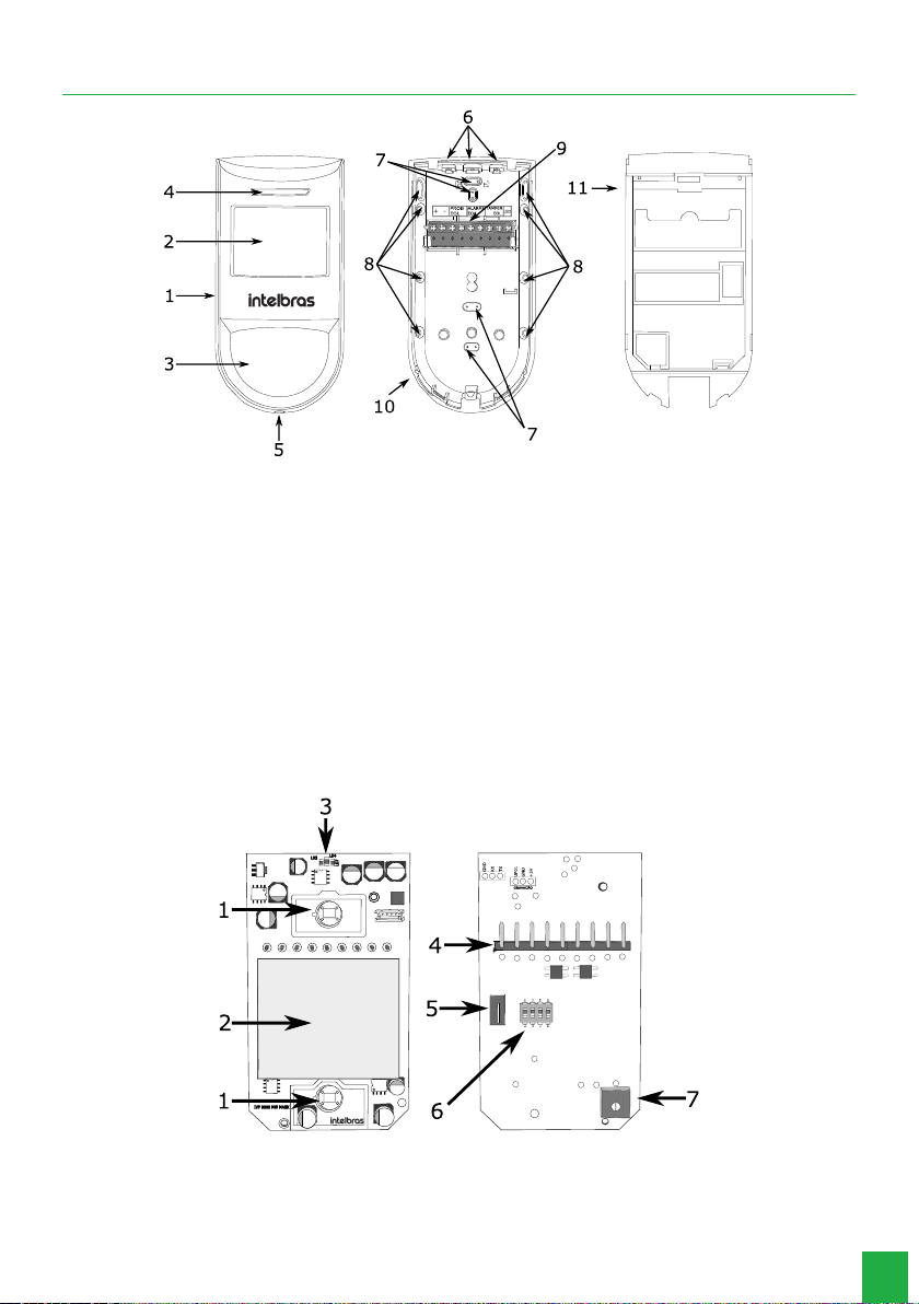
3. Product
1. Front cover
2. Flat lens
3. Hemispherical lens
4. LEDs
5. Closing screw
6. Wire passage seals
7. Seals for wall installation
8. Seals for corner installation
9. Connector
10. External base
11. Internal base
Board
12. Pyro sensor
13. Microwave module
14. LEDs
15. Connector
16. Tamper key
17. 4 position key
18. Trimpot microwave adjustment
8
4. Installation
» Before starting the installation, it is necessary to dene the height at which the sensor will be positioned, which can
vary from 2 to 2.4 m;
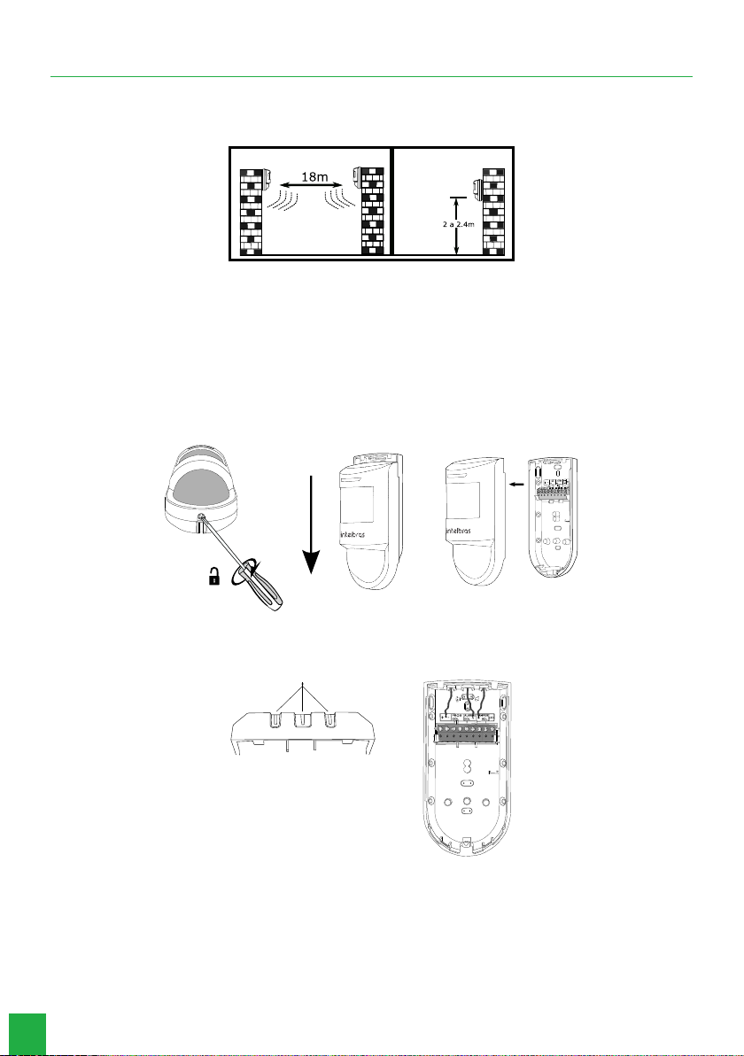
» Do not install sensors that have microwave technology close to each other, as there may be interference between them;
» The microwave sensitivity adjustment must be done according to each environment;
» For installation using the articulator, make sure that both the sensor and the bracket are securely xed in the installation
location to avoid changes in the product’s detection angle. Incorrect use of the articulator can change the sensor’s de-
tection area, creating blind spots and impairing operating efciency;
» If the sensor is installed at an angle, its detection range and PET function may be impaired in such a way as to nullify
the function.
To install the sensor, follow the procedure below:
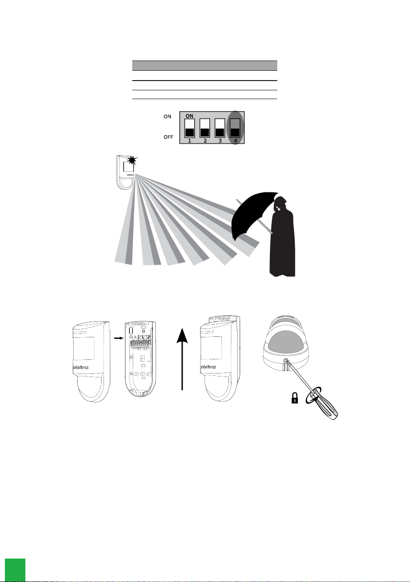
1. Unlock the back cover by partially loosening the screw and remove it by sliding the front cover down, as shown in the
picture.
2. Route the wiring through the cable passages located on the sensor back cover.
Note:
use a tool to drill the hole in the indicated location.
Cable passage
9
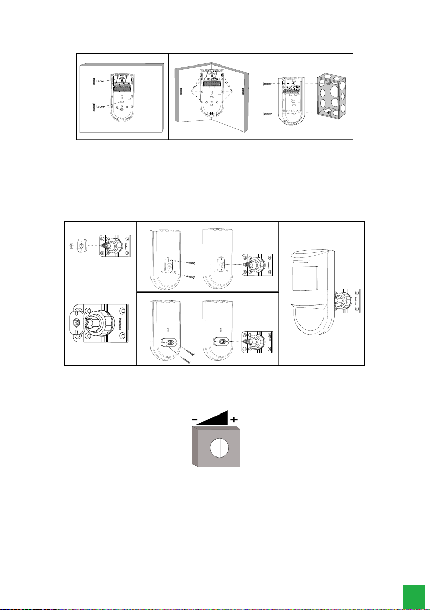
3. Connect the connecting cables to the sensor terminals and install in the place to be protected. For installation directly on
the wall, 4×2 box or in a corner of the wall, break the seals indicated for the holes in the rear xing cover.
Wall mounted Mounted in the corner of the wall 4x2 box installation
Lacre Lacre
4. Installation using the articulator.
Note: the articulator does not come with the product.
Attention: if the xing bracket is inclined to the ground, the characteristics of the
PET
function will change.
Use the xing holes located on the base to x the XSA 1000 articulator, for more information about the XSA 1000 articula-
tor, consult the user manual on the website: www.intelbras.com.br
The recommended screw for attaching articulators to the product is 3.5 × 9.5 mm.
XSA 1000 Position 1
Position 2
Mounted support
5. Perform the conguration on the sensor following the guidelines.
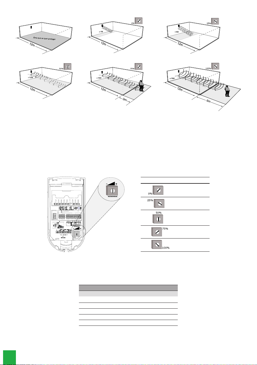
4.1. Microwave sensitivity adjustment
Microwave
The trimpot allows you to adjust the microwave’s sensitivity.Turning the trimpot clockwise increases the sensitivity
and consequently the distance at which the microwave is able to detect movement. Turning it counterclockwise
makes the microwave less sensitive.
Note: it is highly recommended to adjust the microwave sensitivity so that detection takes place only in the
environment where the sensor is installed. This technology is capable of detecting movement through a wall, for
example.
10
In gure 1 of the example above we have the area we want to protect. Figures 5 and 6 indicate that the trimpot
adjustment exceeded the limits of the environment to be protected. In this way the microwave will detect move-
ments outside the desired area.
To make it easier to adjust the microwave cover, adjust the trimpot counterclockwise (less sensitive) and walk in
the room you want to protect. Observe the sensor motion detection. If necessary, increase the sensitivity (clockwi-
se). Repeat this process until the sensor only protects the environment where it is installed.
The gure below shows a microwave channel detection range reference.
Factory default: 50%
Microwave range
Trimpot position Maximum distance
0% up to 1 meter
25% up to 5 meters
50% up to 12 meters
75% up to 15 meters
100% up to 18 meters
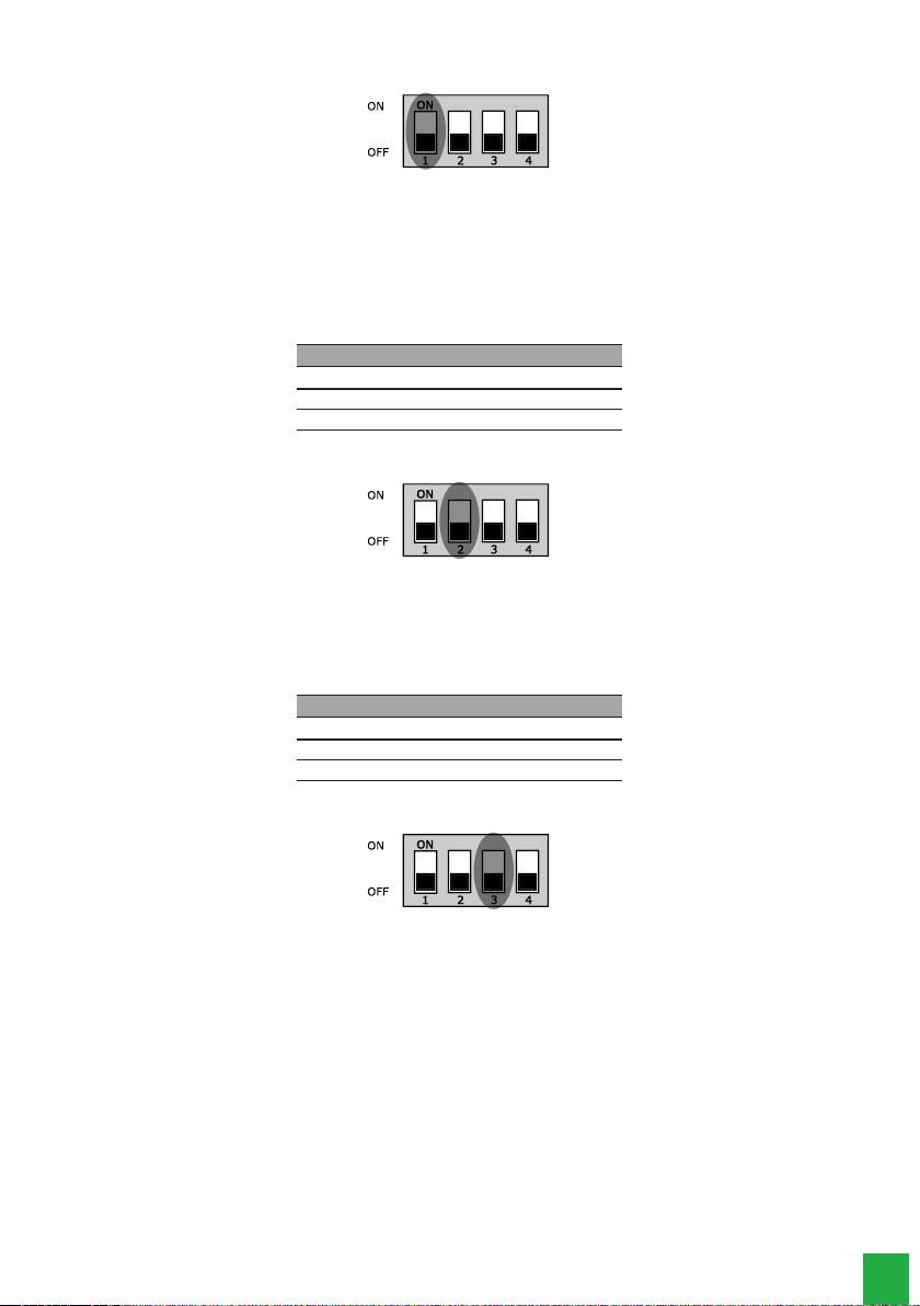
4.2. Operating mode settings
The key (S1) allows you to congure the sensor’s operating mode:
Key 1 – LED: works in conjunction with the LED input to control the visual indication of motion detection.
LED
Key 1 LED input LEDs
Condition Result
ON 12 Volts LEDs on
OFF 0 Volts LEDs on
ON 0 Volts LEDs off
OFF 12 Volts LEDs off
11
Factory default: LEDs on.
Key 2 – SENSITIVITY: controls the sensitivity of the two PIR channels to trigger the alarm.With the switch in the
ON position, the sensitivity is congured in order to avoid trips with little movement, that is, minimum sensitivity.
This setting is suitable for semi-open environments or environments with some interference that could cause
unwanted triggering.
With the key in the OFF position, the sensitivity remains with automatic adjustment and is controlled through an
algorithm that analyzes the conditions of temperature, light and movement of the environment.
SENS
Position Condition
ON Minimum sensitivity
OFF Automatic
Factory default: Automatic.
Key 3 – LOCAL: controls the sensor operation settings according to the installed environment.With the key in the
ON position, the sensor adjusts the operating mode and sensitivity for a semi-open environment.
Note: with this conguration the sensor does not detect camouage attempts.
With the key in the OFF position, the sensor adjusts its operating mode to an indoor environment..
Local
Position Condition
ON Semi-open
OFF Internal
Factory default: Internal.
12
Key 4 – ANTI-CAMOUFLAGE: the IVP 9000 MW is capable of detecting movements even if the individual uses
some material to camouage body temperature.With the key in the ON position, anti-tamper is enabled.With the
key in the OFF position, anti-tamper remains disabled.
Anti-camouage
Position Condition
ON Enabled
OFF Disabled
4.3. Process completion
Once the sensor is congured, close it by sliding up the front case on the back cover and tighten the screw.
13
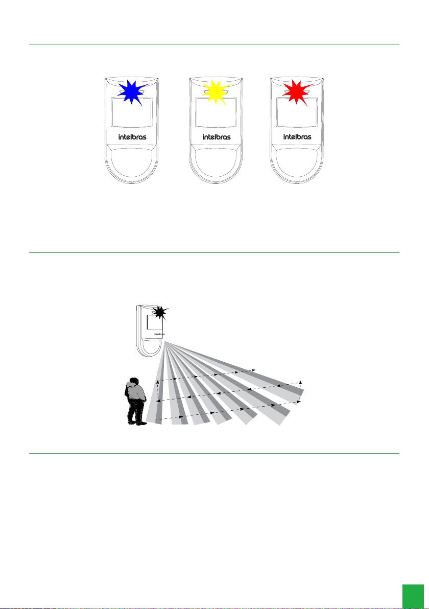
5. Operation
When turning on the sensor, the blue LED ashes for approximately 60 seconds.This time is necessary for the stabilization
of the circuits that make up the sensor.After this period, if they are enabled, the LEDs light up with each motion detection.
» Blue LED: alarm
» Yellow LED: Pir
» red LED: microwave
6. Test
Once installed and running, walk across the area to be protected, simulating a possible intrusion into the environment. See
if the sensor is able to detect your movements during the journey, through the LEDs. Adjust the microwave’s sensitivity to
the size of the room or reposition the sensor. Be sure to take all precautions and follow the installation recommendations
to obtain the best operating performance from the product.
7. Homologation
This equipment is not entitled to protection against harmful interference and may not cause interference to duly authorized
systems. This is a product approved by Anatel, the approval number can be found on the product label, for queries, visit the
website:
sistemas.anatel.gov.br/sch.

14
Warranty term
It is established that this warranty is granted upon the following conditions:
Client’s name:
Client’s signature:
Invoice number:
Date of purchase:
Model: Serial number:
Retailer:
1. All the parts, pieces and components of the product are guaranteed against possible manufacturing defects, which may
arise, for the term of 1 (one) year - this being 90 (ninety) days of legal guarantee and 9 (nine) months contractual war-
ranty –, counting from the date of purchase of the product by the Consumer, as appears in the product purchase bill of
sale, which is an integral part of this Term throughout the domestic territory. This contractual warranty includes the free
exchange of parts, pieces and components which have a manufacturing defect, including the expenses with labor used in
this repair. If there is no manufacturing defect, but defect(s) arising from misuse, the Consumer shall bear these expenses.
2. The installation of the product shall be executed in accordance with the Product Manual and/or Installation Guide. If your
product requires the installation and conguration by a qualied technician, seek a suitable specialized professional, the
costs of these services not being included in the product amount.
3. Having perceived the defect, the Consumer shall immediately contact the nearest Authorized Service which appears in
the report offered by the manufacturer – they are the only ones authorized to examine and remedy the defect during the
warranty term foreseen herein. If this is not respected, this warranty shall lose its validity, as it shall be characterized as
product infringement.
4. If the Consumer requests home service, it shall contact the nearest Authorized Service to inquire about the technical visit
rate. If it is necessary to remove the product, the ensuing expenses, such as those of transportation and insurance of the
taking and return of the product, shall be the Consumer’s responsibility.
5. The warranty shall lose its validity totally in the occurrence of any of the following cases: a) if the defect is not one of manu-
facture, but is caused by the Consumer or by third parties foreign to the manufacturer; b) if the damage to the product arises
from accidents, disasters, agents of nature (lightning, oods, landslides, etc.), humidity, voltage in the electrical network
(excess voltage caused by accidents or excessive uctuations in the network), installation/use in disagreement with the
user’s manual or arising from natural wear of the parts, pieces and components; c) if the product has undergone effects of a
chemical, electromagnetic, electrical or animal (insects, etc.) nature; d) if the serial number of the product has been falsied
or erased; e) if the appliance has been infringed.
6. This warranty does not cover loss of data; therefore, it is advisable that if it is the case of the product, the Consumer makes
a backup regularly of the data which appears in the product.
7. Intelbras is not responsible for the installation of this product, or for possible attempts at fraud and/or sabotage in its
products. Maintain the updates of the software and applications used up-to-date, if it is the case, as well as the network
protection required for defense against hackers. The equipment is guaranteed against defects in its usual conditions of use,
it being important to bear in mind that, as it is electronic equipment, it Is not free of fraud and scams which may interfere
with its correct functioning.
8. After its useful life, the product must be delivered to an authorized Intelbras service center or directly disposed of in an
environmentally appropriate manner to avoid environmental and health impacts. If you prefer, the battery, as well as other
unused Intelbras brand electronics, can be disposed of at any Green Eletron collection point (waste management facility
to which we are associated). If you have any questions about the reverse logistics process, please contact us at (48) 2106-
0006 or 0800 704 2767 (Monday to Friday 8am to 8pm and Saturdays 8am to 6pm) or via -mail support@intelbras.com.br.
These being the conditions of this complementary Warranty Term, Intelbras S/A reserves the right to alter the general,
technical and esthetic features of its products without prior notice.
All the images of this manual are illustrative.

01.22
Made in Brazil
Customer Support: (48) 2106 0006
Forum: forum.intelbras.com.br
Support via chat: chat.intelbras.com.br
Support via e-mail: suporte@intelbras.com.br
Customer Service: 0800 7042767
Where to buy? Who installs it? 0800 7245115
Produced by: Intelbras S/A – Indústria de Telecomunicação Eletrônica Brasileira
Rodovia BR 459, km 124, 1325 – Distrito Industrial – Santa Rita do Sapucaí/MG – 37540-000
CNPJ 82.901.000/0016-03 – www.intelbras.com.br | www.intelbras.com
Table of contents
Popular Accessories manuals by other brands


Benewake
Benewake TFmini-i product manual

Arista
Arista ALC-WM-DT-BT installation instructions

Alphacool
Alphacool NexXxoS CPX PHI-M01 instruction manual

Rice Lake
Rice Lake FlexWeigh System 101 Operation manual

Extreme Networks
Extreme Networks BlackDiamond 6816 Installation note

Omron
Omron ZX-LDA11 Operation manuals