2
www.phywe.com, © All rights reserved 12927-00 / 4119
3 FUNCTIONAL AND OPERATING ELEMENTS
3.1 Operating elements
The sensor has an on-button and two LEDs for indicating the
Bluetooth and battery status.
On-button
Press the on-button for more than 3 seconds to switch the
sensor on and off
Bluetooth-LED
Flashing red every 2 seconds
Flashing green every 2 seconds
Connected to the ter-
minal device
Flashing green every 4 seconds
Battery charge LED
Flashing red every 5 seconds
3.2 Functional elements
The face of the sensor has a BNC connector to which the
supplied ORP electrode can be connected.
4 NOTES ON OPERATION
This device fulfils all of the technical requirements that are
compiled in current EC guidelines. The characteristics of this
product qualify it for the CE mark.
This instrument is only to be put into operation under special-
ist supervision in a controlled electromagnetic environment in
research, educational and training facilities (schools, universi-
ties, institutes and laboratories).
The individual connecting leads are each not to be longer
than 2 m.
The instrument can be so influenced by electrostatic charges
and other electromagnetic phenomena (HF, bursts, indirect
lightning discharges) that it no longer works within the given
specifications. Carry out the following measures to reduce or
eliminate the effect of such disturbance: Ensure potential
equalization at the PC (especially with Laptops). Use screen-
ing. When a total failure of the instrument occurs, unplug it
and plug it back in again for a reset.
5 HANDLING
This section describes the start-up of the sensor and the re-
cording of measurement data. Please read this section thor-
oughly in order to avoid failures or operating errors.
5.1 Start-up
Switch the sensor on by pressing the on-button for more than
3 seconds. The Bluetooth LED lights up red. Start the soft-
ware and select the sensor.
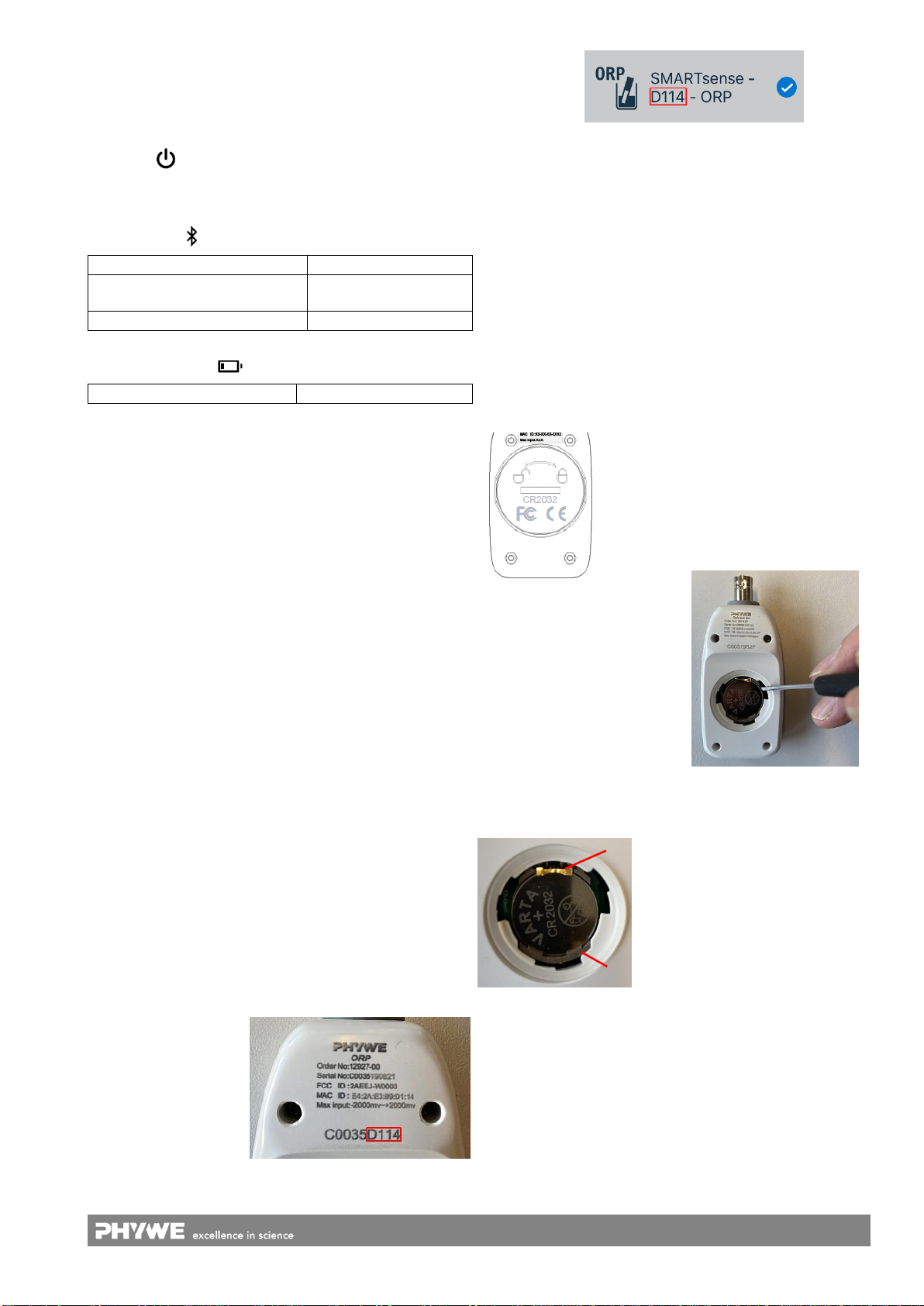
A 9-digit code is
printed on the back of
the sensor (Fig.2). The
last 4 digits of the code
are displayed as
sensor designation in
the software (Fig.3).
This enables an exact
assignment of the
sensors with the software.
Fig. 2
Fig. 3
After the sensor has been selected in the software, the LED
flashes green to indicate that the connection has been estab-
lished correctly.
If the sensor is switched on and not connected, it switches off
automatically after 5 minutes.
5.2 Recording measurement data
Connect the supplied ORP electrode to the BNC socket of
the sensor and immerse the electrode completely in the liquid
to be measured.
5.3 Replacing the battery
Remove the battery
Open the sensor by turning the screw
cap on the back of the sensor
counterclockwise e.g. with a coin.
Fig. 4
Carefully lift the battery out of
the socket, e.g. with the aid of
a small screwdriver or small
scissors. Insert the screw-
driver as shown in Fig. 5.
Fig.
Insert new battery
Slide the battery under the golden
metal nose (Fig.6-1). Make sure
that the battery is completely under
the metal nose and is pushed
completely to the upper edge.
Fig. 6
Press the battery into the socket by applying light pressure
on the opposite side.
The battery slides under the two plastic lugs (Fig. 6-2), which
can also be noticed by a short "click”


