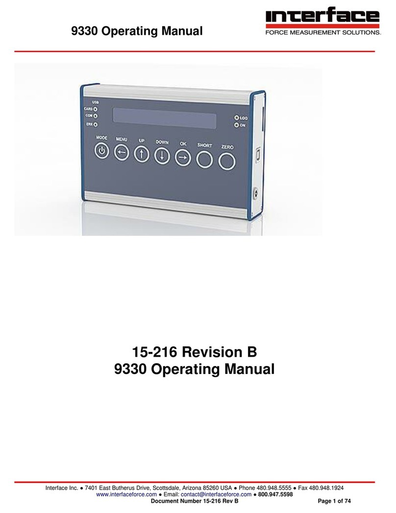
Interface BlueDAQ BX8 User manual

BX8 Operating Manual
Interface Inc. ● 7401 East Butherus Drive, Scottsdale, Arizona 85260 USA ● Phone 480.948.5555 ● Fax 480.948.1924
BX8 Operating Manual

BX8 Operating Manual
Interface Inc. ● 7401 East Butherus Drive, Scottsdale, Arizona 85260 USA ● Phone 480.948.5555 ● Fax 480.948.1924
Introduction
Eight full bridges provide mV/V input on 8 independent channels.
Communication interfaces such as USB port, EtherCAT, RS232 or CANbus are available.
Does not support RS-485.
The device has 8 configurable analog outputs (±10 V and 4-20 mA among others). UART
interface serves to control the measuring amplifier via the Raspberry PI (not for versions
with EtherCat).
There are three common types of the BX8.
oAS, HD15 and HD44. Each have their own Input/Output connectors.
8-channel measuring amplifier
8x input configurable
ofull, half, quarter bridges, 120- 350- 1000 Ohm, PT1000, ±10V
Outputs
o1x USB Port, 8x Analog output ±10V, 4-20mA configurable, 1x UART, alternatively
EtherCat, CANbus/CANopen
16x Digital in- and output
5x Galvanic isolation: analog-input, analog-output, digital-I/O, UART, USB
8x 48kS/s Simultaneous sampling
6-wire technology, bridge supply 2.5V, 5.0V, 8.75V configurable
Automatic configuration of analog and digital filters by specifying the data frequency
Additional Digital Filters IIR 4th order and FIR 14th order individually configurable
Step response of the filter configuration available (with PC software)
Resolution < 20 nV/V
Versions to connect 1-axis and 3- and 6-axis sensors
Autonomous calculation of 3 forces and moments of six-axis sensors Two operating hours
counters
Sensors with TEDS supported (readable and writable) Integration of a Raspberry PI in the
housing cover of the BX8-AS
Scope
To ensure the correct installation of BlueDAQ software.
To ensure the correct installation of the 6 Axis Load Cell to the BX8 Instrumentation to
communicate with BlueDAQ.
Abbreviations
DAQ
Data Acquisition
EXC
Excitation
SIG
Signal
PWR
Power

BX8 Operating Manual
Interface Inc. ● 7401 East Butherus Drive, Scottsdale, Arizona 85260 USA ● Phone 480.948.5555 ● Fax 480.948.1924
Description
The 8-channel measuring amplifier BX8 is characterized by particularly high resolution at data
frequencies of 1 Hz to 48000 Hz. The 8 channels are acquired simultaneously.
Versions
Type
Sensor Input
Signal-Output
BX8-HD15
8x SubD15HD
1xUSB, UART, Analog, Digital-I/O
BX8-HD15-EC
8x SubD15HD
1xUSB, EtherCat, Analog, Digital-I/O
BX8-HD15-CAN
8x SubD15HD
1xUSB, UART, CAN, Analog, Digital-
I/O
BX8-HD44
4x SubD44HD
1xUSB, UART, Analog, Digital-I/O
BX8-HD44-EC
4x SubD44HD
1xUSB, EtherCat, Analog, Digital-I/O
BX8-HD44-CAN
4x SubD44HD
1xUSB, UART, CAN, Analog, Digital-
I/O
BX8-AS
1x 24pol M16, screw
terminal
1xUSB, UART, Analog, Digital-I/O
BX8-AS-EC
1x 24pol M16, screw
terminal
1xUSB, EtherCat, Analog, Digital-I/O
BX8-AS-CAN
1x 24pol M16, screw
terminal
1xUSB, UART, CAN, Analog, Digital-
I/O
BX8-AS PI-3
1x 24pol M16, screw
terminal
like BX8-AS, but with Raspberry PI
Interfaces
Communication interfaces such as USB port or EtherCAT or CANbus are available. The
device has 8 configurable analog outputs (±10 V and 4-20 mA among others). UART interface
serves to control the measuring amplifier via the Raspberry PI (not for versions with EtherCat).
The interface protocol of USB and UART is identical and described in a separate
documentation. The fieldbus protocols EtherCAT and CANopen are standardized in the lower
protocol layers and the application layer is described in separate documents.

BX8 Operating Manual
Interface Inc. ● 7401 East Butherus Drive, Scottsdale, Arizona 85260 USA ● Phone 480.948.5555 ● Fax 480.948.1924
Software
The Windows programs BlueDAQ multichannel with graphical user interface and the console
terminal program BlueDAQ are suitable. A Windows function library (MEGSV8w32.dll) with
commented C header is available for self-programming users and a LabVIEW library with
wrapper VIs for this DLL for programming with LabVIEW ©.
Features
There are 8 analog inputs available. They are individually configurable as:
–Strain gauge input for full bridges in 4 and 6 wire technology or
–Strain gauge input for half bridges or
–Strain gauge input for quarter bridges 120 ohm, 350 ohm, 1 kOhm or
–Single-ended input ±10 V or
–Input for PT1000 temperature sensor
The strain gauge supply voltage can be switched between 8.75 V, 5.00 V and 2.5 V, assigned
to input sensitivities 2 mV/V, 3.5 mV/V or 7 mV/V.
Bridge supply voltage
Resulting input sensitivity
8.75 V
2 mV/V
5 V
3.5 mV/V
2.5 V
7 mV/V

BX8 Operating Manual
Interface Inc. ● 7401 East Butherus Drive, Scottsdale, Arizona 85260 USA ● Phone 480.948.5555 ● Fax 480.948.1924
Signal Flow

BX8 Operating Manual
Interface Inc. ● 7401 East Butherus Drive, Scottsdale, Arizona 85260 USA ● Phone 480.948.5555 ● Fax 480.948.1924
Galvanic isolation
The supply voltage UB+ / 0V is galvanically isolated from the modules for
✔analog input
✔analog output
UB+
Supply voltage 12...28V DC
UB-
Ground Supply voltage
GNDE
Ground analog-input
-Us
Negative bridge supply
GNDA
Ground analog-output
GNDD
Ground digital input / output
GNDU
Ground UART port („Raspberry PI Port“)
GNDR
Ground RS232 port (only BX8-AS)

BX8 Operating Manual
Interface Inc. ● 7401 East Butherus Drive, Scottsdale, Arizona 85260 USA ● Phone 480.948.5555 ● Fax 480.948.1924
Table of Contents
Dimensions...............................................................................................................................9
BX8-AS Diagram.............................................................................................................9
BX8-HD15 Diagram.......................................................................................................10
BX8-HD44 Diagram.......................................................................................................10
Specifications.........................................................................................................................11
Analog Input..................................................................................................................11
Digital Input / Digital Output...........................................................................................12
Analog Output...............................................................................................................12
Supply...........................................................................................................................12
Environmental Data.......................................................................................................12
Interfaces ......................................................................................................................13
Resolution of Strain Gage Input....................................................................................13
Noise Amplitude at Analog Output ................................................................................14
Digital Filters .................................................................................................................14
Finite Impulse Response Filter......................................................................................14
Infinite Impulse Response Filter....................................................................................15
Buttons and Indicators...................................................................................................16
Pin Configuration...........................................................................................................17
Additional Information...........................................................................................................35
LED Indicators...............................................................................................................35
LED-Display for Error Condition....................................................................................36
Function LED ................................................................................................................37
Status LED (Red)..........................................................................................................38
Digital Inputs and Outputs.............................................................................................39
Digital I/O Numbers.......................................................................................................39
Digital I/O Functions......................................................................................................40
Inverting Digital Inputs...................................................................................................43
Further Notes Digital I/O................................................................................................43
Master-Slave Frame Synchronization ...........................................................................44
Data Acquisition and Bandwidth....................................................................................44
Data Frames and Bandwidth.........................................................................................44

BX8 Operating Manual
Interface Inc. ● 7401 East Butherus Drive, Scottsdale, Arizona 85260 USA ● Phone 480.948.5555 ● Fax 480.948.1924
Installation of the 6 Axis to the BX8.....................................................................................51
BX8 Diagram.................................................................................................................51
BX8-AS Installation .......................................................................................................52
BX8-HD44 Installation...................................................................................................57
BX8-HD15 Installation...................................................................................................60
BlueDAQ Software Installation.............................................................................................63
COM Ports ..............................................................................................................................65
BlueDAQ - Adding a New Channel .......................................................................................67
Adding aSensor with a .DAT File.........................................................................................69
Adding aSensor Manually without a .DAT File...................................................................74
Distance Offset.......................................................................................................................81
Measurement and Recording................................................................................................82
BlueDAQ Menus.....................................................................................................................85
File ................................................................................................................................85
View ..............................................................................................................................90
Action............................................................................................................................93
Device...........................................................................................................................94
Channel.......................................................................................................................109
Sensor.........................................................................................................................112
Options........................................................................................................................118
Help.............................................................................................................................120

BX8 Operating Manual
Interface Inc. ● 7401 East Butherus Drive, Scottsdale, Arizona 85260 USA ● Phone 480.948.5555 ● Fax 480.948.1924
Dimensions
BX8-AS Dimension (Dimensions are in mm)

BX8 Operating Manual
Interface Inc. ● 7401 East Butherus Drive, Scottsdale, Arizona 85260 USA ● Phone 480.948.5555 ● Fax 480.948.1924
BX8-HD15 Dimension (Dimensions are in mm)
BX8-HD44 Dimension (Dimensions are in mm)

BX8 Operating Manual
Interface Inc. ● 7401 East Butherus Drive, Scottsdale, Arizona 85260 USA ● Phone 480.948.5555 ● Fax 480.948.1924
Specifications
Analog Input
Accuracy class
0.05%
Number of analog inputs
8
Strain gauge bridge input
Quarter, half, full bridge
Input impedance
> 20 MOhm (300pF)
Common mode rejection ratio DC
> 120 dB
Common mode rejection ratio AC 100Hz
> 100 dB
Strain gauge bridge completions
120 Ohm, 350 Ohm, 1 kOhm
Strain gauge bridge supply
2.50 V, 5.00 V, 8.75 Volt
Total current across all channels
200 mA
Max. current per channel at bridge supply
2.5V
40 mA (min. bridge resistance 62,5 Ohm)
Max. current per channel at bridge supply 5V
60 mA (min. bridge resistance 83,3 Ohm)
Max. current per channel at bridge supply
26 mA (min. bridge resistance 336,5 Ohm)
8.75V
Input sensitivities
7 mV/V, 3.5 mV/V, 2 mV/V
Input voltage, single-ended
±10 V
Input resistance
10 MOhm
Input for PT1000 sensor
-230 °C ... +1500 °C
Excitation voltage PT1000
1.25 V

BX8 Operating Manual
Interface Inc. ● 7401 East Butherus Drive, Scottsdale, Arizona 85260 USA ● Phone 480.948.5555 ● Fax 480.948.1924
Digital Input / Digital Output
Number of in-/ outputs
16
Output
TTL (0V 5V), push-pull
total current across all channels
140 mA
Max. load current per output
25 mA
Input
Max. input voltage
5.5 V
min. input voltage
-0.5 V
Resistance Pullup +5V
10 kOhm
Sampling period
40 msec
Analog Output
Number of analog outputs
8
Configuration of analog outputs
0-10V, ±10V, 0-5V, ±5V, 4-20mA
Supply
Supply voltage
12 V to 28 V
Power
< 12 W
Environmental Data
Operating temperature
0°C to 50 °C (32 to 122 Deg F)
Power
< 12 W

BX8 Operating Manual
Interface Inc. ● 7401 East Butherus Drive, Scottsdale, Arizona 85260 USA ● Phone 480.948.5555 ● Fax 480.948.1924
Interfaces
USB
2.0 Full speed
Devices class
Communication Device Class, HID (firmware
update only)
UART
Level 3.3V, galvanically isolated;
auxiliary voltage 24V DC, 2A
EtherCat
protocol: CoE device profile 404, Mailbox-
and
Buffered mode. Synchronization: Hardware-
Latching
CANbus
CANopen, device profile 404, 4x TxPDOs,
Resolution of Strain Gage Input
The resolution of measuring amplifier depends on the adjusted input sensitivity and the data
frequency. The input sensitivity is assigned to the bridge supply voltage: 8.75V with 2.0 mV/V,
5V with 3.5 mV/V, and 2.5V with 7 mV/V.
The excitation voltage with 8.75V is recommended only with sensors of minimum 1kOhm bridge
resistance and sufficient construction size. For miniature sensors under 500g weight the bridge
supply of 8.75V shall not be applied!
+Us
10 Hz
50 Hz
100 Hz
1 kHz
5 kHz
8 kHz
3.5 mV/V
5 V
2.0 105
1.2 105
8.0 104
2.5 104
1.0 104
8.0 103
2.0 mV/V
8.75 V
3.0 105
2.5 105
1.5 105
6.0 104
4.0 104
1.4 104
At a data frequency of 10 Hz the measuring range from 0 to +3.5 is quantized in 2.0 105steps.

BX8 Operating Manual
Interface Inc. ● 7401 East Butherus Drive, Scottsdale, Arizona 85260 USA ● Phone 480.948.5555 ● Fax 480.948.1924
The noise amplitude is 17.5 nV/V.
At a sensor with rated force of 10 N and rated output of 0.5 mV/V the noise amplitude is
Noise Amplitude at Analog Output
The noise amplitude at the analog output is approx. 25mV (peak values) or 10mV (RMS). It is
due to the galvanic isolation of the analog output. The frequency components of the noise
signal are predominantly at frequencies above 300 kHz and higher. These can be largely
attenuated by the use of oversampling with subsequent digital filtering (eg arithmetic
averaging) in the subsequent analog-digital conversion.
Digital Filters
The BX8 adjusts automatically the analog filter and the „decimating“digital input filter. The user
provides only the required number of measured values per second (data frequency), which is
send via USB-interface or made available to the field bus. Additionally there are two adjustable
digital filters: 1x FIR filter and 1x IIR filter. Each of these filter is individually adjustable for any
of the 8 input channels. In the measured data signal processing chain, the FIR filter is
processed first, followed by the IIR filter.
Finite Impulse Response Filter
The FIR filter is a low pass filter with which the filter order N and the cut-off frequency fg can be
set. The cut-off frequency is the frequency at which the signal is already attenuated by -3 db.
This corresponds to a factor of approx. 0.7. Frequencies lying above this will continue to be
attenuated.
The filter order determines the maximum and minimum adjustable cut-off frequency fg in terms
of the data rate Fa, and the steepness of the attenuation range. Higher orders have a steeper
slope, i.e. an increase in the signal frequency causes the attenuation to increase faster. The
so-called step response is slower at higher orders however, i.e. it always takes N+1 measured
values until the filter’s output value corresponds to the input value.

BX8 Operating Manual
Interface Inc. ● 7401 East Butherus Drive, Scottsdale, Arizona 85260 USA ● Phone 480.948.5555 ● Fax 480.948.1924
Order
fg/Fa min in Hz
fg/Fa min in Hz
14
0,05
0,190
12
0,06
0,225
10
0,07
0,270
8
0,09
0,340
6
0,12
0,350
4
0,18
0,410
Infinite Impulse Response Filter
The infinite Impulse Response Filter (IIR) of fourth order allows four different filter types:
1) Low pass filter: Sensor signals at low frequency (including DC size with f=0) pass through the
filter, signals at a higher frequency are attenuated.
2) High pass filter: Sensor signals at low frequency (including DC size with f=0) are
Attenuated, signals at a higher frequency pass through the filter. Note: Frequencies above half
of the measured data rate cannot be processed. The measuring amplifier includes an analog-
to-digital sampling system, which in itself acts as a low pass.
3) Band pass filter: Signals are allowed to pass through within a frequency range, signals which
are above or below this range are attenuated.
4) Band stop filter (‘Notch filter’): Signals are attenuated within a frequency range, signals which
are above or below this range are allowed to pass through.
The cut-off frequency can be configured for low and high pass filters. The cut-off frequency is
the frequency at which the signal is already attenuated by -3 db. This corresponds to a factor
of approx. 0.7. Frequencies lying above for low pass and lying below for high pass will
continue to be attenuated.
Two cut-off frequencies can be configured for band pass and band stop filters; the upper and
the lower. Attenuation by -3 dB also occurs here. The two cut-off frequencies may not be the
same. Signal frequencies lying between these are allowed to pass through for the band pass
filter, and are attenuated for the band stop filter.
The maximum (and also the minimum if need be) of each cut-off frequency is dependent on
the measured data rate. Cut-off frequencies can be set to (0.49 * measured data rate), i.e.
almost to half.

BX8 Operating Manual
Interface Inc. ● 7401 East Butherus Drive, Scottsdale, Arizona 85260 USA ● Phone 480.948.5555 ● Fax 480.948.1924
The filters can be individually configured for each channel and also switched on and off. The
configuration also remains the same for filters that have been switched off.
Buttons and Indicators
Power-button with LED function
Switch on and off the device (only BX8-HD)
Function LED
Mod-button with Led status
a) reset the status LED;
b) start the Firmware-updates, if during the
Power On activates
CHK button with Check LED
Sensor Test; by pressing the CHK button the
sensor signal for the unloaded condition is
emulated on the input of the measuring
amplifier; for sensors with calibration matrix
the
documented zero signals of the sensor are
Emulated on the inputs.
TA
„Tara“, Set-Zero“: trigger an automatic zero
adjustment for all outputs (analog and digital)
ECR-LED
EtherCat EC Run;

BX8 Operating Manual
Interface Inc. ● 7401 East Butherus Drive, Scottsdale, Arizona 85260 USA ● Phone 480.948.5555 ● Fax 480.948.1924
Pin Configuration
Connection of strain gauges, active sensors, TEDS. Activation of the bridge completion with
bridge from “HB” (12) to -UD (10).
No
Symbol
Description
1
TEDS
Transducer Electronic Data according to IEEE 1451.4
2
-Us
Negative bridge supply
3
+Us
Positive bridge supply
4
Q350
Quarter bridge completion 350 Ohm
5
+UD
Positive differential input
6
GNDE
Ground, analog input
7
-Uf
Negative sense line (6-wire connection only)
8
+Uf
Positive sense line (6-wire connection only)
9
Q120
Quarter bridge completion 120 Ohm
10
-UD
Negative differential input
11
Q1k
Quarter bridge completion 1000 Ohm
12
HB
Half bridge completion
13
VCCIO
Supply voltage for active sensors (optional)
14
Ue
Analog input voltage, single ended ±10V
15
GNDIO
Ground, supply voltage (optional)
Shield
PE
Earth (housing)

BX8 Operating Manual
Interface Inc. ● 7401 East Butherus Drive, Scottsdale, Arizona 85260 USA ● Phone 480.948.5555 ● Fax 480.948.1924
1/3 Channels 1,2,3, Sub-D HD 44
Pin
Signal
Description
Channel
Shield
PE
Earth (housing)
-
1
TEDS
Transducer Electronic Data according IEEE 1451.4
1
2
US-
Negative bridge supply
1
3
US+
Positive bridge supply
1
4
Q350
Quarter bridge completion 350Ohm
1
5
UD+
Positive differential input
1
6
GNDE
Ground, analog input
1
7
UF-
Negative sense line (6-wire connection only)
1
8
UF+
Positive sense line (6-wire connection only)
1
9
Q120
Quarter bridge completion 120Ohm
1
10
UD-
Negative differential input
1
11
Q1k
Quarter bridge completion 1000Ohm
1
12
HB
Half bridge completion
1
13
UE
Analog input voltage, single ended ±10V
1
14
GNDIO
Not equipped sep.galv. isol. (optional)
1
15
PE
Earth (housing)
-
16
TEDS
Transducer Electronic Data according IEEE 1451.4
2
17
US-
Negative bridge supply
2
18
US+
Positive bridge supply
2
19
Q350
Quarter bridge completion 350Ohm
2
20
UD+
Positive differential input
2
21
GNDE
Ground, analog input
2
22
UF-
Negative sense line (6-wire connection only)
2
23
UF+
Positive sense line (6-wire connection only)
2
24
Q120
Quarter bridge completion 120Ohm
2
25
UD-
Negative differential input
2
26
Q1k
Quarter bridge completion 1000Ohm
2
27
HB
Halt bridge completion
2
28
UE
Analog input voltage, single ended ±10V
2
29
GNDIO
Not equipped sep.galv.isol. (optional)
2

BX8 Operating Manual
Interface Inc. ● 7401 East Butherus Drive, Scottsdale, Arizona 85260 USA ● Phone 480.948.5555 ● Fax 480.948.1924
1/3 Channels 1,2,3, Sub-D HD 44
Pin
Signal
Description
Channel
30
VCCIO
Not equipped sep.galv.isol. (optional)
1,2,3
31
TEDS
Transducer Electronic Data acc. to IEEE 1451.4
3
32
US-
Negative bridge supply
3
33
US+
Positive bridge supply
3
34
Q350
Quarter bridge completion 350Ohm
3
35
UD+
Positive differential input
3
36
GNDE
Ground, analog input
3
37
UF-
Negative sense line (6-wire connection only)
3
38
UF+
Positive sense line (6-wire connection only)
3
39
Q120
Quarter bridge completion 120Ohm
3
40
UD-
Negative differential input
3
41
Q1k
Quarter bridge completion 1000Ohm
3
42
HB
Half bridge completion
3
43
UE
Analog input voltage, single ended ±10V
3
44
GNDIO
Not equipped sep.galv.isol. (optional)
3
The labeling on the front panel is 4/6 for connecting the channels 4 to 6.
4/6 Channels 4,5,6, Sub-D HD 44
Pin
Signal
Description
Channel
Shield
PE
Earth (housing)
-
1
TEDS
Transducer Electronic Data acc. to IEEE 1451.4
4
2
US-
Negative bridge supply
4
3
US+
Positive bridge supply
4
4
Q350
Quarter bridge completion 350Ohm
4
5
UD+
Positive differential input
4
6
GNDE
Ground, analog input
4
7
UF-
Negative sense line (6-wire connection only)
4
8
UF+
Positive sense line (6-wire connection only)
4
9
Q120
Quarter bridge completion 120Ohm
4
10
UD-
negative bridge supply
4
11
Q1k
Quarter bridge completion 1000Ohm
4
12
HB
Half bridge completion
4
13
UE
Analog input voltage, single ended ±10V
4
14
GNDIO
Not equipped sep.galv.isol. (optional)
4
15
PE
Earth (housing)
-
16
TEDS
Transducer Electronic Data acc. to IEEE 1451.4
5
17
US-
Negative bridge supply
5
18
US+
Positive bridge supply
5

BX8 Operating Manual
Interface Inc. ● 7401 East Butherus Drive, Scottsdale, Arizona 85260 USA ● Phone 480.948.5555 ● Fax 480.948.1924
4/6 Channels 4,5,6, Sub-D HD 44
Pin
Signal
Description
Channel
19
Q350
Quarter bridge completion 350Ohm
5
20
UD+
Positive differential input
5
21
GNDE
Ground, analog input
5
22
UF-
Negative sense line (6-wire connection only)
5
23
UF+
Positive sense line (6-wire connection only)
5
24
Q120
Quarter bridge completion 120Ohm
5
25
UD-
Negative differential input
5
26
Q1k
Quarter bridge completion 1000Ohm
5
27
HB
Half bridge completion
5
28
UE
Analog input voltage, single ended ±10V
5
29
GNDIO
Not equipped sep.galv.isol. (optional)
5
30
VCCIO
Not equipped sep.galv.isol. (optional)
4,5,6
31
TEDS
Transducer Electronic Data acc. to IEEE 1451.4
6
32
US-
Negative bridge supply
6
33
US+
Positive bridge supply
6
34
Q350
Quarter bridge completion 350Ohm
6
35
UD+
Positive differential input
6
36
GNDE
Ground, analog input
6
37
UF-
Negative sense line (6-wire connection only)
6
38
UF+
Positive sense line (6-wire connection only)
6
39
Q120
Quarter bridge completion 120Ohm
6
40
UD-
Negative differential input
6
41
Q1k
Quarter bridge completion 1000Ohm
6
42
HB
Half bridge completion
6
43
UE
Analog input voltage, single ended ±10V
6
44
GNDIO
Not equipped sep.galv.isol. (optional)
6
Other manuals for BlueDAQ BX8
2
This manual suits for next models
10
Table of contents
Other Interface Other manuals
Popular Other manuals by other brands

Moss Motors, Ltd.
Moss Motors, Ltd. Cobalt 910-850 installation instructions

KitchenAid
KitchenAid KFGR270 Installation instructions and use and care guide

Aquagarden
Aquagarden Marlin 300 instruction manual

Macnaught
Macnaught MAS1220-01 instruction manual

Hyundai
Hyundai ImageQuest P990+ Technical & service manual

Amprobe
Amprobe AM-510 user manual