AVL Looms TECHNICAL EDUCATION LOOM User manual

Loom Manual
Page 2
Loom Specifications
EQUIPMENT
Model Number
Compu-Jacq3G
Name
Technical Education Loom (TEL)
SAFETY
Certification
CE (EN 55011, EN 61000-6-1)
Emergency Stops
2 buttons; Activation by either button.
Activation stops rapier movement. Red lit
when activated; green light unlit. Pull
button to deactivate and return to normal
machine operation (red unlit, green lit).
Safe-Start
Jog mode start-up when rapier and drive
not at home
Interference Avoidance
Position sensors on rapier, beater and lift
system disallow unsafe shed and rapier
movement
Pinch Points
Steel and polycarbonate panels and
coverings
Electrical
Secured steel panels
Warnings
Pinch point, shock, hot surface and
emergency stop decals
FRAME
Type
TEL, black powder coat
Structure
Steel, 1in x 2in tubular
Gantry
Integrated with structure
Leveling
Adjustable feet, non-slip pads (6)
Foot Print
38.1in (96.8cm) W x 68.0in (172.7cm) D
Overall
60.0in (152.4cm) W x 109.0in (276.9cm)
D x 105.5in (268.0cm) H
OPERATING
ENVIRONMENT
Classification
Class B - Light Industrial, indoor
Temperature Range
50°F - 104°F (10°C - 40°C)
Humidity Range
10% - 90 % Relative Humidity
Ventilation/Cooling
None required
FLOOR BRACING
Type
Flat Concrete, 2,500 PSI (176 KG/cm)
min. compressive strength
Concrete Insert for
Mounting Bolt
1 per side, HILTI drop in expansion
anchor (or comparable)
Bolt for seismic bracing
bracket
1 per side, ½”-13 x 1” grade 5 hex bolt
(or comparable grade metric hex bolt)

Loom Manual
Page 3
Loom Specifications (continued)
ELECTRICAL
INPUT
Connection
2 –15ft (4.6m) electrical cords, 3-Wire (Live,
Neutral, Ground), direct wire to plant
Protective Earthing
Through electrical cord ground wire
Supply Voltage
Range
2 - 220-240 VAC, single phase, 50-60 Hz
Maximum Current
Draw
Line 1 (upper): 18.3A
Line 2 (lower): 10.7A
Current Rating at
On/Off Breakers
Line 1 (upper): 20.0A
Line 2 (lower): 15.0A
Circuit Protection
UPS recommended
EXTERNAL
ELECTRICAL
CIRCUITS
Power Input Cord
Circuit Rating
12AWG, 25A, 300V max
Motor Circuit Rating
22 AWG, 5A, 300V max
Cloth Advance
Sensor Circuit
Rating
22 AWG, 300V max
Beater Position
Sensor Circuit
Rating
26 AWG, 500V max
Brake Circuit Rating
20 AWG, 300V max
DATA INPUT
Connection
USB 2.0
Data Cable
10ft. (3m) USB 2.0 Male A / Male B
PC (customer
supplied)
Windows XP –8; USB port; Mouse
Control Software
JacqPoint ver. 2.0
NOISE
Maximum Sound
Power Level
Produced
69db
Equipment Lamp/Light Condition Indicators
COLOR
MEANING
APPLICATION
EXPLANATION
RED
Emergency
Emergency stop. Initiation
of emergency function
Actuate in case of hazardous
condition or emergency
GREEN
Normal
Tool functioning properly
Actuated when power
applied, breakers on and
emergency stops deactivated

Loom Manual
Page 4
Loom Specifications (continued)
PATTERN
Mechanism
AVL 3rd generation Jacquard, Jacq3G™
Jacquard Configuration
10 modules W x 120 hooks D (1,199 total hooks)
Density
150 EPI (cast out for lower density)
Shedding Mechanism
AVL E-Lift™ (stepper motor)
Heddle
Inserted eye, nickel plated, cinch-top,
400mm x 1080R
Spring attachment, molded plastic
Electronics
Compu-Jacq™ control, USB 2.0 input
Jacq3G special features
Easy-Access module support frame
Positive airflow minimizes fiber contamination
Control computer
Customer-supplied, MS Windows XP-10
Control Software
JacqPoint ver. 2.0
Computer table
12in (30.5cm) W x 36in (91.4cm) D x 36in
(91.4cm) H
Engineered wood, black melamine wrapped
Steel, black powder coated
WEFT
Delivery
Single color rigid rapier (stepper motor)
Storage
Spool, 4.0in (10.2cm) Dia. x 4.0in (10.2cm) W
Tension
Single yarn tensioner, adjustable
Spool Control
Drag, adjustable
WARP
Delivery
Tensioned Creel (customer supplied)
Input Guide
Rollers (2), controls warp height
Open top raddle, controls warp width
Output Guide
Fixed bars (2), controls warp height
Advance
Automatic electronically programmable or
manual, 0.001-5 PPI
Output clamping
Adjustable clamp with SmoothGrip™ surface
Fabric removal
Adjustable clamp with SmoothGrip™ surface
Fabric storage table
Integrated cloth clamp table, 9.9in (28.1cm) W x
35.5in (90.2cm) D
Engineered wood, black melamine wrapped Steel,
black powder coated
BEATER
Type
Bottom swing, rigid aluminum construction
Pivot
Roller ball bearing
Reed
12 DPI x 8in W x 5in H
Controls
SHED and RAPIER activation buttons

Loom Manual
Page 5
Tools and Spare Parts
P/N
DESCRIPTION
INCLUDED
WITH LOOM
SLEY-10
Heddle threading hook
1
SLEY-S
Reed sleying hook
1
N/A
Weft tensioner threader
1
ALEN-1/4
¼” Allen wrench
1
ALEN-26566
1/8” Allen wrench
1
ALEN-26570
5/32” Allen wrench
1
ALEN-26572
3/16” Allen wrench
1
ALEN-2MM
2mm Allen wrench
1
ALEN-82615
9/64” Allen wrench
1
N/A
Drive programming cable, STAC6-SI
1
N/A
Seismic bracket (set of two with mounting hardware)
1
J3G-MOD-M019
Jacq3G hook
20
HDL-400x1080R-LANCIA
Jacquard Heddle,1080R inserted eye, Lancia top
20
SPR-SPAM-65/90
Spring 65/90, D0.025, 11.0" Jacq
20
SOL-RG-03UA-B01
Solenoid, Jacq3G assembly
10
J3G-MOD-CBL-D001
Drive cable
5
TEL-COMB-25A,
Q2-09-MS500FT,
Q2-F3X-1/16-01-MS100FT,
HH3SS
36” comber cord with HH3SS hook assembly
10

Loom Manual
Page 6
Overview
This manual provides technical specifications, feature reviews and notes on operation and
maintenance for Technical Education Loom (TEL). The loom was developed for the purpose of
training new technicians for production of three dimensional, non-conductive technical fiber
fabrics and parts.
Intended Use
The TEL provides a training platform that allows the student to participate in the weaving
process, seeing and directly experiencing the effects of pattern, interlacement, beat up and fabric
advancement. Being a manual loom, all processes are slowed sufficiently for easy observation,
and thus optimal understanding.
The primary technologies incorporated into the loom are:
Electronic Jacquard pattern selection
Electronic shed lift
Electronic rapier weft placement
Electronic fabric advancement
The TEL is designed for use with non-conductive yarns. Use of conductive yarn or fiber in or
around the loom could damage the equipment.
In normal operation, all secured panels must stay closed and secured. Only qualified AVL
personnel should open panels.

Loom Manual
Page 7
Before Getting Started
Please read the entire manual before using the loom.
Warnings:
WARNING: EQUIPMENT SHOULD ONLY BE USED FOR TEXTILE MANUFACTURING.
IF THE EQUIPMENT IS USED IN A MANNER NOT SPECIFIED BY THE
MANUFACTURER, THE PROTECTION PROVIDED BY THE EQUIPMENT MAY BE
IMPAIRED.
WARNING: ELECTRICAL SHOCK HAZARD. DO NOT TAMPER WITH ELECTRICAL
WIRES OR OPERATE THE LOOM WITH SAFETY PANELS OPENED OR REMOVED.
WARNING: PINCH, CRUSH, AND FINGER CUT-OFF HAZARDS. DO NOT OPERATE
THE LOOM WITH SAFETY PANELS OPENED OR REMOVED. DO NOT PLACE HANDS
IN MOVING MECHANISMS OR SCISSORS.

Loom Manual
Page 8
WARNING: HOT SURFACE. DO NOT TOUCH
ATTENTION: EMERGENCY STOP. PRESS TO STOP RAPIER MOVEMENT. PULL TO
RETURN TO NORMAL OPERATION.

Loom Manual
Page 9
WARNING: EQUIPMENT PANELS ARE AWKWARD AND HEAVY. TO AVOID MUSCLE
STRAIN OR INJURY, USE PROPER LIFTING TECHNIQUES AND A HELPER.
WARNING: SECURED PANELS ARE TO BE REMOVED ONLY BY AN AVL
TECHNICAL REPRESENTATIVE.
WARNING: DO NOT POSITION EQUIPMENT IN A WAY TO BLOCK OR IMPEDE
ACCESS TO DISCONNECTING DEVICES, EMERGENCY STOPS, OR ON/OFF BREAKER
SWITCHES
WARNING: USE OF CONDUCTIVE FIBER OR YARN ON OR AROUND THIS
EQUIPMENT WILL VOID WARRANTY AND MAY DAMAGE EQUIPMENT.
WARNING: THIS EQUIPMENT IS CLASSIFIED FOR LIGHT INDUSTRIAL
ENVIRONMENT ONLY. OPERATION OF HIGH-CURRENT DRAW EQUIPMENT (EX.
MIG WELDER) ON THE SAME ELECTRICAL CIRCUITS MAY CAUSE EQUIPMENT
FAILURE.

Loom Manual
Page 10
Safety Features:
The loom contains several safety features designed to avoid injury and equipment damage.
These include:
1) Electrical lockout switches stop electricity flow to loom.
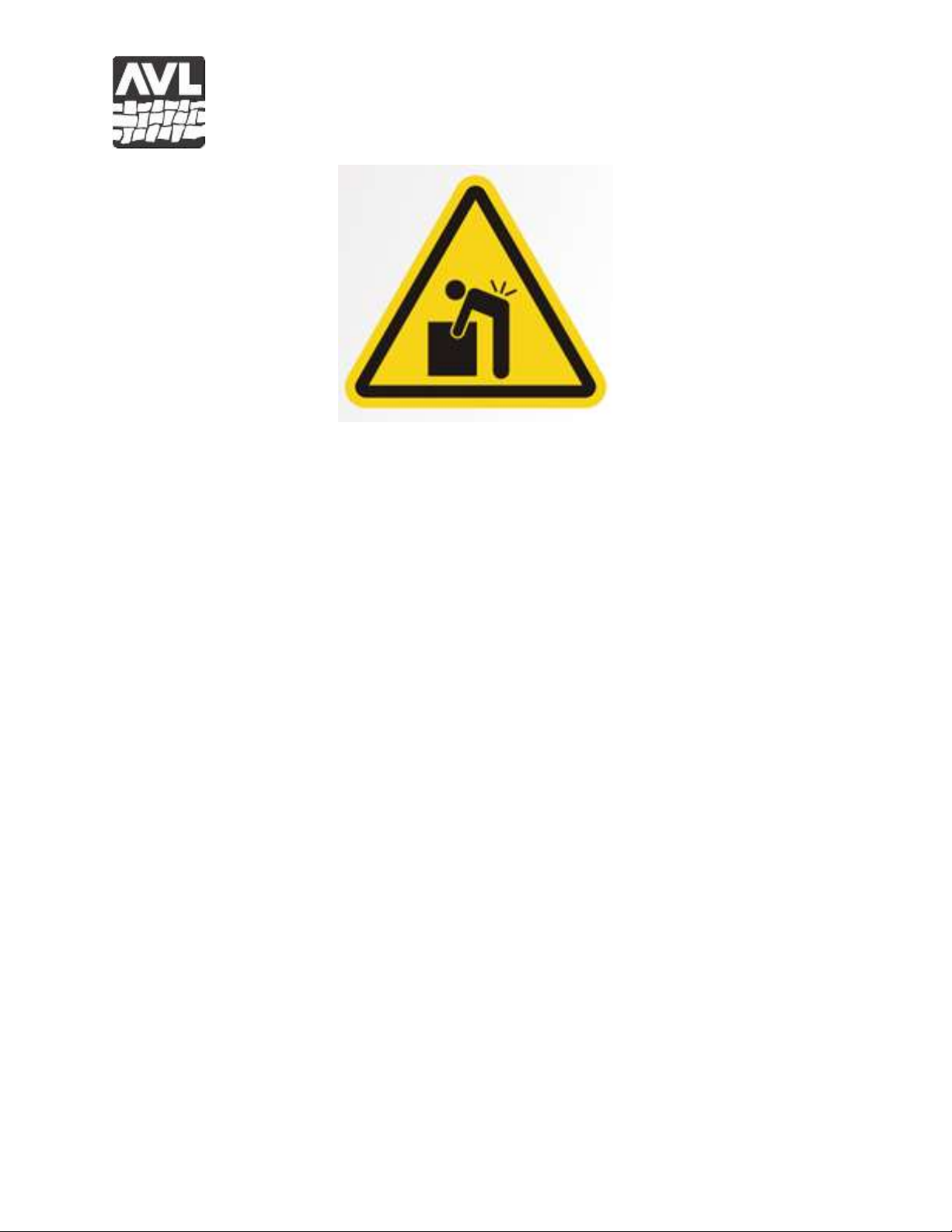
2) Safety labels draw attention to danger areas. Do not reach under a panel while the loom is
powered.
3) Green light prominently displays that the loom is powered and On/Off Breakers are
switched on. Light extinguishes when power is removed, Breakers are off, or when
either or both emergency stop buttons are pressed.
4) Panel secured with fasteners. Behind the main panels are high voltage and the more
extreme pinch dangers.
5) Panel hinges allow for opening and access without removal of large, heavy equipment
panels.
6) Covers and shielding separate weaver from moving components where pinch hazards
exist. Do not reach under a covers and shielding while the loom is operating.
7) Emergency stop button cuts power to the rapier motor. Activation stops the rapier from
moving avoiding potential personal and equipment damage. The depressed emergency
stop button lights red to notify user that the loom requires attention. The Green Power-
On Lamp is deactivate when red light is on. Pull out the emergency stop button once the
danger has been addressed and to resume loom normal operation.
8) Beater and drive sensors disallow rapier activation unless beater is in rear-most position
and drive is in open shed position.
9) Slow start programming is provided to enable clearing of the equipment after emergency
or accidental shut down. Slow start allows small, incremental step movements of the E-
Lift and rapier by pressing the respective beater button until home positions are reached.
Shed lift home is the open shed position. Rapier home is the fully retracted position.

Loom Manual
Page 11
Installation and Commissioning
Personnel:
Installation and commissioning shall be performed by authorized AVL Looms personnel only.
Location:
Equipment must be installed on a flat concrete floor. The concrete floor must be rated to support
a minimum of 2,500 PSI compressive strength.
A 5ft (1.5m) clearance should be provided on each side of loom. Space considerations for the
customer-supplied creel will include the at least 5ft (1.5m) of open space between the back of the
loom and the creel, plus the creel length.
Connection to Plant Electrical:
Connection of the equipment to electricity shall be performed by a qualified electrician only. The
plant circuit must be rated for 208-240 VAC, 50-60Hz, single phase with line 1 at 20A and line 2
at 15A. The electrical cord provided may be either hardwired into the plant electricity or wired to
a suitably rated plug for a corresponding outlet.
Seismic Concerns:
Where seismic concerns exist, equipment should be installed with supplied brackets and
hardware. Use HILTI drop in expansion anchors inserted into the concrete floor. Use HILTI
instructions for concrete preparation and anchor installation. Use Grade 5 ½”-13x1” Fastener
Bolts (or equivalent metric hardware).
Loom Square and Level
The loom must be squared and leveled during installation. Squaring entails measuring
diagonally, front to back, in each direction. If the measurements do not match within one-
sixteenth of an inch, loom hardware is loosened and the frame is racked until the measurements
match, then the frame hardware is tightened. The loom is provided with six adjustable height feet
for leveling. For side to side leveling, place a level on a horizontal crossmember and adjust the
feet. For front to back leveling, place a level on a horizontal sideframe member and adjust the
feet. Feet adjustment may require slight jacking of the frame.

Loom Manual
Page 12
Operation
Perspective:
All discussion in this manual is presented from the weaving position at the front of the loom.
The left side of the loom is to the weaver’s left. The front of the loom is where the weaver
stands.
Loom Startup/Shutdown:
Startup
1. Ensure that the rapier path is clear. Flip to the ON position (I) the two power switches
located on the left side panel of the control system on top of the loom.
220-240 VAC
CORDS
USB
ON/OFF BREAKERS

Loom Manual
Page 13
1. Jog the rapier home by pressing and holding the right button (RAPIER) on the beater
until the rapier head reaches its home position and stops moving within the housing on
the right side of the loom.
2. Jog the E-Lift home by pressing and holding the left button (SHED) on the beater until
the heddles reach their lowest position and stop moving.
3. For JacqPoint loom control, refer to Loom Control Steps in the Personal Computer
and Software section of this manual.
Shutdown
1. With the rapier at home, select Null Pick in JacqPoint Loom Control window. Select
the left beater button to activate the null pick.
2. Exit the Loom Control windows.
3. Flip to the OFF position (O) the two power switches located on the left side panel of the
control system on top of the loom.
Weaving:
Weaving is designed to be simple and easy to observe using the following steps:
1) The user stands at the front of the loom, on either side of the output table with one hand
on the beater.
2) To open a shed, the user selects the left button (SHED) on the beater to activate the E-
Lift. The E-Lift will momentarily move to center shed to allow hook selection, and then
open the shed for weft insertion.
3) Once the shed is achieved, the user presses the right button (RAPIER) to activate the
rapier. The rapier runs across the warp, grabs the weft yarn, activates the scissors and
returns to its starting position.
BEATER
BUTTONS

Loom Manual
Page 14
4) The user pulls the beater forward to beat the weft yarn into the shed.
5) Using the left button, the user changes
shed, and then returns the beater to its
rear position.
6) The user repeats the process starting at
step 3.
NOTES:
a) At first weft insertion, the user must pre-
position the weft for the rapier. To
accomplish this:
1. The beater is pulled forward to
the stops.
2. The weft yarn is pulled from the tensioner, through the open scissor and held the
end at the left side of the reed holder, which will be the fell line location. This
positions the weft yarn to be grabbed by the rapier.
3. The beater is pushed back, then the rapier is activated.
b) Selecting and holding the left (SHED)
button on the beater for a count of 15
seconds will switch shed modes. The two
shed modes are:
1. Double shed (normal operation)
2. Single step shed
(maintenance/diagnostics); Use
single step when lubricating the
hooks and when diagnosing hook
selection issues.
c) The loom controller will automatically shut off all solenoids after fifteen seconds of
activation, which may occur in single step mode at center shed. In addition, the solenoids
are automatically inactivated at open shed.

Loom Manual
Page 15
Weaving Settings:
Cloth Advance Introduction
The cloth advance system is designed to
achieve three goals:
1) Smooth, even fabric advancement
2) Managed warp/fabric tension
3) Consistent fell-line position
Its capabilities include: manual and
automatic operation, wide range of distance
and speed settings, advance/no advance on a
per pick basis, and high strength drive for
advancing up to 750 lbs. of warp force.
The programmable automatic cloth advance consists of three primary components:
1) Linear drive coupled electronic stepper motor
2) Man-Machine Interface (MMI)
3) JacqPoint setting

Loom Manual
Page 16
Cloth Advance Operation
The electronic stepper motor and drive are controlled through the MMI, JacqPoint selection
and embedded limit sensors.
MMI and MMI Menu Button
1) To access the MMI, press the MMI Menu button to the left of the MMI. The home screen
will change to the first selection menu.
2) Select the 4 key on the MMI to access
‘Parameters’. Parameters define the distance
and speed of linear drive movement for
automatic cloth advance, manual advance and
retreat (1:ADV and 2:RET). The distance
range can be set between 0.0001 and 5 inches.
The speed can be set between 1 and 20
revolutions/second. Press enter after each
parameter selection. To determine your desired
distance simply invert your desired picks per
inch. The speed setting will require
experimentation to determine the optimal
setting for your weaving.

Loom Manual
Page 17
3) Select 1 ‘Adv’ to move the cloth clamp one pick’s distance away from the beater.
4) Select 2 ‘Ret’ to move the cloth clamp one pick’s distance towards from the beater.
5) Select 3 ‘Jog’ for faster movement of the cloth clamp. The Jog selection input screen will
be displayed on the MMI.
a. Press the key to advance the
cloth clamp (move away the
beater). Press the key again to stop
movement, or allow the linear drive to
reach its end limit sensor.
b. Press the key to retreat the cloth
clamp (move towards the beater).
Press the key again to stop movement,
or allow the linear drive to reach its
home limit sensor.
6) Select 5 ‘Exit’ to exit the MMI menu and weave in automatic cloth advance mode.
7) JacqPoint selection of pick by pick advance activation is done by selecting/de-selecting
hook #1200. When the hook is selected for activation on a pick, the linear drive will
advance the cloth clamp by the distance and speed selected in the MMI Parameters menu.
Parameters Menus

Loom Manual
Page 18
NOTES:
When either the home or end limit sensor switch is reached, the linear drive will no
longer move the cloth clamp. However, the weaver may continue weaving (opening
sheds and using the rapier to lay-in the weft).
When the end limit sensor is reached, the MMI screen notifies the weaver of the limit.
Weaver must manually move the cloth clamp back to the home position for tie-on.
Rapier Extended Position:
A stationary rubbing block and spring-loaded dog are located near the extended position to
squeeze open the rapier head gripper in order to capture the weft yarn. In setting rubbing
block/dog positions, first adjust the block such that the head very lightly rest on it. Then,
adjust the dog to open the gripper sufficiently to allow the weft yarn slide into the gripper.
The head should move past the dog, thus fully gripping the weft yarn, before intersecting
with the scissor bearing.
RUBBING BLOCK
DOG

Loom Manual
Page 19
Rapier Home Position:
Rapier position settings are set at the factory.
Rapier home position is in the fully retracted position. The rapier home position sensor lights
when not triggered. With the rapier fully retracted, position the sensor right at the point
where the sensor light turns off.
Two stationary rubbing blocks, one each above and below where the head sits when in home
position, are positioned to squeeze open the gripper for releasing the weft yarn. In setting
rubbing block positions, first adjust the lower block such that the head very lightly rest on it.
Then, adjust the upper rubbing block to open the gripper just enough to release the weft yarn
just before the rapier reaches home.
Rapier Gripper Tension:
Gripper tension is set by loosening the lock screw on the front side of the rapier head,
tightening or loosening the bolt on top of the rapier head, and then tightening the lock screw.
The gripper tension should be set

Loom Manual
Page 20
Rapier System:
The rapier position is set at installation. The critical settings for the rapier are
Level travel
Consistent 1/8 inch spacing from the reed as head moves across
Rapier nose point just above center line
With the loom unpowered, manual move the rapier for measuring these settings. Adjust
position with the system hardware.
Scissor Position:
The scissor is activated when the rapier head moves onto the scissor head rubbing block.
Scissor positioning is set at the factory. Adjusting the scissor position requires moving the
bearing in line with the rapier head. The height of the bearing defines the amount of arc in
the scissor movement, where a lower setting equates with more arc.
This manual suits for next models
1
Table of contents
Other AVL Looms Other manuals

AVL Looms
AVL Looms Dobby User manual

AVL Looms
AVL Looms K Series User manual

AVL Looms
AVL Looms Jacq3G User manual

AVL Looms
AVL Looms A Series User manual

AVL Looms
AVL Looms Rug Loom User manual

AVL Looms
AVL Looms Compu-Dobby V User manual

AVL Looms
AVL Looms HOME LOOM with Compu-Dobby III Quick reference guide
Popular Other manuals by other brands

Eaton
Eaton EAFR-110 Series user manual

Audio Technica
Audio Technica ATH-SPORT7TW user manual

Rioned
Rioned UNICOM user manual

Bose
Bose QUIETCOMFORT 35 owner's guide

Whelen Engineering Company
Whelen Engineering Company PAR-32 LINZ6 installation guide

Cabletron Systems
Cabletron Systems IRBM supplementary guide