Interlink electronics FSR Quick setup guide

www.interlinkelectronics.com
Force Sensing Linear Potentiometer (FSLP)
Integration Guide
Interlink Electronics
FSR® Force Sensing Resistors®
Force Sensing Linear Potentiometer (FSLP)
Integration Guide
Document P/N: 94-00022 Rev. C
Interlink Electronics and the six dot logo are registered trademarks of Interlink Electronics, Inc.

www.interlinkelectronics.com
Force Sensing Linear Potentiometer (FSLP)
Integration Guide
Table of Contents
1.0 Introduction.................................................................................................................... 1
2.0 Scope................................................................................................................................1
3.0 Theory of Operation .................................................................................................... 2
4.0 Mounting and Connection ......................................................................................... 5
4.1 Mounting............................................................................................................. 5
4.2 FSLP Types........................................................................................................ 5
4.3 Crimp Terminal Connections (10cm and derivatives only) ................................ 7
4.4 FFC Connection Method .................................................................................... 8
5.0 Measurement Techniques and Algorithms.......................................................... 9
5.1 Measuring Position........................................................................................... 10
5.2 Measuring Pressure ......................................................................................... 10
6.0 Actuator......................................................................................................................... 12
7.0 Orderable Part Numbers.......................................................................................... 12
8.0 Intellectual Property & Other Legal Matters.................................................... 12
9.0 Contact Interlink Electronics ................................................................................ 13

www.interlinkelectronics.com
1
Force Sensing Linear Potentiometer (FSLP)
Integration Guide
1.0 Introduction
The Interlink Electronics Standard Force Sensing Linear Potentiometer (FSLP) is a linear position
sensor for menu navigation and control. It functions as a linear potentiometer with the ability to
detect a user's force for variable rate scrolling and a more intuitive user experience. The FSLP is
an easy to integrate, high resolution, ultra low-power package ideal for media players, mobile
phones, control panels, medical instruments and home entertainment devices. Measurement is
simple enough that it can be accomplished directly with the device's host processor without the
need for a dedicated microprocessor.
The purpose of this document is to guide users through the successful integration of the Interlink
Electronics FSLP.
2.0 Scope
This Integration Guide provides the OEM integrator with all of the necessary technical information
to successfully integrate the FSLP into products such as:
Personal media players
Mobile phones
Control panels
Medical instruments
Home entertainment devices
Sensor part number is detailed in section 7.

www.interlinkelectronics.com
2
Force Sensing Linear Potentiometer (FSLP)
Integration Guide
3.0 Theory of Operation
The most basic Force Sensing Resistor (FSR) consists of two membranes separated by a thin air
gap. The air gap is maintained by a spacer around the edges and by the rigidity of the two
membranes. One of the membranes has two sets of fingers which are interdigitated and
electrically distinct; each set connects to one trace on the tail. The other membrane is coated with
FSR ink. When the two layers are pressed together, the FSR ink shorts the two traces together
with a resistance that depends on applied force.
Figure 1: Exploded view of a standard single-zone FSR

www.interlinkelectronics.com
3
Force Sensing Linear Potentiometer (FSLP)
Integration Guide
Like the basic single-zone FSR, the Interlink Electronics FSLP has an FSR ink layer and a
conductor substrate layer separated by an adhesive spacer. The FSLP’s conductor layer
however, is not simply a set of interdigitated silver fingers; it consists of two drive lines connected
to either end of a printed fixed resistor and a sense line. Silver fingers orthogonally protrude along
the entire length of the fixed resistor. These silver fingers are interdigitated with the sense line.
When the FSR ink and conductor membranes are pressed together, the sense line is shorted to a
point along the fixed resistor through the orthogonally protruding fingers. The resistance from
either drive line to the touch point is proportional to the location of the touch along the length of
the fixed resistor.
Figure 2: Exploded view of the FSLP.
www.interlinkelectronics.com
4
Force Sensing Linear Potentiometer (FSLP)
Integration Guide
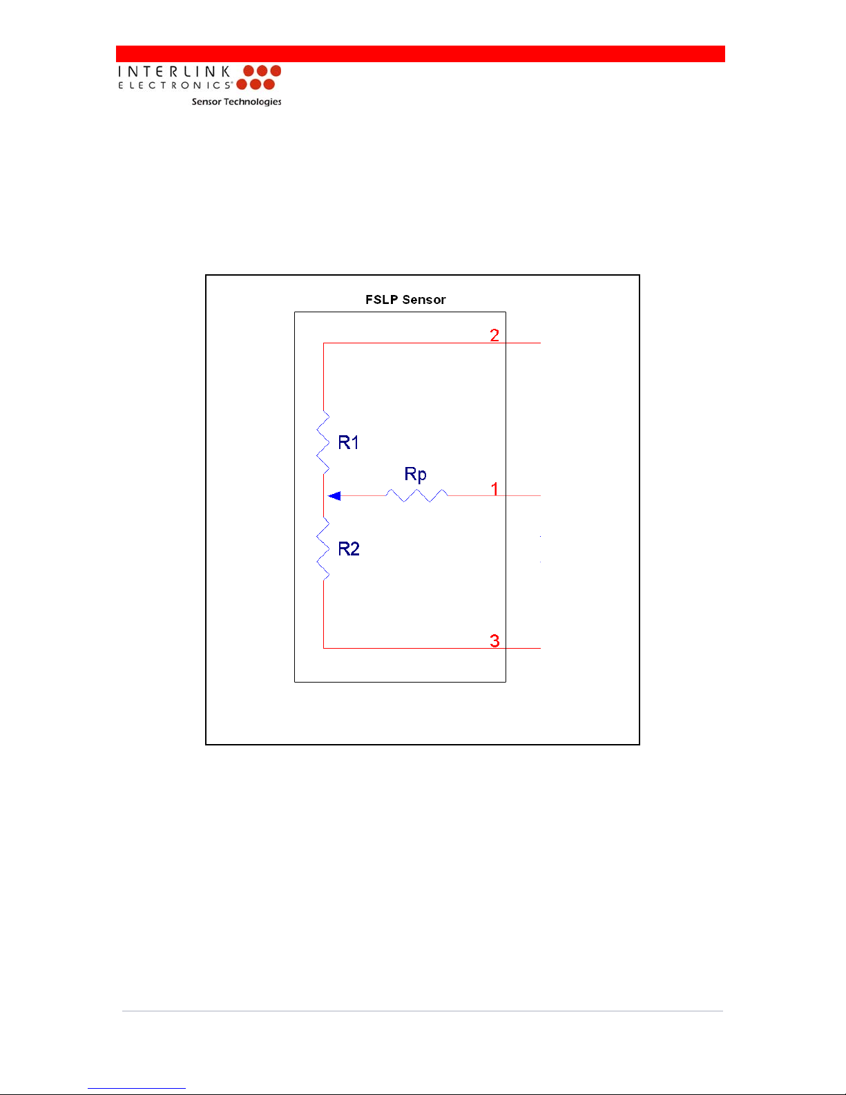
Figure 3 shows a schematic view of the sensor. Notice that the sensor is a three-terminal device
and when touched, has a circuit that is equivalent to three resistors. R1 is the resistance from
sensor terminal 2 to the touch spot. R2 is the resistance from the touch spot down to sensor
terminal 3. Rp is connected to the junction between R1 and R2 by the user’s touch. As the user
varies the touch spot from the top of the sensor to the bottom of the sensor, R1 becomes larger
and R2 becomes smaller. As the user presses harder, Rp decreases. Rp varies from around
300kΩat very light touches to 2kΩat extremely heavy touches. The resistance is roughly
proportional to the reciprocal of the force.
Figure 3: Schematic representation of the FSLP.

www.interlinkelectronics.com
5
Force Sensing Linear Potentiometer (FSLP)
Integration Guide
4.0 Mounting and Connection
4.1 Mounting
There are a few critical elements to consider when mounting the FSLP:
The mounting surface should be free of any raised features (e.g. copper traces on a PCB
or dust contamination) as they will interfere with the sensor’s proper operation.
If the sensor is being mounted to a PCB, it should be installed after PCB assembly is
complete. Heat generated during the soldering of components can damage the FSR.
When laminating the sensor, be sure to use a hard roller or other depression tool to
ensure proper bonding of the sensor’s pressure-sensitive adhesive and the removal of
any air bubbles.
4.2 FSLP Types
39.3±0.10
13.5±0.10
36.3
(ACTIVE AREA)
14.0
5.0
9.8
(ACTIVE AREA)
T=0.61±0.06
0.34±0.04
AA
Figure 4: Overall dimensions of the standard FSLP. All dimensions are in millimeters.

www.interlinkelectronics.com
6
Force Sensing Linear Potentiometer (FSLP)
Integration Guide
Figure 5: Overall dimensions of the 10 cm FSLP. All dimensions are in millimeters.
(shown without crimp terminals)
The 10cm FSLP can be customized to shorter pre-defined lengths. Refer to User’s
Customization Guide provided with the Hardware Development Kit.

www.interlinkelectronics.com
7
Force Sensing Linear Potentiometer (FSLP)
Integration Guide
4.3 Crimp Terminal Connections (10cm and derivatives only)
Figure 6: Crimp Terminal Connections.
www.interlinkelectronics.com
8
Force Sensing Linear Potentiometer (FSLP)
Integration Guide
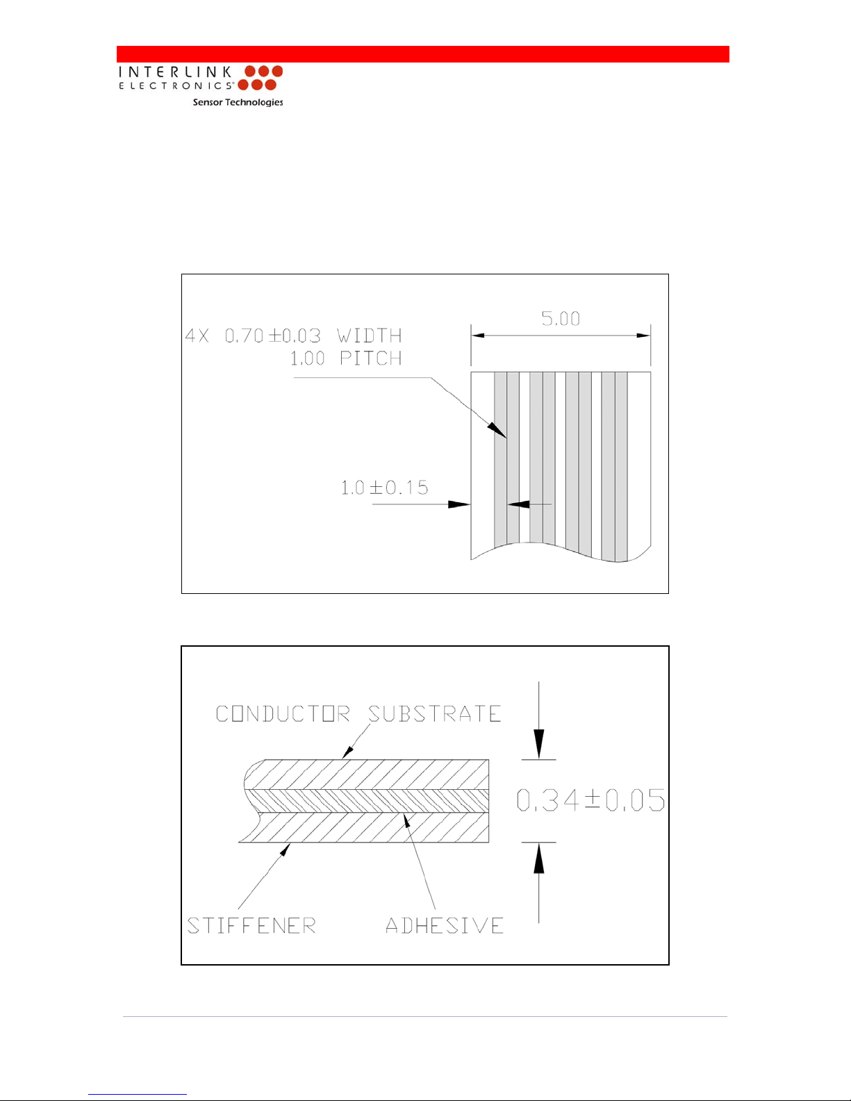
4.4 FFC Connection Method
Recommended Tail Connector:
JST 4-pin SMT connector (JST Part Number: 04FM-1.0SP-1.9-TF)
Interlink recommends the above connector, but any compatible connector may be used.
Refer to Figures 7 and 8 for sensor tail dimensions.
Figure 7: Top view of sensor tail. All dimensions are in millimeters.
Figure 8: Side view of sensor tail. All dimensions are in millimeters.
Table of contents


