manuals.online logo
Brands
  1. Home
  2. •
  3. Brands
  4. •
  5. Optex
  6. •
  7. Accessories
  8. •
  9. Optex OA-FLEX LITE User manual

Optex OA-FLEX LITE User manual

Other Optex Accessories manuals

Optex AX-250PLUS User manual

Optex

Optex AX-250PLUS User manual

Optex Fiber SenSys Terrain Defender TD 100 User manual

Optex

Optex Fiber SenSys Terrain Defender TD 100 User manual

Optex RXC-DT-X5 User manual

Optex

Optex RXC-DT-X5 User manual

Optex BGS-V2000 Series User manual

Optex

Optex BGS-V2000 Series User manual

Optex i-OneX T User manual

Optex

Optex i-OneX T User manual

Optex OA-203C User manual

Optex

Optex OA-203C User manual

Optex OA-4500S(E) User manual

Optex

Optex OA-4500S(E) User manual

Optex OAM-DUAL TE User manual

Optex

Optex OAM-DUAL TE User manual

Optex Reaction One User manual

Optex

Optex Reaction One User manual

Optex X-ZONE User manual

Optex

Optex X-ZONE User manual

Optex OA-PRESENCE T Installation manual

Optex

Optex OA-PRESENCE T Installation manual

Optex Elite OA-603 User manual

Optex

Optex Elite OA-603 User manual

Optex i-oneX T User manual

Optex

Optex i-oneX T User manual

Optex BS Series User manual

Optex

Optex BS Series User manual

Optex OVS-01GT User manual

Optex

Optex OVS-01GT User manual

Optex GEN-DC User manual

Optex

Optex GEN-DC User manual

Optex OA-FLEX T User manual

Optex

Optex OA-FLEX T User manual

Optex RC-20U User manual

Optex

Optex RC-20U User manual

Optex OA-FLEX AIR T User manual

Optex

Optex OA-FLEX AIR T User manual

Optex OA-FLEX T User manual

Optex

Optex OA-FLEX T User manual

Optex OVS-01GT User manual

Optex

Optex OVS-01GT User manual

Optex OA-AXIS T User manual

Optex

Optex OA-AXIS T User manual

Optex Pro Swing OA-Edge T User manual

Optex

Optex Pro Swing OA-Edge T User manual

Optex Pro Swing Elite ST User manual

Optex

Optex Pro Swing Elite ST User manual

Popular Accessories manuals by other brands

Quincy lab 140AE-1 operating manual

Quincy lab

Quincy lab 140AE-1 operating manual

HomePro ZIR000 user manual

HomePro

HomePro ZIR000 user manual

DOL 20SCR Technical user guide

DOL

DOL 20SCR Technical user guide

RAB Smart Task installation manual

RAB

RAB Smart Task installation manual

Kemppi KMS 300 quick guide

Kemppi

Kemppi KMS 300 quick guide

Stearns 57,500 Series Installation and service instructions

Stearns

Stearns 57,500 Series Installation and service instructions

iGuzzini TWILIGHT COPENAGHEN manual

iGuzzini

iGuzzini TWILIGHT COPENAGHEN manual

Adelaide Annexe & Canvas Avan Deluxe installation guide

Adelaide Annexe & Canvas

Adelaide Annexe & Canvas Avan Deluxe installation guide

OHAUS 5000 instruction manual

OHAUS

OHAUS 5000 instruction manual

HOME8 WLS1300 quick start guide

HOME8

HOME8 WLS1300 quick start guide

MAXBOTIX MaxSonar quick start guide

MAXBOTIX

MAXBOTIX MaxSonar quick start guide

ioSmart iSmart56 Installation and user guide

ioSmart

ioSmart iSmart56 Installation and user guide

Focusrite Scarlett 18i8 user guide

Focusrite

Focusrite Scarlett 18i8 user guide

Velleman ED38105 user manual

Velleman

Velleman ED38105 user manual

JumpSport SkyBounce user manual

JumpSport

JumpSport SkyBounce user manual

Prima-Temp PRIYA Instructions for use

Prima-Temp

Prima-Temp PRIYA Instructions for use

Tefcold BC85I-BC85I W user manual

Tefcold

Tefcold BC85I-BC85I W user manual

Vaisala WMS302 user guide

Vaisala

Vaisala WMS302 user guide

manuals.online logo
manuals.online logoBrands
  • About & Mission
  • Contact us
  • Privacy Policy
  • Terms and Conditions

Copyright 2025 Manuals.Online. All Rights Reserved.

OA-FLEX LITE
Quick Guide
5933620 SEP 2022
Manufacturer's statement
NOTE
WARNING
Pay special attention to sections with this symbol.
NOTE
WARNING
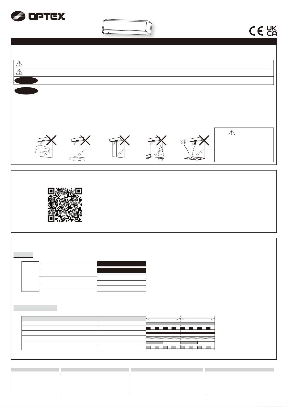
The following conditions are not suitable for sensor installation.
Wet Vibration ReflectionObjects
1000 ms 1000 ms
Signal saturation
Sensitivity too low
Slow Green blinking
Fast Green blinking
Status Operation indicator color
Stand-by Green
3rd - 5th row detection Orange
2nd row detection Red
1st row detection Red blinking
Sensor
Power
Power
COM.
N.O.
N.C.
Grey
Grey
White
Yellow
Green
1. This product is a non-contact switch intended for header mount or wall mount for use on an automatic sliding door. Do not use for any other applications.
2. When setting the sensor's detection area, make sure that there is no traffic around the installation site.
3. Before turning the power ON, check the wiring to prevent damage or malfunction of equipment connected to the product.
4. Only use the product as specified in the operation manual provided.
5. Be sure to install and adjust the sensor in accordance with the local laws and standards of the country in which the product is installed.
6. Before leaving the installation site make sure that the product is operating properly and instruct the building owner/operator on proper operation of the
door and the product.
7. The product settings can only be changed by an installer or service engineer.When changed, the changed settings and the date shall be registered in the
maintenance logbook accompanying the door.
Read this operation manual carefully before use to ensure proper operation of this product.
Failure to read this operation manual may cause improper operation and may result in serious injury or death of a person.
The meanings of the symbols are as follows.
Failure to follow the instructions that accompany this indication and improper handling may result in serious injury or death.
CAUTION Failure to follow the instructions that accompany this indication and improper handling may result in injury and/or damage to property.
Danger of electric shock
Do not wash, disassemble,rebuild
or repair the sensor,otherwise it
may cause electric shock or
breakdown of the equipment.
Link to Web manual
Link to web manual
Link zum Online-Handbuch
Link naar online handleiding
Lien vers le manuel en ligne
Collegamento al manuale online
Enlace al manual en línea
Wiring
Operation indicator
Fog,
Exhaust
Manufacturer
5-8-12 Ogoto Otsu 520-0101, Japan
www.optex.net
OPTEX CO., LTD.
Europe, Middle-East and Africa Subsidiary
OPTEX Technologies B.V.
Henricuskade 17, 2497 NB The Hague,
The Netherlands
Tel : +31(0)70 419 41 00
www.optex-europe.com
Legal representative (UK only)
OPTEX (EUROPE) LTD.
Unit 13 Cordwallis Park Clivemont Road
SL6 7BU Maidenhead, Berkshire United Kingdom
Tel : +44 (0)1628 631 000
www.optex-europe.com
North and South America Subsidiary
OPTEX INCORPORATED
10741 Walker Rd. Suite 300 Cypress,
CA 90630 U.S.A
Tel : +1(800)877 6656
www.optexamerica.com
EN
DE
NL
FR
IT
ES
Area depth angle adjustment
The angle of the detection area can be moved 7° either left or right in 2 steps.
Area width angle adjustment
Adjust the detection area width with the adjustment screws.
Snow mode
Immunity
8
OFF
8
ON
7
OFF
7
ON
Sensitivity
21
Low
21
S-High
21
Middle
21
High
Presence timer
2 s
43
30 s
43
180 s
43 43
Frequency
Setting 1
65
Setting 2
65
Setting 3
65
Setting 4
65
Front view [m(feet,inch)]
2.0
(6'7")
2.0
(6'7")
1.0
(3'3")
1.0
(3'3")
0
2.0(6'7")
3.0(9'10")
1 2 3 4 5 678
3.5°×23.5°×2
LeftRight
[m(feet,inch)]
Front view
Left Right
2.0
(6
'
7
"
)
1.0
(3
'
3
"
)
1.0
(3
'
3
"
)
0
2.0(6
'
7
"
)
3.0(9
'
10
"
)
2.0
(6
'
7
"
)
1.0
(3
'
3
"
)
1.0
(3
'
3
"
)
0
Set this switch to "ON" if the sensor is used in a region with snow or a lot of insects.
Set this switch to "ON" when the sensor operates by itself (Ghosting). When this switch is set to "ON", the actual
detection area may occur smaller.
12
OFF ON
12
5 rows
11
10
9
4 rows
11
10
9
3 rows
11
10
9
2 rows
11
10
9
1 row
11
10
9
Set the depth rows with dipswitches 9, 10, 11.
All other possible dipswitch settings will generate 5 rows active.
When this switch is set to "ON", presence detection is active in all rows.
When using more than one sensor close to each
other, set the frequency different for each sensor.
(1) Select the presence time.
(2) Turn the power OFF and ON again. Otherwise it may leave door open for the
duration of the presence time set.
(3) After making sure that the door closes, wait for 10 s before entering the
detection area to set the presence timer.
Set the sensitivity with dipswitches 1 and 2. Refer to below values for mounting
height and sensitivity. Make sure to finalize the proper setting dependent on site
condition.
Low or Middle : 2.0m to 2.5m / High : 2.3m to 2.7m / S-High : 2.5m to 3.0m
-6° +10°
DeepShallow
[m(feet,inch)]
ShallowDeep
2.0(6'7")
3.0(9'10")
Side view
2.0
(6
'
7
"
)
1.0
(3
'
3
"
)
0
3.0
(9
'
10
"
)
2.0
(6
'
7
"
)
1.0
(3
'
3
"
)
1.0
(3
'
3
"
)
0
0°
NOTE
1. Make sure that the detection area does not
overlap with the door/header, and there is no
highly reflecting object near the detection area
otherwise ghosting/signal saturation may occur.
2. When adjusting the depth angle < 0°, make
sure the sensor does not detect the door.
NOTE
When setting the detection area width, make
sure to turn the adjustment screws until it
clicks.
and cannot be eliminated 
independently.
1 2 7 8
Row adjustment
Presence detection
active in all rows
1 2
Left
eliminated
7 8
Right
eliminated
Function Comment
( Factory default settings)
Setting
Dipswitch settings
Area width adjustment
Area angle adjustment