Seeley Climate Wizard CW-H10 User manual

(English) (CW-H15)
INSTALLATION & OPERATION MANUAL
INDIRECT EVAPORATIVE COOLER
CW-H10, CW-H15, CW-H15S, CW-H15S Plus
2020 Models
Original English Instructions
ILL1916


SEELEY INTERNATIONAL
- INSTALLATION MANUAL 859749-A |3
TABLE OF CONTENTS
IMPORTANT SAFETY INSTRUCTIONS
Read & Save These Instructions For Future Reference 4
For Europe 4
For Australia, New Zealand & Other Non-European
Countries 4
For Australian Bushre Prone Areas 4
Warnings 4
Employer And Employee Responsibilities 4
Installer And Maintenance Contractors - Risk Assessment 5
Installer And Maintenance Contractors 5
Some Points To Consider 5
Other Important Requirements 5
Maintenance Note 5
COOLER VIEWS 6
COOLER EXPLODED VIEW 8
COOLER SPECIFICATIONS 9
Metric CW-H Models 9
Imperial CW-H Models 10
COOLER CONTENTS 11
COOLER INSTALLATION COMPONENTS 11
Optional Components 11
INSTALLATION 12
Cooler Location 12
Mounting/Support 12
Unpacking The Cooler 12
Moving The Cooler 12
Lifting The Cooler 12
Vibration Isolation 12
Drip-Tray 12
Supply Air Duct Connections 12
Exhaust Transition Assembly 13
Exhaust Duct Connection Requirements 13
Water Supply Installation 15
Water Supply Filtration 15
Water Hammer 15
Water Drain Installation 15
Electrical Supply Installation
(Australia, Europe - 3ph 380-415v) 16
SETUP 16
PLC Layout 16
CW-H Control Schemes 17
Option 1 Local Zone Control With Wall Control 17
Wall Controller / RS-485 Modbus Wiring 17
Wall Controller / RS-485 Modbus Node Address 18
Option 2 Building Management System Low Voltage 18
BMS Interface Terminals Layout And Function 18
Error Status Output Terminal 19
Cooler Operating Mode Input Terminals 19
Fan Speed Input Terminals 19
Cabling Requirements 19
BMS Terminal Connections 19
Example BMS Schematic 19
Option 3 PLC Manual Control 19
COMMISSIONING
Water Management System 20
Tank (Reservoir) Drain Valve Control 20
Inlet Solenoid Valve Control - Water 20
Pre-Wet Cycle 20
Pump Control 20
Chlorinator Control 20
Indirect Watering Cycle 20
Setting The Air Discharge Damper 21
Air Flow Balancing 21
INSTALLATION CHECKLIST
Installation 22
Commissioning 22
MAINTENANCE INSTRUCTIONS 23
Quarterly Inspection Procedures 23
Pump Maintenance & Replacement 24
Changing Pumps 24
Cleaning Pump Strainers & Impellors 24
Solenoid Valve Maintenance & Replacement 24
Chlorinator Maintenance & Replacement 25
Water Management Probe Maintenance & Replacement 25
Cleaning The Water Reservoir (Tank) 25
Drain Valve Maintenance & Replacement 26
Cleaning Or Replacing Inlet Air Filters 26
Changing Cooler Cores 27
Changing Cooler Cores - Orientation 27
Changing Cooler Chillcel Pads 28
Operating And Fault Code Diagnosis 29
MAINTENANCE SCHEDULE 32
PRODUCT WARRANTY 35
Warranty Terms And Information (Australia Only) 36
NOTES 38

4 |CW-H10, H15, H15S, H15S Plus 859749-A
IMPORTANT SAFETY INSTRUCTIONS
READ AND SAVE THESE INSTRUCTIONS
FOR FUTURE REFERENCE.
FOR EUROPE
This appliance can be used by children aged
from 8 years and above and persons with
reduced physical, sensory or mental capabilities
or lack of experience and knowledge if they
have been given supervision or instruction
concerning use of the appliance in a safe way
and understand the hazards involved. Children
shall not play with the appliance. Cleaning and
user maintenance shall not be made by children
without supervision.
FOR AUSTRALIA, NEW ZEALAND & OTHER
NON-EUROPEAN COUNTRIES
This appliance is not intended for use by
persons (including children) with reduced
physical, sensory or mental capabilities, or
lack of experience and knowledge, unless they
have been given supervision or instruction
concerning use of the appliance by a person
responsible for their safety. Children should be
supervised to ensure that they do not play with
the appliance.
Means for all pole disconnection must be
incorporated in the xed wiring in accordance
with the wiring rules, adjacent to or on the
cooler cabinet. If mounting on the cooler
cabinet, take care not to puncture the water
reservoir.
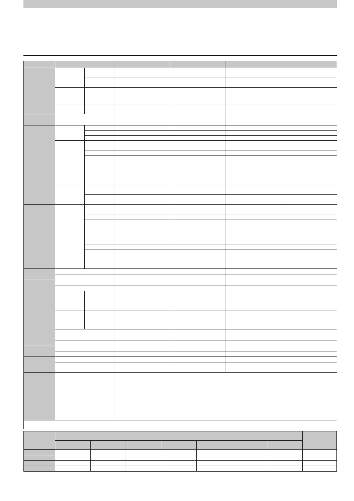
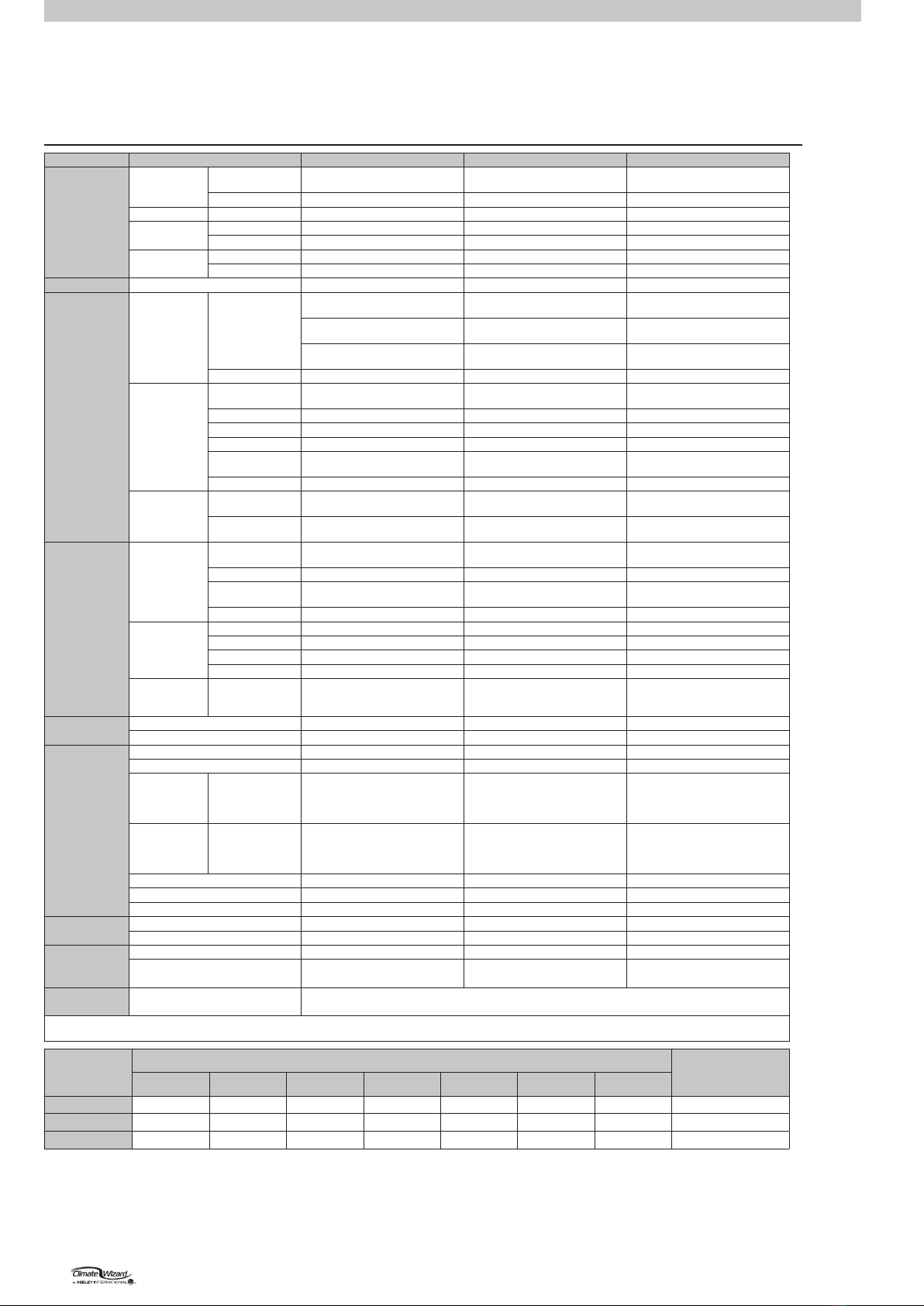
The following specications for the cooler water
supply are required:
Water Connection ½” BSP (Aus/Eur), ½” NPT
(USA)
Min Water Pressure 100kPa (15psi)
Max Water Pressure 800kPa (115psi)
Max Water Flow 20 L/min (5.3 gallons/min)
Max Water Temperature 40°C (104°F)
New hose sets supplied with the appliance are
to be used and old hose-sets should not be re-
used.
If the supply cord is damaged, it must be
replaced by the manufacturer, its service agent
or similarly qualied persons in order to avoid a
hazard.
CAUTION: In order to avoid a hazard due to
inadvertent resetting of the thermal cut-out,
this appliance must not be supplied through an
external switching device, such as a timer, or
connected to a circuit that is regularly switched
on and o by the utility.
FOR AUSTRALIAN BUSHFIRE PRONE
AREAS
WARNING If this evaporative cooler is installed
in a BAL-12.5 to 29 area the evaporative cooler
dropper duct and ashings shall be adequately
sealed at the roof to prevent gaps greater than
3mm. The dropper duct and ashings shall be
non-combustible.
WARNING: This cooler is NOT APPROVED
for installation in any bushre zoned area/
property (BAL-12.5 to BAL-FZ).
WARNING - TO REDUCE THE RISK OF
FIRE, ELECTRIC SHOCK, OR INJURY TO
PERSONS, OBSERVE THE FOLLOWING:
a) Use this unit only in the manner intended
by the manufacturer. If you have ques-
tions, contact the manufacturer.
b) Before servicing or cleaning unit, switch
power o at service panel and lock the
service disconnecting means to prevent
power from being switched on accidentally.
When the service disconnecting means
cannot be locked, securely fasten a prom-
inent warning device, such as a tag, to the
service panel.
c) Installation work and electrical wiring must
be done by qualied person(s) in accor-
dance with all applicable codes and stan-
dards, including re-rated construction.
d) When cutting or drilling into wall or ceiling,
do not damage electrical wiring and other
hidden utilities.
e) Do not use this fan with any Solid-State
Speed Control device.
f) Ducted fans must always be vented to the
outdoors.
EMPLOYER AND EMPLOYEE
RESPONSIBILITIES
The installation and maintenance of evaporative
coolers at height has the potential to create Oc-
cupational Health and Safety issues for those
involved. Installers are advised to ensure they
are familiar with the relevant State and Federal
legislation, such as Acts, Regulations, approved
Codes of Practice and Australian Standards,
which oer practical guidance on these health
and safety issues. Compliance with these reg-
ulations will require appropriate work practices,
equipment, training and qualications of work-
ers.
Seeley International provides the following in-
formation as a guide to contractors and employ-
ees to assist in minimising risk whilst working at
height.

SEELEY INTERNATIONAL
- INSTALLATION MANUAL 859749-A |5
IMPORTANT
As with any product that has moving parts
or is subject to wear and tear, it is VERY
IMPORTANT that you maintain your cooler
and have it regularly serviced. It is a condition
of warranty cover for your cooler that you
comply with all of the maintenance and
service requirements set out in this Manual.
Compliance with these requirements will
prolong the life of your cooler. Further, it is also
a condition of warranty cover that each item
in the Maintenance Schedule in the Manual is
lled out (by signing and dating it in the places
indicated) when the item is completed.
Any failure to carry out the required
maintenance and servicing, and any failure to
ll out the maintenance schedule, will void your
warranty.
MAINTENANCE NOTE
IMPORTANT SAFETY INSTRUCTIONS
INSTALLER AND MAINTENANCE
CONTRACTORS - RISK ASSESSMENT
Installer and Maintenance Contractors
A risk assessment of all hazardous tasks is
required under legislation. A risk assessment is
an essential element that should be conducted
before the commencement of work, to identify
and eliminate the risk of falls or to minimise
these risks by implementing control measures.
There is no need for this to be a complicated
process, it just is a matter of looking at the job
to be done and considering what action(s) are
necessary so the person doing the job does not
injure themselves.
This should be considered in terms of:
• What are the chances of an incident
happening?
• What could the possible consequence
be?
• What can you do to reduce, or better still,
completely get rid of the risk?
SOME POINTS TO CONSIDER
• What is the best and safest access to the
roof and working areas?
• If a worker is alone, who knows they are
there and if they get into diculty, how
can they summon help?
• (Call someone on the ground? Mobile
phone? etc.)
• What condition is the roof in? Should
the trusses, underside or surface be
checked?
• Does the worker have appropriate foot
wear? (Flat sole jogger type is advisable)
• Are all power cables / extension leads
safe and appropriately rated?
• Are all ladders, tools and equipment suit-
able in good condition?
• Where ladders are to be used, is there a
rm, stable base for them to stand on?
Can they be tied or secured in some way
at the top? Is the top of the ladder clear
of electricity supply cables?
• Is there a roof anchor to attach a har-
ness and lanyard to? If so, instruction
should be issued for the use of an ap-
proved harness or only suitably trained
people used.
• Are all tools and materials being used,
prevented from slipping and falling onto
a person at ground level? Is the area
below the work area suitably protected to
prevent persons walking in this area?
• Does the work schedule take into ac-
count weather conditions, allowing for
work to be suspended in high winds,
thunder storms/lightning or other types of
weather giving wet, slippery surfaces?
• Is there an on-going safety check system
of harnesses, ropes, ladders and access/
lifting equipment and where they exist
on roofs, anchor points before the com-
mencement of work?
• Is there a system which prevents em-
ployees from working on roofs if they are
unwell or under the inuence of drugs or
alcohol?
• Are there any special conditions to
consider i.e. excessive roof pitch, limited
ground area, fragile roof, electrical power
lines?
OTHER IMPORTANT REQUIREMENTS
• Never force parts to t because all parts
are designed to t together easily without
undue force.
• Never drill holes in the tank of the cooler.
• Check the proposed cooler location, to
ensure that it is structurally capable of
supporting the weight of the cooler, or
provide an adequate alternate load bear-
ing structure.
• Ensure the installation complies with all
local and national regulations with re-
gards to electrical, plumbing and bushre
construction requirements.

6 |CW-H10, H15, H15S, H15S Plus 859749-A
COOLER VIEWS
Dimensions are in mm (inches in brackets).
ISOMETRIC
CW-H10 views shown
TOP
REAR SIDE
BOTTOM
ILL3156-A
ILL3157-A
ILL3158-A
ILL3159-A
ILL3161-A
FRONT
ILL3160-A

SEELEY INTERNATIONAL
- INSTALLATION MANUAL 859749-A |7
COOLER VIEWS
ILL1916
2290
[90.2]
1969
[77.5]
1825
[71.9]
1500
[59.1]
ILL1918
ISOMETRIC
CW-H15 views shown
TOP
REAR SIDE
BOTTOM
ILL1916-C
ILL1918-C
ILL1917-C ILL1919-C
ILL1920-C
660
[26.0]
192
[7.6]
107
[4.2]
40
[1.6]
250
[9.8]
908
[35.7]
323
[12.7]
ILL1917
REAR COWLING PANEL AND TWO RIGHT FILTERS
HIDDEN FOR CLARITY
WATER INLET
DRAIN
482
[19.0]
150
[5.9]
SUPPLY DUCT
500x500
(19.7x19.7)
668
[26.3]
419
[16.5]
509
[20.0]
1300
[51.2]
481
[18.9]
650 [25.6]
ILL1919
MOUNTING BASE
EXHAUST DUCT
1822 [71.7] EXHAUST DUCT
217 [8.6]
1283
[50.5]
EXHAUST C/L
1171
[46.1]
MOUNTING BASE
1800 [70.9]
ILL2422
FRONT
ILL2422-C
50
[2.0]
400
[15.7]
800
[31.5]
1200
[47.2]
50
[2.0]
550
[21.7]
1150
[45.3]
1700
[66.9]
MOUNTING HOLES
10
[0.394]
TYP 16 PL
ILL1920
BASE FRAME UNDERSIDE
Dimensions are in mm (inches in brackets).

8 |CW-H10, H15, H15S, H15S Plus 859749-A
COOLER EXPLODED VIEW
ILL2423-B
1245
6
34
11
12
13
9
10
14
15
16
7
8
1 ASSEMBLYCOWLING
2 ELECTRONICS BOX
9TANK ASSEMBLY
INDEX DESCRIPTION
3 AIR FILTER ASSEMBLY
FRONT PANELS4
12 OUTLET TRANSITION ASSEMBLY
15 EXHAUST ASSEMBLYGRILLE
7 PUMP, DRAIN VALVE AND WATER PROBE
0 ASSEMBLY1 BASE FRAME
8 PUMPS, INLET SOLENOID AND CHLORINATOR
11 OUTER PANELS (RHS)
5 MOTOR AND FAN ASSEMBLY
13 DAMPER ASSEMBLY
6 INLET TRANSITION ASSEMBLY
14 ASSEMBLYCORE AND SPREADER
16 EXHAUST ASSEMBLYLID
ILL2423-B

SEELEY INTERNATIONAL
- INSTALLATION MANUAL 859749-A |9
COOLER SPECIFICATIONS
TECHNICAL SPECIFICATIONS - METRIC CW-H MODELS
FREQUENCY
(Hz)
Radiated Sound Power Level (dB(A) re 1pw) Octave Band Centre Frequency Total Sound
Power
dB(A) re 1pw
125 250 500 1k 2k 4k 8k
CW-H10
70 60 58 57 54 50 42 63
CW-H15
84 68 65 62 55 51 44 70
CW-H15S
68 69 64 63 60 53 44 73
CW-H15S Plus 71 70 66 64 61 55 48 75
MODEL: CW-H10 CW-H15 CW-H15S CW-H15S Plus
OPTIMUM
PERFORMANCE
Airow Supply Air 800 L/s @ 180 Pa 1100 L/s @ 150 Pa
3960 m3/h @ 150 Pa
1100 L/s @ 120 Pa
3960 m3/h @ 120 Pa
1600 L/s @ 80 Pa
5760 m3/h @ 80 Pa
Exhaust Air 655 L/s 900 L/s
3240 m3/h
900 L/s
3240 m3/h
530 L/s
1910 m3/h
Temperature* Supply Air 19.5 oC 19.5 oC 15.8 oC 17.4 oC
Cooling
Capacity*
Standalone 8 kW 11 kW 16 kW 20 kW
Pre-Cooling 18 kW 25 kW 29 kW 40 kW
COP* Standalone 5 6 8.5 9.5
Pre-Cooling 12 14 16 19
ENVIRONMENT Maximum Inlet Air
Temperature
55 oC 55 oC 55 oC 55 oC
SERVICES Electrical Voltage 380-415 V / 3N~ / 50Hz 380-415 V / 3N~ / 50Hz 380-415 V / 3N~ / 50Hz 380-415 V / 3N~ / 50Hz
Current 4.9 A 4.9 A 4.9 A 4.9 A
Input Power 1.50 kW 1.80 kW 1.80 kW 2.10 kW
Water Supply 20 L/min @
100 kPa - 800 kPa
20 L/min @
100 kPa - 800 kPa
20 L/min @
100 kPa - 800 kPa
20 L/min @
100 kPa - 800 kPa
Max Temp. 40 oC 40 oC 40 oC 40 oC
Inlet 1/2" Male BSP 1/2" Male BSP 1/2" Male BSP 1/2" Male BSP
Consumption* 44 L/hr 56 L/hr 60 L/hr 72 L/hr
Drain 40mm Male BSP or 20mm
Push-On
40mm Male BSP or 20mm
Push-On
40mm Male BSP or 20mm
Push-On
40mm Male BSP or 20mm
Push-On
Drain Flow
Rate
15 L/m 15 L/m 15 L/m 15 L/m
Duct
Connections
Supply Air Side Discharge
500 x 500 mm
Side Discharge
500 x 500 mm
Side Discharge
500 x 500 mm
Side Discharge
500 x 500 mm
Exhaust Air Side Discharge
1230 x 260 mm
Side Discharge
1825 x 220 mm
Side Discharge
1825 x 220 mm
Side Discharge
1825 x 220 mm
AIR
SYSTEMS
Supply Air
Fan/Motor
Fan 1x 560mm Centrifugal
Backward Curve
1x 560mm Centrifugal
Backward Curve
1x 560mm Centrifugal
Backward Curve
1x 560mm Centrifugal
Backward Curve
Motor 3.5 kW 3.5 kW 3.5 kW 3.5 kW
Control Variable Speed, ECM, PWM
Control
Variable Speed, ECM, PWM
Control
Variable Speed, ECM, PWM
Control
Variable Speed, ECM, PWM
Control
Max Speed 1285 rpm 1390 rpm 1390 rpm 1450 rpm
Exhaust Air
Fan/Motor
Fan NONE NONE NONE NONE
Motor
Control
Max Speed
Air Filters Inlet G4 Pleated Washable
305 x 610 x 50mm - 2
610 x 610 x 50mm - 1
6x G4 Pleated Washable
457 x 508 x 50mm
6x G4 Pleated Washable
457 x 508 x 50mm
6x G4 Pleated Washable
457 x 508 x 50mm
HEAT
EXCHANGERS
Indirect Evaporative 2 Cores 3 Cores 3 Cores 3 Cores
Direct Evaporative NONE NONE 3 Chillcel Pads 3 Chillcel Pads
WATER
SYSTEMS
Tank (Reservoir) Capacity 45 L 65 L 65 L 65 L
Inlet Valve 12 Vdc Solenoid Valve 12 Vdc Solenoid Valve 12 Vdc Solenoid Valve 12 Vdc Solenoid Valve
Pumps Indirect Heat
Exchangers
2 Pumps
13 LPM @ 1.5m Head
230V 50Hz
Input Power 30W ea.
2 Pumps
13 LPM @ 1.5m Head
230V 50Hz
Input Power 30W ea.
2 Pumps
13 LPM @ 1.5m Head
230V 50Hz
Input Power 30W ea.
2 Pumps
13 LPM @ 1.5m Head
230V 50Hz
Input Power 30W ea.
Pump Direct Heat
Exchangers
NONE NONE 1 Pump
13 LPM @ 1.5m Head
230V 50Hz
Input Power 30W ea.
1 Pump
13 LPM @ 1.5m Head
230V 50Hz
Input Power 30W ea.
Salinity Management Conductivity Probe Conductivity Probe Conductivity Probe Conductivity Probe
Chlorinator 12 Vdc 12 Vdc 12 Vdc 12 Vdc
Drain Valve 12 Vdc Vertical 12 Vdc Vertical 12 Vdc Vertical 12 Vdc Vertical
DIMENSIONS Shipping 2050L x 1375W x 1280mm H 2290L x 1950W x 1270mm H 2290L x 1950W x 1270mm H 2290L x 1950W x 1270mm H
Operating inc. Accessories 2330L x 1230W x 1325mm H 2290L x 1825W x 1285mm H 2290L x 1825W x 1285mm H 2290L x 1825W x 1285mm H
WEIGHT Shipping 250 kg 340 kg 355 kg 355 kg
Operating inc. Water/
Accessories
255 kg 330 kg 345 kg 345 kg
STANDARDS
COMPLIANCE
Electrical Safety
IEC 60335.1:2011 +A1 +A2
IEC 60335.2.98:2002 +A1 +A2
Ingress Protection
IEC 60529:2011
EMC
IEC 61000-6-3:2006
IEC 61000-6-1:2005
EMF
EN 62233:2008
* Supply Air Temperatures, Cooling Capacities, COP and Water Consumption tested to Australian Standard AS 2913-2000 and ASHRAE 143 with design condition of: 38 C dry-bulb, 21 C wet-bulb
and 27.4 C room exit temperature.

10 |CW-H10, H15, H15S, H15S Plus 859749-A
COOLER SPECIFICATIONS
TECHNICAL SPECIFICATIONS - IMPERIAL CW-H MODELS
FREQUENCY
(Hz)
Radiated Sound Power Level (dB(A) re 1pw) Octave Band Centre Frequency Total Sound Power
dB(A) re 1pw
125 250 500 1k 2k 4k 8k
CW-H15
84 68 65 62 55 51 44 70
CW-H15S
68 69 64 63 60 53 44 73
CW-H15S Plus 71 70 66 64 61 55 48 75
MODEL: CW-H15 CW-H15S CW-H15S Plus
OPTIMUM
PERFORMANCE
Airow Supply Air 2330 CFM @
0.60 in.w.g.
2330 CFM @
0.52 in.w.g.
3390 CFM @
0.32 in.w.g.
Exhaust Air 1910 CFM 1910 CFM 1270 CFM
Temperature* Supply Air 67.1 oF 60.4 oF 63.3 oF
Cooling
Capacity*
Standalone 37,000 BTU/hr 48,500 BTU/hr 65,500 BTU/hr
Pre-Cooling 82,000 BTU/hr 93,800 BTU/hr 135,500 BTU/hr
EER* Standalone 21 28 30
Pre-Cooling 46 53 61
ENVIRONMENT Maximum Inlet Air Temperature 131 oF 131 oF 131 oF
SERVICES Electrical Voltage
Maximum Rated
Current
440-480 V / 3~ / 60Hz
3A FLA / 8.5 MCA / 15 MOPD
440-480 V / 3~ / 60Hz
3A FLA / 8.5 MCA / 15 MOPD
440-480 V / 3~ / 60Hz
3A FLA / 8.5 MCA / 15 MOPD
200-240 V / 3~ / 60Hz
6A FLA / 14.5 MCA / 20 MOPD
200-240 V / 3~ / 60Hz
6A FLA / 14.5 MCA / 20 MOPD
200-240 V / 3~ / 60Hz
6A FLA / 14.5 MCA / 20 MOPD
200-240 V / 1~ / 60Hz
8A FLA / 11.5 MCA / 15 MOPD
200-240 V / 1~ / 60Hz
8A FLA / 12 MCA / 15 MOPD
200-240 V / 1~ / 60Hz
8A FLA / 12 MCA / 15 MOPD
Input Power 1.8 kW 1.8 kW 2.2 kW
Water Supply 5.3 GPM @
15 PSI - 115 PSI
5.3 GPM @
15 PSI - 115 PSI
5.3 GPM @
15 PSI - 115 PSI
Max Temp. 105 oF 105 oF 105 oF
Inlet 1/2" Male NPT 1/2" Male NPT 1/2" Male NPT
Consumption* 15 GPH 16 GPH 19 GPH
Drain 40mm Male BSP or
20mm Push-On
40mm Male BSP or
20mm Push-On
40mm Male BSP or
20mm Push-On
Drain Flow Rate 4 GPM 4 GPM 4 GPM
Duct
Connections
Supply Air Side Discharge
20 x 20 in
Side Discharge
20 x 20 in
Side Discharge
20 x 20 in
Exhaust Air Side Discharge
72 x 9 in
Side Discharge
72 x 9 in
Side Discharge
72 x 9 in
AIR
SYSTEMS
Supply Air
Fan/Motor
Fan 1x 22" Centrifugal
Backward Curve
1x 22" Centrifugal
Backward Curve
1x 22" Centrifugal
Backward Curve
Motor 3.5 kW 3.5 kW 3.5 kW
Control Variable Speed, ECM, PWM
Control
Variable Speed, ECM, PWM
Control
Variable Speed, ECM, PWM
Control
Max Speed 1350 rpm 1350 rpm 1460 rpm
Exhaust Air
Fan/Motor
Fan NONE NONE NONE
Motor
Control
Max Speed
Air Filters Inlet MERV 10 Disposable
12" x 24" x 2" - 3
24" x 24" x 2" - 1
MERV 10 Disposable
12" x 24" x 2" - 3
24" x 24" x 2" - 1
MERV 10 Disposable
12" x 24" x 2" - 3
24" x 24" x 2" - 1
HEAT
EXCHANGERS
Indirect Evaporative 3 Cores 3 Cores 3 Cores
Direct Evaporative NONE 3 Chillcel Pads 3 Chillcel Pads
WATER
SYSTEMS
Tank (Reservoir) Capacity 17.2 Gal 17.2 Gal 17.2 Gal
Inlet Valve 12 Vdc Solenoid Valve 12 Vdc Solenoid Valve 12 Vdc Solenoid Valve
Pumps Indirect Heat
Exchangers
3 Pumps
3.4 GPM @ 60" Head
220-240V 60Hz
Input Power 32W ea.
3 Pumps
3.4 GPM @ 60" Head
220-240V 60Hz
Input Power 32W ea.
3 Pumps
3.4 GPM @ 60" Head
220-240V 60Hz
Input Power 32W ea.
Pump Direct Heat
Exchangers
NONE 1 Pump
3.4 GPM @ 60" Head
220-240V 60Hz
Input Power 32W ea.
1 Pump
3.4 GPM @ 60" Head
220-240V 60Hz
Input Power 32W ea.
Salinity Management Conductivity Probe Conductivity Probe Conductivity Probe
Chlorinator 12 Vdc 12 Vdc 12 Vdc
Drain Valve 12 Vdc Vertical 12 Vdc Vertical 12 Vdc Vertical
DIMENSIONS Shipping 81" L x 79" W x 51" H 81" L x 79" W x 51" H 81" L x 79" W x 51" H
Operating inc. Accessories 92" L x 72" W x 51" H 92" L x 72" W x 51" H 92" L x 72" W x 51" H
WEIGHT Shipping 750 lb 783 lb 783 lb
Operating inc. Water/
Accessories
728 lb 761 lb 761 lb
STANDARDS
COMPLIANCE
ETL Listed to UL 507
OSHPD Special Sesimic Certification Preapproval (OSP) (California)
* Supply Air Temperatures, Cooling Capacities, COP and Water Consumption tested to ASHRAE 143 with design condition of: 100 F dry-bulb, 70 F wet-bulb and 81 F room exit
temperature.

SEELEY INTERNATIONAL
- INSTALLATION MANUAL 859749-A |11
COOLER CONTENTS
COOLER INSTALLATION COMPONENTS
OPTIONAL COMPONENTS
Item Part
No. Description QTY
1859749 Cooler Instruction - Installation, Operation,
Maintenance 1
2879345 Warranty Card (USA Only) 1
3A
3B
3C
861883
593104
861593
Adaptor Drain Elbow
Adaptor, Drain 32/20mm
Nut, Pipe Fitting 1.5” BSP
1
1
1
4- Handle, Control Box 1
5A
5B
637994
637393
Exhaust Centre Post CW-H15, H15S, H15S
Plus
Exhaust Centre Post CW-H10
1
6A
6B
6C
6D
6E
6F
805597
804446
804422
864341
864385
864372
Screw 8AB x ½” Pan Phill SS
Screw SEMS HX 14*3/4" ZNP
Plastic Grommet Size 14
Screw Set SHCS M6*35mm SS
Washer Flat M6*12.5OD*1.2 SS
Washer Flat NYLON M8*16OD
10
11
5
4
4
4
7931685 Exhaust Side Rails (1176mm Long)
(UNDER LID)
2
8A
8B
834789
834790
Exhaust Grille (869x205)
CW-H15, H15S, H15S Plus
(UNDER LID)
Exhaust Grille (571x247) CW-H10
(UNDER LID)
1
9637999
Exhaust Cap
CW-H15S Plus Only
(UNDER LID)
2
10 862801 Conversion Instruction for Supercool units 1
Item Seeley
Part Description
1121956 Wall Control Kit
2A
2B
134192
134215
Roofstand 0-10O(CW-H10)
Roofstand 0-10O (CW-H15, H15S, H15S Plus)
ITEM 7
ITEM 8A/8B
ITEM 9
ITEM 10
ITEM 1 ITEM 2 ITEM 3A
ITEM 4
ITEM 3C
ITEM 3B
WARRANTY INFORMATION
DUCTED INDIRECT EVAPORATIVE
AIR COOLER
INTERNATIONAL
ILL2424-C
ITEM 5A 5BS&
ITEM 66 6SA,B&D
ITEM 66SE&F
ITEM 1 ITEM 2
ILL2425-A
ILL2425-B
ILL2424-B

12 |CW-H10, H15, H15S, H15S Plus 859749-A
INSTALLATION
COOLER LOCATION
Check the proposed cooler location, to ensure that it is
structurally capable of supporting the weight of the cooler, or
provide an adequate alternate load bearing structure.
Model Shipping Weight Operating Weight
CW-H10 250kg (550 lb) 255kg (560 lb)
CW-H15 340kg (750 lb) 330kg (728 lb)
CW-H15S, H15S Plus 355kg (783 lb) 345kg (761 lb)
Always locate the cooler where it will receive a plentiful supply
of fresh air, NOT in a recess where it may be starved for air or
where the air is polluted.
Air exiting the exhaust hood is warm and heavily laden with
moisture. Ensure the cooler’s exhaust outlet location will not
cause corrosion or damage to other nearby items. Do not allow
exhaust air to re-circulate into the air intake of the cooler.
Ensure the location is a minimum of:
• 3.0m (10’) from a solid fuel heater ue,
• 1.5m (5’) from a gas ue,
• 5.0m (16’) from a sewer vent
• Rear = Min 1.0m (3.5’) from a wall, 1.0m (3.5’) at sides to
allow easy access for maintenance and core replacement.
ILL1925-A
Allow adequate access to and around the cooler for
maintenance. Provision must be made for access to electricity,
water supplies and drains.
Note! Do you need to discuss the installation of items like
safety anchor points with the customer?
MOUNTING/SUPPORT
Industry standard support frames can be used with this cooler.
Recommended steel specication:
50 x 50 x 3mm (2” x 2” x 1/8”) RHS Galvanized or Painted
Specic CW-H Roofstands are available for order via Seeley
International to suit cooler size and accommodating 5 or 10
degree roof pitches.
CW-H10: 0-10º - P/No. 134192
CW-H15: 0-10º - P/No. 134215
ILL2426-A
ILL2426-A
CW-H10:
A = 1300mm (51.2”) x 1206mm (47.5”)
CW-H15, H15S, H15S Plus:
A = 1300mm (51.2”) x 1800mm (70.9”)
CW-H10, CW-H15, H15S, H15S Plus:
B = 50mm min (2” min.)
Angle to match roof pitch
UNPACKING THE COOLER
The cooler will be delivered wrapped in a plastic stretch wrap
lm which will need to be removed before installation. A small
bag of installation components along with the exhaust transition
side rails and grilles can be found under the lid of the main
cabinet of the cooler. The exhaust transition will need to be
raised into place before operation.
WARNING: Once unwrapped, the exhaust transition assembly
should be tted together as soon as practicable to avoid loose
components becoming lost/damaged and/or a hazard.
MOVING THE COOLER
The cooler has in-built fork-truck tyne openings in the base for
ease of movement. The openings can also be used with lifting
straps or slings (refer diagram & see below).
ILL1916-C
ILL1916-A
Min. Fork tyne gap
= 460mm (18.2”)
LIFTING THE COOLER
The cooler may be lifted either by fork-truck or crane with slings.
The method for lifting by crane is by lifting straps through the
cooler base fork-truck tyne openings. Do not attempt to lift using
any cabinet features or by retro-tting lifting lugs. The cabinet
may be damaged and/or lift safety compromised.
It is recommended to use a spreader bar on the straps or slings
and/or to protect the upper edges of the cooler with a corner
protector beneath the lifting straps to avoid any damage to the
cabinet during the lift.
VIBRATION ISOLATION
Wae pads are recommended to be used under each corner
of the cooler. Pad size approx. 200mm (8”) x 200mm (8”). Use
industry standard methods of xing to the building structure.
DRIP-TRAY
When Climate Wizard coolers are installed indoors, or
anywhere that water leakage could cause damage, install
a corrosion resistant drip tray under the whole machine.
Recommended sizes:
CW-H10:
1500w x 1300d x 50h mm (59”w x 51”d x 2”h)
CW-H15, H15S, H15S PLUS:
1500w x 1900d x 50h mm (59”w x 75”d x 2”h)
Apply silicone sealant between drip-tray and cooler base at
every xing.
SUPPLY AIR DUCT CONNECTIONS
Vibration absorbing exible connections are recommended
for all duct connections to the cooler, for any ducts that are
attached to the building structure. All ducts attached to the
exible connection must be independently supported.

SEELEY INTERNATIONAL
- INSTALLATION MANUAL 859749-A |13
INSTALLATION
8. Fit the supplied 4 x M6 x 35MM SET SCREW, STAINLESS
STEEL FLAT WASHER, NYLON FLAT WASHER to the tops
of both core access doors. Apply a liberal coat of anti-seize
paste to the screw thread prior to tment.
EXHAUST TRANSITION ASSEMBLY
The exhaust transition is supplied in knock-down form and its
components are to be found beneath the lid of the cooler and
inside the component kit.
1. Lift the large top panel and locate;
• 2 x EXHAUST SIDE RAILS (1176mm Long)
• 2 x EXHAUST GRILLE
• 2 x EXHAUST CAPS (CW-H15S Plus Only)
2. Fit the EXHAUST SIDE RAILS to the inside vertical faces
of the large top panel with the supplied 10 x SCREW PAN
PHILLIPS 8AB*1/2” SS. Ensure the foam seal faces down.
ILL2427-A
ILL2427-A
3. Fit the supplied 3 x PLASTIC GROMMET SIZE 14 to the
rear lid panel upstand square holes.
ILL2428-A
ILL2428-A
4. Fit the supplied 2 x PLASTIC GROMMET SIZE 14 to the
EXHAUST CENTRE POST.
ILL2429-A
ILL2429-A
5. Position the large top panel over the top of the cooler, with
the rear u-channel over the top of the upstand, the side rails
sitting on the tops of the cooler side walls and the end posts
sitting on the outside of the front tray.
ILL2430-A
ILL2428-A
6. Slip the 2 x EXHAUST GRILLE and 1 x EXHAUST CENTRE
POST into position, retained inside the top panel front
u-channel.
CW-H15S Plus ONLY: Before tting to the cooler, slide an
EXHAUST CAP over the back of each EXHAUST GRILLE.
The EXHAUST CAP covers the top portion of the EXHAUST
GRILLE, and is designed to optimise the CW-H15S Supercool
performance.
ILL2431-A
7. Screw the exhaust transition assembly to the cooler body
with the supplied 11 x SCREW SEMS HEX 14 x 3/4” ZP.
3 x Rear Upstand, 3 x Left Side, 3 x Right Side, 2 x Centre
Post.
ILL2432-A
ILL2432-A
EXHAUST DUCT CONNECTION REQUIREMENTS
If required, the exhaust discharge opening may be ducted away
from the cooler. When designing the exhaust duct please note
the following;
• The exhaust air is warm and heavily laden with moisture.
Ensure the exhaust opening is located and oriented in such a
way as to avoid exhaust air re-entering the cooler inlet.
• Access to the heat exchanger cores requires the removal of
the cooler lid/exhaust transition. Ensure any additional ducting
is readily removable and/or lightweight.
• Where an installation requires extended exhaust ducts, the
increase in static load should not exceed 20 Pa (0.08 in wg).

14 |CW-H10, H15, H15S, H15S Plus 859749-A
INSTALLATION
The CW-H15S and CW-H15S Plus coolers are tted with
Chillcel pads, providing additional Direct Evaporative Cooling
(DEC).
They can be congured in two ways;
ILL3663-A
ILL3665-A
ILL2431-A
STEP 1 - EXHAUST CAPS
MODEL PERFORMANCE
Supply Airow
Rate
External Static
Pressure
CW-H15S 1100 L/s 120 Pa
3960 m3/h
2330 CFM 0.52 in.w.g.
CW-H15S Plus 1600 L/s 80 Pa
5760 m3/h
3390 CFM 0.32 in.w.g.
To correctly congure this cooler, ensure the following steps are
followed during the installation and commissioning process;
MODEL FIT EXHAUST CAPS?
CW-H15S NO
CW-H15S Plus YES
This CW-H cooler has been supplied with 2x Exhaust Caps
(P/N 637999), shipped loose under other exhaust components.
For CW-H15S PLUS ONLY slide an EXHAUST CAP over the
back of each EXHAUST GRILLE. The EXHAUST CAP covers
the top portion of the EXHAUST GRILLE and is designed to
optimise the CW-H15S PLUS performance.
FIT EXHAUST CAPS TO BACK OF EXHAUST GRILLE
STEP 2 - SET CORRECT DEVICE TYPE
MODEL CHANGE DEVICE TYPE?
CW-H15S YES
CW-H15S Plus NO - FACTORY DEFAULT
SETTING IS CORRECT
For CW-H15S ONLY access the SETUP menu on the PLC to
change DEVICE TYPE.
ILL3664-A
Push and hold the RIGHT
button until the password
screen is displayed.
Use the navigation LEFT/
RIGHT and UP/DOWN buttons
to enter password “7378” and
push OK to display the SETUP
screen.
Use the navigation UP/DOWN
buttons to move the cursor to
DEVICE TYPE and push OK
Push OK to activate the eld.
Use the navigation UP/DOWN
buttons to select CW-H15S.
Push OK to save the setting.
Push and hold the LEFT
button to return to the previous
menu. Repeat until the display
returns to the “CONTROL”
menu.
All CW-H coolers require the the supply air plenum pressure to
be correctly set. Follow the detailed instructions set out in the
Commissioning Section of the enclosed Installation, Operating
and Maintenance manual.
STEP 3 - SET SUPPLY AIR PLENUM PRESSURE
MODEL PLENUM PRESSURE
CW-H15S 175 Pa (0.70 in.w.g.)
CW-H15S Plus 210 Pa (0.84 in.w.g.)
ILL3665-A
ILL3664-A
ILL3666-A
ILL3667-A
ILL3666-A
ILL3665-A
ILL3667-A
ILL3668-A
ILL3668-A

SEELEY INTERNATIONAL
- INSTALLATION MANUAL 859749-A |15
WATER SUPPLY INSTALLATION
Climate Wizard requires a permanent water supply to be
connected.
Installation of the water supply to the cooler must conform to
local plumbing rules, regulations and standards:
The following specications for water supply are required:
• Water Connections:
½” BSP (Aus/Eur), ½” NPT (USA)
male connection supplied suitable for a compression tting.
• Water Supply:
100kPa (15psi) - 800 kPa (115psi)
MAXIMUM @ 20L/min (5.3 gal/min)
• Water Supply Temperature:
40°C (105°F) MAXIMUM
• Water Supply Salinity:
100 to 1150µS/cm
Important! If the water pressure exceeds this maximum
specication then a pressure reducing valve is required and
must be supplied and tted by the installer.
The installer must provide a manual 1/4 turn ball type shut o
valve (do not use a stop cock) in the water supply line adjacent
to the cooler, subject to local plumbing regulations. This allows
the water supply to be isolated whenever work needs to be
done on the cooler.
In areas subject to freezing, the water line needs a drain
down facility.
WATER SUPPLY FILTRATION
Seeley International requires an inlet lter to be installed on
the water supply line, external to the Climate Wizard cooler
to prevent any debris from entering and damaging cooler
components.
Important! Flush the water pipe to remove any contaminants
(swarf, lings or dirt) before nal tting. Contaminants can lodge
in the solenoid, preventing it from functioning correctly.
Climate Wizard’s water management system is designed to
use water that is suitable to be classied as ‘potable’ and t for
human consumption. If alternative water (including rain water)
is to be used that contains high levels of salinity, hardness,
acidity or chemical contaminants, then additional ltration or
treatment systems should be employed to render the water
‘potable’.
WATER HAMMER
Not all installation pipeworks are the same, and some may
require additional prevention against water hammer.
If water hammer is a problem, it is the responsibility of the
Installer to t an appropriate water hammer arresting device
external to the cooler.
WATER DRAIN INSTALLATION
Climate Wizard coolers require a permanent water drain to
be connected. A built-in Drain Valve, controlled by the water
management system, releases water from the cooler when
required.
The cooler installation kit contains components to congure the
Drain Valve discharge to one of the following options;
ACCESS COVER
FOR DRAIN VALVE
CONNECTION
WATER CONNECTION
1/2”MALE NIPPLE
(Water connection may
require an adaptor to
suit local pipe sizes)
660mm
(”)26
200mm
(”)7.9
REAR VIEW
ILL1940-B
DO NOT OVER-
TIGHTEN
OR CROSS-
THREAD
COMPRESSION
FITTINGS
ONTO THE PLASTIC
WATER INLET
NIPPLE.
ILL1940-B
The correct drain system must be used. Water drained from
the drain valve is high in salinity and must be carried away
to a suitable discharge point on the building or property, in
accordance with local regulations. It is a requirement of
Seeley International - Never drain the water directly onto
the roof.
• Down Discharge 1.5” (40mm) BSP Male
• Down Discharge 20mm Push On Hose
• Rear Discharge 1.5” (40mm) BSP Male
• Rear Discharge 20mm Push On Hose
An access panel can be removed for rear discharge options.
ILL2442-C
ILL2442-A
ILL2443-A
ILL2442-A
INSTALLATION

16 |CW-H10, H15, H15S, H15S Plus 859749-A
INSTALLATION
SETUP
PLC LAYOUT
ILL3622-A
10
61
2
3
4
5
7
8
9
Item Description Item Description
1
UP – moves cursor up one
level or increase value in edit
mode
6Green LED – Power Status
2
DOWN – moves cursor down
one level or decrease value in
edit mode
7
Red LED – Fault Status.
Number of ashes indicates
fault code
3
RIGHT – moves cursor to the
next variable or opens next
page
8
Yellow LED – Chlorinator
Status. Number of ashes
indicates chlorinator condition
4
LEFT – moves cursor to
previous variable or opens
previous page
9
Green LED – Flashes if wall
control/MODBUS master is
connected
5OK (ENTER) – select/edit value 10 USB Type A for USB memory
stick
ILL3622-A
Use the navigation LEFT/RIGHT buttons to switch between the
“CONTROL” menu and the “MONITOR” menu.
15
6
7
8
2
4
3
ILL3623-A
ILL3623-A
Item Description Item Description
1
Displays status of the Water
Low Probe. Filled when Wet
and empty when Dry.
5
Displays water salinity level
(µS/cm) measured by 3 pin
probe.
2
Displays status of the Water
High Probe. Filled when Wet
and empty when Dry.
6
Displays the fan 0-10Vdc
analogue output from PLC to
fan.
3
Displays status of the Inlet
Water Solenoid valve. Filled
when ON and empty when
OFF.
7Displays the chlorinator output
signal in % PWM.
4
Displays status of the Drain
Valve. Filled when OPEN and
empty when CLOSE.
8
Displays status of chlorinator
polarity, lled for forward
polarity and empty for reverse
polarity.
ELECTRICAL SUPPLY INSTALLATION
(AUSTRALIA, EUROPE - 3PH 380-415V)
Please Note! There are specic models for regional specic
voltages and frequencies which are not interchangeable,
as these require diering component congurations that vary
according to the supply frequency and voltage. Specically, the
main fan motor, 3 phase lter, transformer and pump are unique
to the voltage/frequency of supply.
INSTALLATION OF THE COOLER MUST CONFORM
TO LOCAL ELECTRICAL RULES, REGULATIONS AND
STANDARDS.
It is a requirement of Seeley International that all coolers
be wired with a dedicated circuit and circuit breaker to the
distribution board, incorporating an isolation switch in the xed
wiring with all pole disconnection from the mains power in
accordance with the local wiring rules.
Specication : 380 - 415V / 50 Hz / 3 Phase with Neutral /
4.9Amps per phase
Climate Wizard requires 3-phase Neutral and Earth electrical
power. If required, mains isolation switch is to be furnished by
the contractor adjacent to the cooler - if mounting on the cooler
cabinet, take care not to puncture the water reservoir. Mains
power terminals are provided inside the electrical cabinet with
glands provided for cable entry.
INSTALLATION

SEELEY INTERNATIONAL
- INSTALLATION MANUAL 859749-A |17
INSTALLATION
CW-H CONTROL SCHEMES
Selection of the appropriate control scheme is done via the
CONTROL screen on the PLC.
1
5
6
2
4
3
ILL3624-A
ILL3624-A
This screen allows the user to select cooler control method and
control the cooler manually from the PLC display.
Item Description Item Description
1
Selects Control Method;
W/C = Wall Control
BMS = BMS Interface
Terminals
MAN = Manual Control from
PLC
4
If Control Method = W/C or
BMS; Displays Vent Mode ON/
OFF
If Control Method = MAN;
Sets Vent Mode ON/OFF
When vent mode is turned
ON, COOL and SCOOL will
automatically turn OFF.
2
If Control Method = W/C
or BMS; Displays status of
Indirect Cool Stage
If Control Method = MAN;
Sets Indirect Cool Mode ON/
OFF
5
If Control Method = W/C or
BMS;
Displays Fan Speed PID Output
0-100
If Control Method = MAN;
Sets Fan Speed 0-10
3
If Control Method = W/C or
BMS; Displays status of Direct
Cool Stage
If Control Method = MAN;
Sets Direct Cool Mode ON/OFF
SUPERCOOL COOLERS
ONLY
6 Displays Fault Code number.
• Use the navigation UP/DOWN buttons to scroll through the
options
• Push the OK button to edit the option.
• Use the UP/DOWN buttons to change the value of the option.
• Push the OK button again to conrm the selection and exit
edit mode.
OPTION 1
LOCAL ZONE CONTROL WITH WALL CONTROL
CW-H coolers can be paired with a Seeley International wall
control, supplied separately; Part No.: 121956
The Climate Wizard Wall Controller can control up to a
maximum of 7 CW-H cooler acting as a Master Controller over
a RS-485 Modbus Network and incorporates room sensors
to automatically regulate local zone temperature and relative
humidity.
Ensure W/C is selected on the CONTROL screen and refer to
installation literature provided with the wall control for additional
wiring and setup instructions.
ILL3673-A
ILL3673-A
WALL CONTROLLER / RS-485 MODBUS WIRING
The following rules must be applied when wiring the Climate
Wizard Wall Controller to the RS-485 Modbus Network:
• Use twisted pair (0.5 mm2 / AWG 20), shielded, plus braid
with PVC sleeve, and properly grounded cables for all
communication wiring.
• Characteristic Impedance 120Ω
• Nominal capacity between conductors 89 pF/m
• Nominal capacity between conductors and shielding 161
pF/m.
• Attach the cable braid/drain wire to the GND terminal
Note: Non-shielded cables are not protected against
electromagnet interference which can cause sign degradation.
• Maximum cable length to rst CW-H cooler is 100m
• Maximum cable length between each CW-H is 100m
Attach the 120Ω resistor (supplied with Wall Controller)
between the "+" and "-" terminals of the Wall Control
Attach the 120Ω resistor (supplied with CW-H cooler)
between the "+" and "-" terminals of the last CW-H cooler
on the RS-485 Modbus network.
Do not t the 120Ω resistor supplied with the remaining CW-H
cooler installed between the Wall Controller and the last CW-H
coolers.
ILL3677-A
ILL3677-A
120 RESISTOR
FITTED AT WALL
CONTROL
Ω
120 RESISTOR
FITTED AT LAST
COOLER
Ω
RS-485 +
RS-485 -
120
RESISTOR
Ω
RS-485 +
RS-485 -
120
RESISTOR
Ω
NODE 1
NODE 2
NODE 3
NODE 4
NODE 5NODE 6
NODE 7

18 |CW-H10, H15, H15S, H15S Plus 859749-A
OPTION 2
BUILDING MANAGEMENT SYSTEM (BMS) LOW
VOLTAGE
USER
BUILDING
MANAGEMENT
SYSTEM
ADDITIONAL
COOLERS
IEC INPUT
DEC INPUT
FAN SPEED INPUT
ERROR OUTPUT
ILL3627-A
ILL3627-A
CW-H coolers are supplied with a series of BMS Interface
Terminals inside the electrical enclosure to allow external
devices, such as 3rd party controllers, to control the basic
functions of the cooler.
Ensure "BMS" is selected on the CONTROL screen.
ILL3681-A
ILL3681-A
BMS INTERFACE TERMINALS LAYOUT AND FUNCTION
ILL3629-A
ILL3629-A
Item Terminal
ID
Type Function
WALL
CONTROL
+ RS-485 MODBUS Communication Wall Control
Communication
-
POWER
SUPPLY
24V DC Power Supply 24Vdc Power
for Wall Control
or BMS
0V
BMS
INTERFACE
TERMINALS
ERR DIGITAL SPST OUTPUT 24Vdc Error Output
IEC DIGITAL INPUT DRY CONTACT Cooler Mode.
See Table
"BMS Cooler
Mode"
DEC DIGITAL INPUT DRY CONTACT
SPD ANALOGUE INPUT 0-10Vdc Speed Input
GND GROUND
AMBIENT
AIR
SENSOR
TEMP ANALOGUE INPUT 0-10Vdc Sensor
Accessory
RH ANALOGUE INPUT 0-10Vdc
SUPPLY AIR
SENSOR
TEMP ANALOGUE INPUT 0-10Vdc Sensor
Accessory
RH ANALOGUE INPUT 0-10Vdc
INSTALLATION
WALL CONTROLLER / RS-485 MODBUS NODE
ADDRESS
Each CW-H cooler on the RS-485 Modbus Network requires a
unique Node Address between 1 and 7.
ILL3665-A
Use the navigation LEFT/
RIGHT and UP/DOWN buttons
to enter password “7378” and
push OK to display the SETUP
screen.
Use the navigation UP/DOWN
buttons to move the cursor to
COMMUNICATION and push
OK
Use the navigation UP/DOWN
buttons to move the cursor to
NODE ADDRESS.
Push OK to activate the eld.
Use the navigation UP/DOWN
buttons to a value between 1
and 7.
Push OK to save the setting.
Push and hold the LEFT
button to return to the previous
menu. Repeat until the display
returns to the “CONTROL”
menu.
ILL3665-A
ILL3678-A
ILL3679-A
ILL3680-A
ILL3679-A
ILL3680-A
ILL3668-A
ILL3668-A
ILL3678-A
Push and hold the RIGHT
button until the password
screen is displayed.

SEELEY INTERNATIONAL
- INSTALLATION MANUAL 859749-A |19
INSTALLATION
Error Status Output Terminal
When “BMS” is selected on the CONTROL screen, the Error
Status Terminal will output 24Vdc in the event of a cooler fault.
This can be used either drive a relay coil or an indicator lamp.
• Maximum Current = 3A Resistive
• Minimum Switching Capacity = 100mA
Cooler Operating Mode Input Terminals
When “BMS” is selected on the CONTROL screen, cooler
operating mode is set via the use of BMS input terminals IEC
and DEC, with the following logic;
BMS COOLER MODE IEC DEC
VENT FALSE FALSE
INDIRECT COOL ONLY TRUE FALSE
DIRECT COOL ONLY FALSE TRUE
INDIRECT & DIRECT COOL TRUE TRUE
Note: Direct Cool available for use on Supercool Models only.
Warning: The BMS Input Terminals are non-isolated dry
contacts. Do not apply an external power supply, instead use a
switch to connect the Input Terminal to the BMS GND Terminal
Fan Speed Input Terminals
When “BMS” is selected on the CONTROL screen, cooler fan
speed is set by applying an analogue 0-10Vdc signal to the Fan
Speed Input terminal, with the following logic;
BMS FAN SPEED MINIMUM VOLTAGE MAXIMUM VOLTAGE
Vdc Vdc
OFF 0.00 0.89
1 0.90 1.79
2 1.80 2.69
3 2.70 3.59
4 3.60 4.49
5 4.50 5.39
6 5.40 6.29
7 6.30 7.19
8 7.20 8.09
9 8.10 8.99
10 9.00 10.00
Cabling Requirements
To avoid signal degradation use shielded, properly grounded
cables for all analogue and digital inputs and outputs. Route
input and output cables separately from power cables.
Interconnection wiring shall be separated by reinforced
insulation to any live parts.
BMS Terminal Connections
• Stripping Length = 9mm
• Tighten screwed terminal connections to 0.6 - 0.8 Nm
EXAMPLE BMS SCHEMATIC
BMS SYSTEM (BY OTHERS)
0V
ERR
IEC
DEC
SPD
GND
0-10VDC
V
24VDC
NO
TEMPERATURE
SETPOINT
HUMIDITY
SETPOINT
ILL3621-A
Contact Open = No Error
Contact Closed = Error
ILL3621-A
OPTION 3
PLC MANUAL CONTROL
Each CW-H cooler can be manually controlled from the PLC
CONTROL screen. This mode is recommended for initial setup
and servicing only.
Ensure “MAN” is selected on the CONTROL screen.
ILL3682-A
ILL3682-A
• To enable Indirect Cool Mode – Set IEC = ON
• To enable Direct Cool Mode – Set DEC = ON (Supercool
Coolers Only)
• To enable VENT Mode – Set VENT = ON
Note - When vent mode is turned ON, IEC and DEC will
automatically turn OFF.
• For all modes, set the Fan Speed between 0 and 10 to run
the cooler.

20 |CW-H10, H15, H15S, H15S Plus 859749-A
COMMISSIONING
WATER MANAGEMENT SYSTEM
Tank (reservoir) drain valve control
• When power switched on to the cooler, the Drain Valve opens.
• Drain Valve remains open until COOL mode selected.
• When COOL mode selected the Drain Valve shuts.
• Drain Valve opens when:
• COOL mode switched OFF and tank drain delay is
activated. Drain Valve remains open until next COOL mode
activated.
• Salinity Control demands the tank (reservoir) to be drained.
(Refer to the Salinity Control section following).
Inlet solenoid valve control - water
• Opens 9 seconds after COOL mode starts (in order to give
Drain Valve time to shut).
• Opens every IEC pump cycle if water is below the high probe.
• Opens if water level is below the bottom probe in DEC mode.
• Remains open until water level reaches top probe.
• Will also open at anytime that Salinity Control demands fresh
water.
Pre-wet cycle
(Pre-wet runs the pumps for 3 minutes to ensure the heat
exchange Cores are fully saturated when COOL mode is
activated).
• Default setting - Pre-wet cycle enabled
• Pre-wet duration 3 minutes
• Pre-wet always occurs when COOL mode is selected after a
Mains power interruption.
If COOL mode is selected and the Mains power has not been
interrupted, then a Pre-wet will occur if the Drain has not been
activated since the last time COOL mode was selected.
• The fan speed drops to idle. Note: Fan speed will remain at
idle regardless of Wall Control/BMS setting.
• After Pre-wet, fan will resume running at Wall Control speed
setting.
Pump Control
• When COOL selected, fan and pump will start 30 seconds
after water level has reached the bottom probe
• After a pre-wet the IEC pumps cycle continuously:
ON for 1 minute
OFF for 8 minutes
• After a pre-wet the DEC pumps cycle continuously:
Salinity Control
• Water conductivity is updated every time water reaches the
high probe.
• When conductivity exceeds the upper set point a drain cycle
starts.
• Drain valve opens until water level falls below bottom probe,
then valve closes immediately, and inlet solenoid valve opens
to rell the reservoir.
• Will sense conductivity down to 9 µS (about 4ppm) (ie: rain
water).
Chlorinator Control
The Chlorinator is a pair of specially treated plates. When
energised and submerged in water, electrical current ows
between them generating chlorine. Chlorine is known to kill
bacteria in water supplies and the Climate Wizard Chlorination
system is designed to minimise bacteria levels within the cooler.
• Chlorinators are active at all times that the cooler is in COOL
mode, AND the water level is above the bottom probe AND
the water conductivity is >1500µs/cm.
• In the event that the water conductivity is <1500µs/cm for an
extended period of time, a 24 hour clean tank drain cycle will
commence.
INDIRECT WATERING CYCLE
When running in IEC mode the PLC Display will show the
following messages during the IEC watering cycle.
• Tank Level OK - Water lled to high probe and waiting for
next pump cycle.
• Indirect Pump Running - Pumps running as part of the
watering cycle (60 seconds).
• Core Drain - Pumps stopped and water returning to tank
(90 seconds)
• Tank Fill - Solenoid valve open and re-lling to high probe.
Other manuals for Climate Wizard CW-H10
1
This manual suits for next models
4
Table of contents
Other Seeley Accessories manuals

Seeley
Seeley Convair CTA250 User manual

Seeley
Seeley CW3 User manual

Seeley
Seeley Breezair EXS User manual

Seeley
Seeley Climate Wizard CW-80 User manual

Seeley
Seeley Climate Wizard CW-P15 Owner's manual

Seeley
Seeley Aira AL Series User manual

Seeley
Seeley LCQ User manual

Seeley
Seeley Breezair EXT User manual