Interlogix CDX-135Z User manual

1P/N 466-5307 • REV A • ISS 15MAR17 ©2017 United Technologies Corporation
CDX-135Z
Wireless Smoke/CO Detector with Heat and
Freeze Sensor Installation Manual
Attention: Please take a few minutes to thoroughly read this guide which should be
saved for future reference.
The CDX-135Z wireless smoke and carbon monoxide detector with heat and freeze
sensor is compatible with the following Interlogix learn mode panels: Simon®XT, Simon
XTI, Concord®4 (firmware version 4.7 or higher), Advisor®One and UltraSync
Description
The Interlogix CDX-135Z supervised photoelectric smoke and carbon monoxide (CO)
detector with heat and freeze sensors is a self-diagnostic Learn Mode wireless sensor
with wireless interconnection, 10-yr sealed battery and sensor life, built-in sounder,
diagnostic/status LED, integrated fixed temperature and rate-of-rise heat sensor and a
pre-freeze condition sensor.
The CDX-135Z uses a 319.5MHz transmitter for communication to the control panel
and a 915MHz transmitter for interconnection communication between networked
detectors. Up to 24 detectors can be a part of the same interconnected network. The
dual transmitter design ensures interconnection integrity is maintained independent of
control panel status. Because of this unique design the CDX-135Z is multi listed to UL
217, UL268, UL2034 and UL2075 requirements.
The combination alarm combines the detection capabilities of a photoelectric sensor
with that of an electrochemical sensor, which is used to detect CO. The highly accurate
electrochemical CO sensor uses sophisticated onboard microprocessor to effectively

2P/N 466-5307 • REV A • ISS 15MAR17 ©2017 United Technologies Corporation
track CO level over time. The detector has a test feature that allows for testing with real
CO gas.
The CDX-135Z uses a 10-year sealed-in lithium battery ensuring continuous operation
over the 10 year life of the detector. This eliminates worry about battery removal or
unauthorized deactivation of alarm. The self-activation feature activates the detector
when attached to the mounting bracket. At the end of detector life, the unit will chirp
and send communication back to control panel, indicating the detector is in need of
replacement.
WARNING: After ten years from initial power up, this alarm will beep two times
every 30 seconds to indicate that it is time to replace the detector. Replace the alarm
immediately. It will not detect CO in this condition.
To help identify the date to replace the unit, a label has been affixed to the side of the
alarm. Write the "Install date" in the space provided, and then write in the "Replace by"
date (10 years from initial power up) in permanent marker on the label prior to installing
the unit.
Two labels have been provided at the back of this installation manual that have
important information on what to do in case of a CO alarm. Place one label next to the
alarm after it is mounted, and one near a fresh air source such as a door or window.
Recommended Locations for Detectors
• Locate detectors in all sleeping areas. Try to monitor the exit path as the bedrooms
are usually farthest from the exit. If more than one sleeping area exists, locate
additional detectors in each sleeping area.
• Locate additional detectors to monitor any stairway as stairways act like chimneys
for smoke and heat.
• Locate at least one detector on every floor level.
• Locate a detector in every bedroom.
• When mounting a detector on the ceiling, locate it at a minimum of 4” (10 cm) from
the side wall.
• When mounting the detector on the wall, use an inside wall with the top edge of the
alarm at a minimum of 4” (10 cm) and a maximum of 12” (30.5 cm) below the
ceiling.

3P/N 466-5307 • REV A • ISS 15MAR17 ©2017 United Technologies Corporation
Figure 1
Figure 2
Locations to Avoid
• In the garage. Products of combustion are present when you start your automobile.
• Normal cooking may cause nuisance alarms. If a kitchen detector is desired, it
should have an alarm silence feature or be a photoelectric type.
• In an area where the temperature may fall below 32ºF (0C) or rise above 100ºF
(37.8C), such as garages and unfinished attics.
• Detectors should not be installed within 3 ft (.9m) of the door to a bathroom
containing a tub or shower, forced air supply ducts used for heating or cooling,
ceiling or whole house ventilating fans, or other high air flow areas.
• Do not install near vents, flues, chimneys or any forced/unforced air ventilation
openings.
• Do not install near fans, doors, windows or areas directly exposed to the weather.
This model is powered by a non-replaceable, long life sealed lithium battery system,
and includes SMART HUSHTM control to temporarily silence nuisance alarms.
INSTALLATION / ACTIVATION / ENROLLMENT
WARNING: THIS DETECTOR SHOULD BE INSTALLED BY A CERTIFIED
TECHNICIAN.
WARNING: FAILURE TO PROPERLY INSTALL AND ACTIVATE THIS
DETECTOR WILL PREVENT PROPER OPERATION AND RESPONSE TO
HAZARDS.
If you are installing detectors and will use the wireless interconnect function,
proceed to the next section "WIRELESS INTERCONNECT". If you are not
using the wireless interconnect function, then proceed with the following two
steps.
STOP

4P/N 466-5307 • REV A • ISS 15MAR17 ©2017 United Technologies Corporation
1. After selecting the proper location for the detector, attach the mounting bracket
(trim plate) to the wall or ceiling. To ensure aesthetic alignment of the detector with
the hallway, or wall, the "A" line on the mounting bracket (trim plate) must be
parallel with the hallway when ceiling mounted, or horizontal when wall mounted.
2. Install the detector fully on the mounting bracket (trim plate) by rotating the
detector in a clockwise direction.
NOTE: Installing the detector on the mounting bracket (trim plate) will automatically
activate the battery. The power up sequence is indicated by the LED ring slowly
blinking GREEN one time.
NOTE: Detectors will emit a series of slow RED LED blinks as the unit searches
for a wireless network. If you are intending to use the detectors without the
wireless interconnect function, ignore these notifications, and the wireless
interconnect function will eventually turn off (~15 minutes OR to immediately close
the network, push the Test/Hush button until two beeps are heard (approximately 4
seconds) and then release the button.
•Network closed sound on each detector confirms network has been
closed. GREEN LED flashes once every 60 seconds to indicate normal
operation.
NOTE: The battery activation is a one-time feature. After activation, the battery
cannot be turned off, and can only be discharged at the end of unit life. If the
detector is removed from the mounting plate, the battery will remain active. See
Permanently Disable Detector / Discharge Battery section to de-energize the
detector.
WIRELESS INTERCONNECT
A maximum of 24 compatible devices may be interconnected in a multiple station
arrangement. The interconnect system should not exceed the NFPA interconnect limit
of 12 smoke detectors and/or 18 detectors total (smoke, CO, smoke/CO combination,
heat, etc.).
WIRELESS INTERCONNECT MODEL COMPATIBILITY
The following Interlogix model can be interconnected using wireless interconnect:
•SDX-135Z
•Maximum distance between wireless interconnect models is 300 feet in open air.
Set up a Wireless Detector Network (Wireless Interconnect)
Creating a wireless interconnect network is a simple process, with intelligent “self-
enrollment” features.
1. Remove all wireless detectors from their packaging (suggest using a table and
activating all detectors in a group).

5P/N 466-5307 • REV A • ISS 15MAR17 ©2017 United Technologies Corporation
2. Power on all detectors by attaching the detectors onto the mounting bracket (trim
plate) to activate the battery, or by carefully turning the activation wheel with a
screwdriver. See Figure 3.
Figure 3
• The GREEN LED will fade on and off once, then the RED LED will begin
fading on/off every 3 seconds.
NOTE: If no further steps are taken within 15 minutes of initial power up, the
wireless function will turn off. The unit will then perform as a standard single station
detector.
NOTE: At any time during wireless setup, if you have a problem, reset the unit's
wireless settings as described in section “Resetting a Detector’s Wireless Settings”
3. Push and hold the Test/Hush button on any one detector until two beeps are heard
(approximately 4 seconds) and then release the button. This detector will
automatically create a new wireless network.
• A brief series of quick GREEN LED blinks will occur and then the GREEN LED
will fade on/off every second on the button-pushed detector (network creator).
4. Wait for the other wireless detectors to join the wireless network.
• A brief series of quick GREEN LED blinks will occur and then the GREEN LED
will fade on/off approximately every 3 seconds.
NOTE: At this point, you can push/release the test button once on any detector,
and the RED LED will flash the number of enrolled detectors.
5. Wait for the network setup to timeout (approximately 15 minutes), OR to
immediately close the network, push the Test/Hush button until two beeps are
heard (approximately 4 seconds) and then release the button.
• Network closed sound on each detector confirms network has been closed.
GREEN LED flashes once every 60 seconds to indicate normal operation.
6. After selecting the proper location for your detector, attach the mounting bracket to
the wall or ceiling. To ensure aesthetic alignment of the detector with the hallway,

6P/N 466-5307 • REV A • ISS 15MAR17 ©2017 United Technologies Corporation
or wall, the "A" line on the mounting bracket must be parallel with the hallway when
ceiling mounted, or horizontal when wall mounted.
• Install the detector fully on the mounting bracket (trim plate) by rotating the
detector in a clockwise direction. NOTE: The detector will mount to the bracket
in 4 positions (every 90 degrees).
7. The detector is now activated. After installation / activation, test your alarm as
described in Operation and Testing section.
Adding Detectors to an Existing Wireless Interconnected Network
For various reasons, you might want to add additional detectors to your existing
wireless interconnection network.
1. Remove the new detector from its packaging.
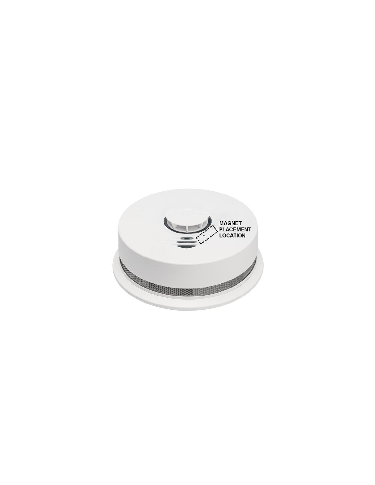
2. Place and hold a magnet for four seconds on the cover of an existing detector in
the network at the designated location per figure 4. The detector will beep once
when the magnet is detected, then the detector will beep twice and the button will
start flashing the RED LED rapidly to indicate the proper mode has been entered
to reset the wireless interconnect settings.
3. Push and hold the test button on any existing detector until two beeps are heard
(approximately four seconds), and then release the button.
• The button-pushed detector will cause the GREEN LED to fade on/off on each
existing detector to signal that the wireless interconnection network has been
opened.
NOTE: From this point, you have fifteen (15) minutes to power up the new
detector.
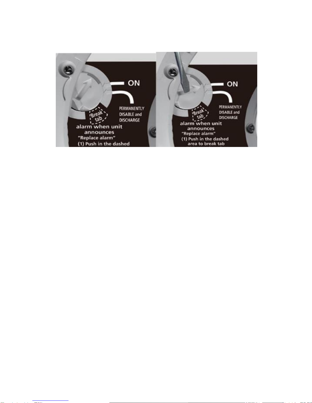
3. Power up the new wireless unit by twisting the detector onto the mounting bracket
(trim plate) to activate the battery, or by carefully turning the activation wheel with a
screwdriver. See Figure 3.
• The new unit's RED LED will fade on/off every three seconds as it searches
for the network.
• A slow GREEN LED fading on/off confirms the new unit has found and joined
the existing wireless interconnection network.
4. Wait fifteen (15) minutes for the network setup to timeout, OR to immediately close
the network, push and hold the test button until two beeps are heard
(approximately four seconds), and then release the button.
• GREEN LED flashes once every 60 seconds on the new detector to indicate
normal operation.
5. After selecting the proper location for your detector, attach the mounting bracket to
the wall or ceiling. To ensure aesthetic alignment of the detector with the hallway,
or wall, the "A" line on the mounting bracket must be parallel with the hallway when
ceiling mounted or horizontal when wall mounted.

7P/N 466-5307 • REV A • ISS 15MAR17 ©2017 United Technologies Corporation
• Install the detector fully on the mounting bracket (trim plate) by rotating the
detector in a clockwise direction. NOTE: The detector will mount to the bracket
in four positions (every 90 degrees).
6. The detector is now activated. After installation / activation, test your alarm as
described in Operation and Testing section.
Resetting a Detector’s Wireless Interconnect Settings
If you experience a delay or problem during wireless interconnection setup, you might
need to start over as if the detector is first removed from its packaging. Also, this "out-
of-box" mode can be used to attempt to reset/clear a network error condition.
1. Place and hold a magnet for 4 seconds on the cover at the designated location per
Figure 4. The detector will chirp once when the magnet is detected, then the
detector will chirp twice and the button will start flashing the RED LED rapidly to
indicate the proper mode has been entered to reset the wireless settings.
Figure 4
2. Press and hold the Test/Hush button for approximately eight seconds while the
RED LED is rapidly flashing. After four seconds, two beeps will occur (do not
release the button). After eight seconds, three beeps will occur. The button can
now be released.
3. Observe two cycles of RED LED on/off, one cycle of GREEN LED on/off
4. The RED LED will begin fading on/off every three seconds.
5. If no further steps are taken within 15 minutes of resetting the detector to "Out-of-
Box" mode, the RED LED will fade on/off for approximately 30-40 seconds, and the
interconnect function will turn off. The detector will then perform as a standard
standalone alarm.

8P/N 466-5307 • REV A • ISS 15MAR17 ©2017 United Technologies Corporation
Enrolling a Detector with a Panel
The following section provides a general guideline for programming (enrolling) the unit
into control panel memory. Refer to the panel documentation for complete
programming details.
1. Set the control panel to into installer programming mode
2. When requested to broadcast a signal from the detector to the panel, remove the
detector from the mounting bracket (trim plate). A tamper message will be
transmitted for smoke, CO, and freeze devices.
3. After waiting approximately 1 minute, reinstall the detector on the mounting bracket
(trim plate). The unit will start chirping rapidly if not re-installed on the trim plate
after 3 minutes.
4. Exit from installer programming mode
NOTE: Each enrollment type (smoke, CO and Freeze) is programmed with a unique
TX ID when manufactured. Labels included on the outside and inside of the packaging
provide these IDs. The unique ID is enrolled into the control panel at the time of
installation. Use these IDs where appropriate in the specific panel being used
enrollment instructions.
Verify programming and unit-to-panel communication
Before mounting, verify that the desired unit location provides good RF communication
to the panel.
To verify programming and RF communication
1. Put the panel into Dealer Sensor Test mode (refer to the specific panel installation
instructions)
2. Take the detector to the desired mounting location.
3. Press and release the Test button. A quick beep will confirm the button has been
pushed.
4. Listen for the appropriate response from system sirens to determine signal integrity
from the unit to the panel (refer to the specific panel installation instructions)
5. Exit from Dealer Sensor Test mode.
Operation and Testing
OPERATION
The smoke alarm takes precedence when both smoke and carbon monoxide are
present.
Smoke/heat alarm pattern is three long beeps, 1.5 seconds pause, three long
beeps, repeating

9P/N 466-5307 • REV A • ISS 15MAR17 ©2017 United Technologies Corporation
Carbon monoxide alarm pattern is four quick beeps repeating every 5 seconds
WARNING: CARBON MONOXIDE ALARM ACTIVATION INDICATES THE
PRESENCE OF CARBON MONOXIDE (CO) AT HIGH CONCENTRATIONS WHICH
CAN KILL YOU.
If the CO condition that caused the alarm in the first place continues, the initiating alarm
unit will reactivate in alarm mode. If the unit goes into alarm mode again within six
minutes, it is sensing high levels of CO which can quickly become a dangerous
situation.
If the CO alarm reactivates within a 24 hour period, call a qualified appliance technician
to investigate sources of CO from fuel burning equipment and appliances, and to
inspect for proper operation of equipment.
If problems are identified during this inspection, have the equipment serviced
immediately. Note any combustion equipment not inspected by the technician and
consult the manufacturer’s instructions, or contact the manufacturer directly for more
information about CO safety and the equipment. Make sure that motor vehicles are not,
or have not been, operating in a garage attached or adjacent to the residence.
The detector is operating once it is activated and testing is complete. When products of
combustion (smoke or CO) are sensed, the unit sounds a loud 85dB alarm. See
Detector Visual and Audible Indicators table. In high levels of CO, the unit will go into
alarm in a shorter period of time than at low levels of CO.
The CO sensor meets the alarm response time as follows:
At 70 PPM, the unit must alarm within 60-240 minutes.
At 150 PPM, the unit must alarm within 10-50 minutes.
At 400 PPM, the unit must alarm within 4-15 minutes.
TESTING (PUSH TO TEST BUTTON)
Test your detector every three months by pressing and releasing the test button
quickly. A quick beep will confirm the button has been pushed.
See Detector Visual and Audible Indicators table. The alarm will sound if the electronic
circuitry, horn, speaker, and battery are working. If the alarm does not sound, the
detector must be replaced.
WARNING: DUE TO THE LOUDNESS (85+ DECIBELS) OF THE ALARM,
ALWAYS STAND AN ARM’S LENGTH (ABOUT 2.5 FT. (0.7M) AWAY FROM THE
UNIT OR USE EAR PROTECTION WHEN TESTING.
Weekly testing is required to ensure proper operation. Erratic or low volume sound (or
no sound) coming from your detector may indicate a defective alarm and it should be

10 P/N 466-5307 • REV A • ISS 15MAR17 ©2017 United Technologies
Corporation
returned for service. See Permanently Disable Detector/Discharge Battery section to
determine how to prepare the unit for shipment or disposal.
WARNING: DO NOT USE AN OPEN FLAME TO TEST YOUR DETECTOR.
YOU COULD DAMAGE THE DETECTOR OR IGNITE COMBUSTIBLE MATERIALS
AND START A STRUCTURE FIRE.
FUNCTIONAL SMOKE TEST
The smoke test verifies that the unit activates when detecting smoke, that the
transmitted signal is received by the receiver/panel, and that the panel reports the
alarm to the central monitoring station. The smoke test should be performed annually.
A canned smoke testing agent must be used for the functional smoke test
NOTE: Use Interlogix brand of Smoke! In A Can part number SM-200.
1. Wait at least 90 seconds after installation to test the smoke detector.
2. Make sure the GREEN LED is flashing for normal operation (one GREEN LED
blink every 60 seconds).
3. From a distance of 2 - 4 feet (0.6 –1.2m), aim spray for 1 –2 seconds at the vents
or side of the detector.
4. The alarm will sound within 1 –10 seconds if the detector functions properly.
5. Press the Test/Hush button to quiet the sounder.
6. Contact the central monitoring station to verify they received the alarm report.
7. Alert the central monitoring station when you are finished testing.
NOTE: An alternative method for performing a functional smoke test in the field is to
hold a smoldering punk or cotton wick close to the detector and direct the smoke into
the vent openings until an alarm is indicated.
CO INSPECTION AND FUNCTIONAL GAS TEST
A canned CO testing agent must be used for the CO functional gas test. Contact a local
supplier for canned CO gas –Solo C6TM CO Detector Tester.
NOTE: Cans of Solo C6TM CO Detector Tester can be sourced from the manufacturer
per the following contact information:
Product Code: Solo C6-024
SDi, 1345 Campus Parkway, Suite A18, Wall Township, NJ 07753 USA
Tel: (732) 751-9266, Fax: (732) 751-9241
1. Wait at least 20 minutes after installation to test the CO detector.

11 P/N 466-5307 • REV A • ISS 15MAR17 ©2017 United Technologies
Corporation
2. Make sure the GREEN LED is flashing for normal operation (one GREEN LED
blink every 60 seconds).
3. Set the control panel to sensor test mode
4. To expedite testing, by-pass the CO accumulator circuit by placing the detector in
“System Test Mode”. Start System Test mode by placing magnet next to reed
switch (Figure 4) and hold it for four seconds until unit chirps twice and the RED
LED begins blinking rapidly.
5. Remove the magnet away from the reed switch.
6. Within 10 second after the magnet is removed press and release Test Button then
within 2 seconds:
7. Press and hold the Test/Hush button until the unit beeps three times
(approximately 8 seconds), and then release the button. The unit will enter the
functional CO Gas test mode within 5 seconds. The GREEN LED will blink
periodically (1 second rate) indicating that the alarm is in functional test mode.
8. Apply UL approved CO test agent to the testing port (Figure 5). When CO is
detected, the unit will activate a CO alarm.
Figure 5
9. To exit functional gas test mode:
a. Press and release the Test button or wait for a two minute timeout.
b. The alarm will reset and then return to normal operating mode.
10. At the control panel, exit sensor test mode.
SMOKE/CO DETECTOR MEMORY
If a detector experiences a smoke or CO alarm event, and then stops alarming, the unit
will give a visual (LED) indicator that a previous alarm has occurred within the last hour.
See the Detector Visual and Audible Indicators table.

12 P/N 466-5307 • REV A • ISS 15MAR17 ©2017 United Technologies
Corporation
AMBIENT LIGHT SENSING
In low light ambient conditions, the GREEN LED will reduce in brightness and intensity.
This detector samples the ambient light conditions of its location and, if possible,
determines a Night/Day cycle. A valid Night/Day cycle will delay the conditions that
require that the detector be replaced (Low Battery or end of Unit Life) or Network Error
chirps at night until the next Day cycle begins. Once the unit goes into End of Unit Life
or Network Error, the chirps can only be silenced by pressing the Test/Hush button.
After 7 days of End of Unit Life chirps, the chirps can no longer be silenced by pressing
the Test/Hush button. Low Battery chirps cannot be silenced. See Troubleshooting
Guide.
WARNING: REPLACE DETECTOR AS SOON AS POSSIBLE WHEN AN END
OF UNIT LIFE OR LOW BATTERY MODE.
If the detector cannot determine a valid Night/Day cycle because the detector is located
in either a constantly dark or lighted location, Low Battery, End of Unit Life, and
Network Error chirps will not be inhibited. If the unit is moved to a location that is not
constantly dark or lighted, it will determine a Night/Day cycle because the unit
continuously samples ambient light conditions.
Detector Visual and Audible Indicators
Operational Mode
Visual Indication
Audible
Indication
Action:
Normal Operation
One GREEN LED
blink every 60
seconds.
None
None
Carbon Monoxide
(CO) Alarm
On all alarming
detectors, the
RED LED blinks
per a Temporal
T4 Pattern
Temporal T4
alarm pattern is
alarm pattern is
four quick blinks
repeating every 5
seconds
On the detector
initiating the CO
Alarm only, the
GREEN LED will
blink every
second.
Alarm per
Temporal T4
Pattern
Temporal T4
alarm pattern is
four quick beeps
repeating every 5
seconds.
Carbon Monoxide has been
detected. Follow the
instructions at the beginning of
this User Guide under the
section "What to do when the
alarm sounds, CO alarm
activation"

13 P/N 466-5307 • REV A • ISS 15MAR17 ©2017 United Technologies
Corporation
Operational Mode
Visual Indication
Audible
Indication
Action:
Smoke/Heat (Fire)
Alarm
On all alarming
detectors, the
RED LED blinks
per a Temporal
T3 Pattern
Temporal T3
alarm pattern is
three long blinks,
1.5 second pause,
three long blinks,
repeating.
On the detector
initiating the
Smoke/Heat
Alarm only, the
GREEN LED will
blink every
second.
Alarm per
Temporal T3
Pattern
Temporal T3
alarm pattern is
three long beeps,
1.5 second pause,
three long beeps,
repeating.
Smoke/fire has been detected.
Follow the instructions at the
beginning of this User Guide
under the section "What to do
when the alarm sounds,
Smoke/Heat alarm activation"
Freeze Warning
One RED LED
blink every 20
seconds.
None
None. Flashing continues
while condition exists.
Tamper Condition
One RED LED
blink every 30
seconds.
Detector chirps
once when
tamper condition
is first sensed,
then the detector
will chirp every 30
seconds after a 3
minute delay.
Reattach detector to its trim
plate, otherwise flashing and
chirping will continue while
condition exists.
Fault Mode/Fatal
Error
One AMBER LED
blink every 5
seconds.
Detector chirps
every 30 seconds.
Flashing/chirping continues
while condition exists.
Remove detector from service.
If fatal error cannot be cleared,
permanently discharge and
decommission the detector.
System Test Mode
Rapidly flashing
RED LED for 10
seconds duration
1 detector chirp
when magnet
detected, 2
detector chirps
when System
Test mode
enabled
Hold magnet next to button for
4 seconds as described in
User Guide.
Local Detector Test
(button press when
no alarm condition
is present)
Flashes RED,
AMBER, GREEN,
then current
protocol
Temporal T3 and
T4 patterns
Allow completion of test or
perform button press to cancel
before end of countdown -
return to normal operation

14 P/N 466-5307 • REV A • ISS 15MAR17 ©2017 United Technologies
Corporation
Operational Mode
Visual Indication
Audible
Indication
Action:
System Detector
Test (button press
in System Mode
when no alarm
condition is
present)
Flashes RED,
AMBER, GREEN,
then current
protocol on each
detector in the
network
Temporal T3 and
T4 patterns
Allow completion of test or
perform button press to cancel
before end of countdown -
return to normal operation
Smoke/Heat or CO
Alarm Memory
(detector has
experienced an
alarm event within
the last hour)
Alternating
flashing RED and
AMBER LEDs. 1
second RED/1
second AMBER/8
seconds OFF,
repeating for 1-
hour
None
Press test button to clear
alarm memory, or allow 1 hour
time out to return to normal
operation. Note - pressing the
test button will
Alarm Nuisance and Hush
This detector is designed to minimize nuisance alarms. Cigarette smoke will not
normally cause the unit to alarm, unless the smoke is blown directly into the detector.
Combustion particles from cooking may set off the alarm if it is located too close to a
cooking appliance. Large quantities of combustible particles are generated from spills
or when broiling. Using the fan on a range hood which vents to the outside (non-
recirculating type) will also help prevent nuisance alarms from occurring by removing
these combustible products from the kitchen.
If the source of a smoke alarm (3 long beeps) is immediately known, you can use the
Hush feature to silence the alarm for approximately 8 - 10 minutes. If no fire is present,
check to see if one of the reasons listed in "Locations to avoid" may have caused the
alarm. If a fire is discovered, get out and call the fire department.
SMART HUSHTM CONTROL AND LOCATE FEATURE
HUSH
The SMART HUSHTM control is extremely useful in a kitchen area or other area prone
to nuisance alarms. The SMART HUSHTM feature has the capability of temporarily
desensitizing the detectors(s) for approximately 8 - 10 minutes. This feature is to be
used only when a known alarm condition, such as smoke from cooking, activates an
alarm. Pushing the Test/Hush button on any initiating detector (GREEN LED flashing
every second), will silence that unit if smoke is not too dense. (In an interconnected
system, all compatible units will also silence.) The smoke alarm will automatically reset
after approximately 8-10 minutes and sound the alarm if particles of combustion are still
present.

15 P/N 466-5307 • REV A • ISS 15MAR17 ©2017 United Technologies
Corporation
LOCATE
This wireless model includes a feature to help you locate the initiating detector(s) in a
wireless interconnect system. During a known smoke alarm event, pushing the
Test/Hush button on any non-initiating detector will silence ALL wireless units EXCEPT
the initiating detectors(s) for two minutes.
After two minutes, all units will resume interconnect alarm if the initiating detector has
not been located and silenced.
NOTE: Depending on detector locations and the location of the smoke source, it is
possible for more than one detector to detect the smoke source and become an
"initiating" alarm unit.
WARNING: THE LOCATE FEATURE CAN BE USED FOR CO ALARM EVENTS
ALSO, BUT IT IS IMPOSSIBLE TO DETERMINE THE SOURCE OF A CO ALARM
USING SIGHT OR SMELL. ALWAYS CONSIDER A CO ALARM EVENT AS
DANGEROUS, AND REMEMBER TO FOLLOW THE STEPS OUTLINED IN THIS
INSTALLATION MANUAL, "WHAT TO DO WHEN THE ALARM SOUNDS, CO
ALARM ACTIVATION".
NOTE: Hush and Locate features are dependent on the type of models enrolled in the
wireless interconnect system. Non-wireless models cannot be enrolled in the wireless
interconnect system and therefore cannot receive the wireless Locate feature; they will
continue to alarm until the initiating unit is Hushed or the Smoke/CO condition clears.
NOTE: The SMART HUSHTM feature and Locate feature can be used repeatedly until
the air has been cleared of the condition causing the alarm.
NOTE: Dense smoke will override the SMART HUSHTM feature and sound a
continuous alarm.
Caution: Before using the alarm SMART HUSHTM feature, identify the source
of the smoke and be certain safe conditions exist.
Battery
NOTE: This detector is powered by a non-replaceable, sealed lithium battery system.
No battery installation or replacement is necessary for the life of the detector.
NOTE: Constant exposure to high or low humidity or temperatures may reduce battery
life.
WARNING: DO NOT ATTEMPT TO OPEN THE DETECTOR FOR ANY
REASON! DO NOT TRY TO REPAIR THE DETECTOR YOURSELF. NO
SERVICEABLE PARTS INCLUDED.

16 P/N 466-5307 • REV A • ISS 15MAR17 ©2017 United Technologies
Corporation
LOW BATTERY
This detector is equipped with a low battery monitor circuit. If the battery capacity can
no longer provide adequate power for all alarm functions, the low battery condition will
occur. See Troubleshooting Guide.
The detector battery must be discharged and the detector must be replaced within 7
days of the first occurrence of the “Low Battery Warning” to provide continuous alarm
protection. Reference the "Permanently Disable Detector/Discharge Battery" section
below for battery discharging instructions.
Permanently Disable Detector/Discharge Battery
WARNING: DISCHARGING THE DETECTOR BATTERY IS PERMANENT.
ONCE THE DETECTOR BATTERY HAS BEEN DISCHARGED, IT CANNOT BE
REACTIVATED!
ONCE DISCHARGED, THE DETECTOR WILL NO LONGER DETECT
SMOKE OR CO.
ONCE THE DETECTOR BATTERY IS DISCHARGED, THE BATTERY IS
DEPLETED AND THE ALARM WILL NO LONGER FUNCTION.
ONCE THE DETECTOR BATTERY HAS BEEN DISCHARGED, THE
DETECTOR CANNOT BE MOUNTED ONTO THE MOUNTING PLATE OR
REACTIVATED.
WARNING: FAILURE TO DISCHARGE ALARM BATTERY AS INSTRUCTED
PRIOR TO DISPOSAL MAY CREATE POTENTIAL FOR LITHIUM BATTERY
RELATED FIRE OR HAZARD.
To Permanently Disable Detector / Discharge Battery:
1. Rotate the detector counterclockwise to remove it from the mounting plate.
2. Push in the dashed area with a screwdriver to break tab.

17 P/N 466-5307 • REV A • ISS 15MAR17 ©2017 United Technologies
Corporation
Figure 6
3. After the tab is broken, use the screwdriver to turn the slotted arrow to the
"Permanently Disable Detector/Discharge Battery" location. This will disable the
detector, stop the low battery or end of unit life “chirps” and render the detector
safe for disposal by draining the battery. Reference FIGURE 6.
Troubleshooting Guide
Trouble Condition
Visual Indication
Audible
Indication
Action:
Fault Mode/Fatal
Error
One AMBER LED
blink every 5
seconds.
Detector chirps
every 30 seconds.
1. Push the Test/Hush button
once to attempt to reset the
detector.
The RED LED will blink out an
Error Code (number of blinks)
when the Test/Hush button is
pushed/released once. Report
the number of blinks to
Customer Service, if needed.
2. Clean your detector. See
Section 12, "Cleaning Your
Detector" for instructions.
Network Error
One AMBER LED
blink every 5
seconds.
Detector chirps
every 30 seconds.
1. Push the Test/Hush button
once to silence the audible
indication for 24 hours at a
time.
The RED LED will blink out an
Error Code (number fo blinks)
when the Test/Hush button is
pushed/released once. Report
the number of blinks to
Customer Service, if needed.
2. Following instructions in
Section 4.3, "Resetting a
Detector’s Wireless Settings",
then attempt to rejoin the
network by following the
instructions in Section 4.2,
"Adding Another Detector to
an Existing Wireless Network
Between Detectors (Wireless
Interconnect)".
*If the error persists, remove,
discharge, and replace the
detector as soon as possible.

18 P/N 466-5307 • REV A • ISS 15MAR17 ©2017 United Technologies
Corporation
Trouble Condition
Visual Indication
Audible
Indication
Action:
Low Battery
One AMBER LED
blink every 5
seconds.
Detector chirps
every 60 seconds.
1. Push the Test/Hush button
once to silence the audible
indication for 24 hours at a
time.
Remove, discharge, then
dispose of detector. Replace
as soon as possible.
End of Detector Life
One AMBER LED
blink every 5
seconds.
Double detector
chirp every 30
seconds.
The RED LED will blink out an
Error Code of 9 blinks. Start of
EOL will be delayed if Night
Detect is active.
Hush (for Low
Battery, Network
Error, End of Life)
One AMBER LED
blink every 5
seconds.
Chirp temporarily
silenced for 24
hours.
Push the Test/Hush button to
initiate Hush.
Sensor Cleanliness
Level (Clean-Me
Indication)
AMBER LED
Clean-Me blink
sequnce after
TESTING (PUSH
TO TEST
BUTTON)
temporal pattern
per Section 5,
"Operation and
Testing"
None
1. Push the Test/Hush button
to initiate detector test.
Following the temporal
patterns, the AMBER LED will
blink the cleanliness status of
the detector:
0-1: Unserviceable fault;
remove, discharge, and
replace the detector.
2-3: Insensitive; requires
cleaning per Section 12,
"Cleaning Your Detector"
4-7: Normal Sensitivity
8-9: Too sensitive, requires
cleaning per Section 12,
"Cleaning Your Detector".
Alarm Fault - # of LED Blinks (short duration blinks)
CO Sensor Test - 2
CO Sensor Short - 4
CO Calibration - 6
Push to Test - 7
Memory - 8
Life Expiration - 9
Smoke Chamber - 10
Interconnect Supervision - 13
Smoke Drift Compensation - 14
Wireless Faults - # of LED Blinks (long duration blinks)
Fault Coordinator - 2
Fault RFD - 3
CCI Supervision - 4
RFD Check In - 5
RFD Time Sync - 6

19 P/N 466-5307 • REV A • ISS 15MAR17 ©2017 United Technologies
Corporation
General Carbon Monoxide (CO) Information
Carbon monoxide (CO) is a colorless, odorless, and tasteless poison gas that can be
fatal when inhaled. CO inhibits the blood's capacity to carry oxygen.
POSSIBLE SOURCES OF CARBON MONOXIDE
Inside your home, appliances used for heating and cooking are the most likely sources
of CO. Vehicles running in attached garages can also produce dangerous levels of CO.
CO can be produced when burning any fossil fuel: gasoline, diesel, propane, natural
gas, oil and wood. It can be produced by any fuel-burning appliance that is
malfunctioning, improperly installed, or not ventilated correctly, such as:
Furnaces/boilers, gas ranges/stoves, gas clothes dryers, water heaters, portable fuel
burning space heaters, fireplaces, wood-burning stoves and certain swimming pool
heaters. Blocked chimneys or flues, back drafting and changes in air pressure,
corroded or disconnected vent pipes, or a loose or cracked furnace heat exchanger can
also release CO into your building. Vehicles and other combustion engines running in
an attached garage and using a charcoal/gas grill or hibachi in an enclosed area are all
possible sources of CO.
The following conditions can result in transient CO situations:
Excessive spillage or reverse venting of fuel-burning appliances caused by outdoor
ambient conditions such as: Wind direction and/or velocity, including high gusts of wind,
heavy air in the vent pipes (cold/humid air with extended periods between cycles),
negative pressure differential resulting from the use of exhaust fans, simultaneous
operation of several fuel-burning appliances competing for limited internal air, vent pipe
connections vibrating loose from clothes dryers, furnaces/boilers, or water heaters,
obstructions in, or unconventional, vent pipe designs which can amplify the above
situations, extended operation of unvented fuel-burning devices (range, oven, fireplace,
etc.), temperature inversions which can trap exhaust gases near the ground, car idling
in an open or closed attached garage, or near a home.
CO SAFETY TIPS
Every year, have the heating system, vents, chimney and flue inspected and cleaned
by a qualified technician. Always install appliances according to manufacturer’s
instructions and adhere to local building codes. Most appliances should be installed by
professionals and inspected after installation. Regularly examine vents and chimneys
for improper connections, visible rust, or stains, and check for cracks in furnace heat
exchangers. Verify that the color of flame is blue on pilot lights and burners. A AMBER
or orange flame is a sign that the fuel is not burning completely and may be releasing
CO. Teach all household members what the alarm sounds like and how to respond.
Fire Departments, most utility companies and HVAC contractors will perform CO
inspections, some may charge for this service. It’s advisable to inquire about any
applicable fees prior to having the service performed. Interlogix will not pay for, or
reimburse the owner or user of this product, for any repair or dispatch calls related to
the alarm sounding.

20 P/N 466-5307 • REV A • ISS 15MAR17 ©2017 United Technologies
Corporation
SYMPTOMS OF CO POISONING
Initial carbon monoxide poisoning symptoms are similar to the flu with no fever and can
include dizziness, severe headaches, nausea, vomiting and disorientation. Everyone is
susceptible but experts agree that unborn babies, pregnant women, senior citizens and
people with heart or respiratory problems are especially vulnerable. If symptoms of
carbon monoxide poisoning are experienced seek medical attention immediately. CO
poisoning can be determined by a carboxyhemoglobin test.
The following symptoms are related to CARBON MONOXIDE POISONING and should
be discussed with ALL members of the household:
1. Mild Exposure: Slight headache, nausea, vomiting, fatigue (often described as
“Flu-like” symptoms).
2. Medium Exposure: Severe throbbing headache, drowsiness, confusion, fast heart
rate.
3. Extreme Exposure: Unconsciousness, convulsions, cardio respiratory failure and
death.
The above levels of exposure relate to healthy adults. Levels differ for those at high
risk. Exposure to high levels of carbon monoxide can be fatal or cause permanent
damage and disabilities. Many cases of reported carbon monoxide poisoning indicate
that while victims are aware they are not feeling well, they become so disoriented they
are unable to save themselves by either exiting the building, or calling for assistance.
Also, young children and household pets may be the first affected. Familiarization with
the effects of each level is important.
Cleaning Your Detector
YOUR DETECTOR SHOULD BE CLEANED AT LEAST ONCE A YEAR
You can clean the detector by using a vacuum cleaner hose and vacuuming through
the openings around the perimeter of the detector. The outside of the detector can be
wiped with a damp cloth. Use only water to dampen the cloth, use of detergents or
cleaners could damage the detector.
If the detector is in fault mode and the RED LED is blinking a fault code of 10 flashes
(after a Test/Hush button push), the detector may be in need of cleaning. After
cleaning, press the Test/Hush button. If the fault does not clear, the alarm needs to be
replaced.
• Never use detergent or other solvents to clean the detector.
• Avoid spraying air freshener, hair spray, or other aerosols near the detector.
• Do not paint the detector. Paint will seal the vents and interfere with the sensor’s
ability to detect smoke and CO.
Table of contents
Other Interlogix Smoke Alarm manuals
Popular Smoke Alarm manuals by other brands

Polon-Alfa
Polon-Alfa DOP-6001R Installation and maintenance manual

Micropack
Micropack FDS300 Safety manual

HIOTH TECHNOLOGY
HIOTH TECHNOLOGY CT-SMZW2007-HM quick start guide

Elkron
Elkron FAP54 installation manual

Faraday
Faraday 8742 installation instructions

Smoke hollow
Smoke hollow SH3616DW owner's manual