Interlogix 60-460-95/NX-495 User manual

P/N 46-547 • REV • October 2012 1
Learn Mode Rate of Rise Heat Sensors
Installation Instructions
Introduction
This is the Learn Mode Rate-of-Rise HeatSensors
Installation Instructions. The sensors (Figure 1) combine a
Chemetron heatdetector and a learn mode wireless
transmitter in one unit. A built-in thermostattrips the transmitter
when the temperature atthe sensor location reaches about
135°F (57°C) or 200°F (94°C), depending on the model
installed.
135°F models
60-460-95/NX-495,60-460-95-LB
200°F models
60-460-01-95/NX-496
Figure 1.Sensor models
Since many fires grow rapidlyin intensitycausing a rapid
temperature increase,the thermostatalso trips the transmitter
if the temperature rises 15°F (8°C) or more per minute.
All models can be powered by one 9-volt alkaline battery that
can last12 to 18 months,or by one 9-volt lithium batterythat
can lastup to twice as long.
Note: Battery life depends on how often the sensor transmits
signals,butis more dependenton the temperature ofthe
installation environment.Alkaline batteries self-discharge more
rapidlywhen used in high temperature environments.
When the battery voltage gets low, the sensortransmits a low
battery signal to the panel.The panel then activates sirens with
trouble beeps to notify the customer that the sensor battery
mustbe replaced
Caution: SX-V Special panels musthave software version 8.0
or later installed for correctresponse from the sensors.Do not
install Learn Mode Rate of Rise Heat sensors ifthe panel an
earliersoftware version.ContactInterlogix technical supportat
888.437.3287 for assistance.
Installation
Use the following installation guidelines:
•Heat sensors should be installed to provide property
protection.Reliance should notbe placed on heat
detectors for life safety. Where life safetyis involved,
smoke sensors mustalso be installed.
•The sensors allow for normal temperature fluctuations,
however, ceiling temperaturesshould notexceed 100°F
(37°C) when installing 135°Fmodels,or 150°F (66°C)
when installing 200°Fmodels.
•Mount the sensor in a central location of the area to be
protected, either on the ceiling or on a wall.
•If mounting on a ceiling,the sensormustbe at least4 in.
(10 cm) away from any walls.
•If mounting on a wall, the top of the sensor mustbe within
4 to 6 in. (10 to 15 cm) of the ceiling.
•The UL maximum spacing allowance ofthe sensor is 50 x
50 ft. (15 x 15 m).Refer to the NFPA Standard 72 for
application requirements.

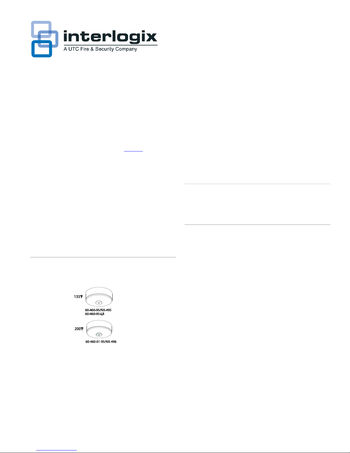
2 LearnMode Rate of Rise Heat Sensors Installation Instructions
•Do not mountthe sensorclose to devices that change
temperature rapidly,such as ovens, heatvents, furnaces,
or boilers.
Equipment needed
You will need the following equipmentto install the sensors:
•Phillips and flathead screwdrivers
•Appropriate learn mode control panel documentation (for
programming information)
Programming
The panel must learn (program) the sensor ID code in order to
respond to sensorsignals.For complete programming
information,refer to the specific control panel documentation.
To add the sensor to panel memory,do the following:
1. Separate the sensor from the base by twisting the sensor
counter-clockwise and pulling the sensor offthe base.Set
the base aside.
2. Place the panel in program mode.
3. Proceed to the Learn Sensors menu.When the panel
prompts you for a sensorgroup number,enter the group
number (26).
4. Select the desired sensor number.
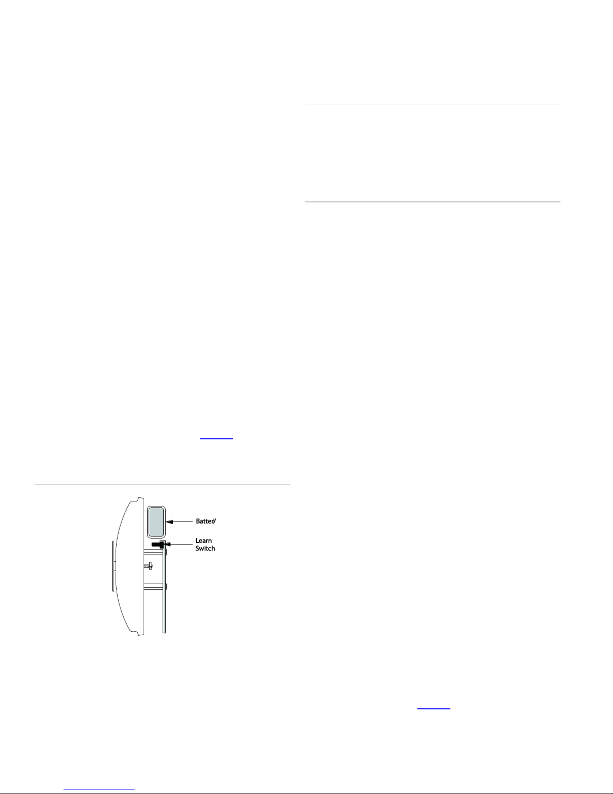
5. When the panel prompts you to trip the sensor,press and
hold the learn switch on the sensor (Figure 2) until the
panel beeps,indicating successful programming.
Figure 2. Learn switch
6. Exit program mode.
Testing
Before permanentlysecuring the sensor to the wall or ceiling,
test the sensor from the installation location using one ofthe
following methods.
Caution: The test method described onlytests rate-of-rise
operation.These sensors cannotbe field tested for their fixed
temperature ratings without being destroyed.When used with
care, the heat from a portable hair dryer (method 2) can be
used for testing.Do not aim the hair dryer directly at the round
disc on the sensor as this can cause itto pop off. If this
happened,the sensor mustbe replaced.
Method 1
To test the sensor,do the following:
1. Place the panel in sensor testmode.
2. Rub your hands together vigorously,until they feel hot.
3. Place the palm of one hand on the round disc of the
sensor,for about7 to 10 seconds.
4. Listen for the appropriate number ofbeeps from interior
sirens and speakers (refer to the specific panel
documentation).
5. Exit sensor test mode.
The sensor should resetin less than one minute.
Method 2
To test the sensor,do the following:
1. Place the panel in sensor testmode.
2. Plug in a portable hair dryer.
3. Hold the hair dryer about12 to 18 in. away from the
sensor,aiming itat the side of the sensor.
4. Listen for the appropriate number ofbeeps from interior
sirens and speakers (refer to the specific panel
documentation).
5. Exit sensor test mode.
The sensor should resetin less than one minute.
Mounting the sensor
To secure the sensor to its permanentlocation,do the
following:
1. Locate the base mounting holes (inner pairand outer pair)
and mountthe base to the wall or ceiling with the
appropriate hardware (Figure 3).
2. Attach the sensorto the base.

Learn Mode Rate of Rise Heat Sensors Installation Instructions 3
Figure 3.Mountingholes
Replacing the batteries
When the sensor batterygets low, the sensor transmits a low
battery signal.The panel receives this signal and sounds
trouble beeps through the system sirens. Pressing the Status
button identifies the sensor with the low battery.
Replace the battery immediatelywhen this condition occurs,
using the following batteries:Eveready©9-Volt Alkaline
Energizer (No. 522);Duracell©9-Volt Alkaline (MN1604); or
UltraLife©9-Volt Lithium.
Battery disposal
Alkaline and lithium batteries thatare not longer usable are
considered hazardouswaste.Be sure to properlydispose of
the old batteries according to your local hazardous waste
disposal laws.
Specifications
Compatibility
Interlogix Learn Mode panels andreceivers
Frequency
319.5 MHz
Pow er requirements
One 9-volt alkaline or lithium battery
Operating temperature
60-460-95/NX495, 60-460-95-LB:
40 to 100°F (4 to 37°C)
60-460-01-95/NX-496:
32 to 150°F (0 to 66°C)
Storage temperature
60-460-95/NX-495, 60-460-95-LB:
-30 to 120°F (-34 to 48°C)
60-460-01-95/NX-496:
-30 to 140°F (-34 to 60°C)
Maximum humidity
90% relative humidity, noncondensing
Dimensions
4.4 in. (11.18 cm) diameter x 2.2 in. (5.59 cm)
depth
Regulatory information
Manufacturer
UTC Fire & Security Americas Corporation,Inc.
1275 Red Fox Rd., Arden Hills, MN 55112-6943,
USA
UL listings
UL 985 Household Fire Warning System Units
UL 521 Heat Detectors for Fire Protective
Signaling Systems
FCC compliance
This device complies w ith part 15 of the FCC
rules for Class A devices. Operationis subject to
the follow ing conditions:
This device may not cause harmful interference.
This device must accept any interference
received, including interference that may cause
undesired operation.
Changes or modifications not expressly approved
by the party responsible for compliance could
void the user’s authority to operate the
equipment.
FCC ID: B4Z-569A-LMRISE
Contact information
For contact information,see www.utcfireandsecurity.com or
www.interlogix.com.
For technical support,toll-free:888.437.3287 in the US
including Alaska, Hawaii,Puerto Rico, and Canada.Outside
the tool-free area, contact your dealer.
© 2012 UTC Fire & Security Americas Corporation,Inc.
Interlogixis part of UTC Climate Controls & Security, a unit of
United Technologies Corporation.
All rights reserved.
This manual suits for next models
2
Table of contents
Other Interlogix Smoke Alarm manuals