manuals.online logo
Brands
  1. Home
  2. •
  3. Brands
  4. •
  5. Intermatic
  6. •
  7. Security Sensor
  8. •
  9. Intermatic EK4000 Series Manual

Intermatic EK4000 Series Manual

• Disconnect power at the circuit breaker(s) or disconnect switch(es)
before beginning installation or servicing.
• Do NOT use the OFF state of the photocontrol for equipment servicing.
Risk of Fire or Electric Shock
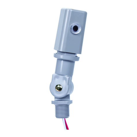
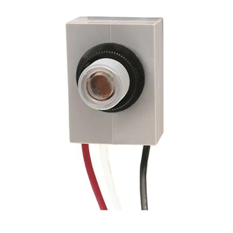
ELECTRONIC PHOTOCONTROL
Installation and Setup Instructions
MODEL EK4000 Series, 347/480 V
NOTICENOTICE
• DO NOT MOUNT WITH THE WIRES FACING UP.
1. Disconnect power before installing.
2. Mount in an approved outdoor junction box or fixture using the included gasket and nut.
(See pictures).
3. DO NOT MOUNT WITH THE WIRES FACING UP.
4. Orient the lens of the photocontrol away from artificial light sources that may cause the load
to turn off at night.
5. See diagram for wiring.
6. Reconnect the power.
7. Test the unit by covering the lens of the photocontrol unit. The photocontrol should react to a
change in less than a minute.
(5 each) Round and Half-round self-adhesive labels for application to photocontrol lens (p/n: LGLBL)
(1) Metal light shield bracket (p/n: 22LG0120) OR (1) plastic light dome (p/n: 6LV1352)
NOTE: Use in case when there is a high amount of incident light on photocontrol from artificial light sources
that may interfere with proper operation of photocontrol.
Installation:
Included Light Shield Accessories:
Wiring Diagram
NUT
GASKET
Photocontrol
Line 1 Load 1
Line 2 / Neutral
orNeutral
(347 VAC)
Line 2
(480 VAC)
White
Red
Black
GASKET
NUT
DIE-CAST PLASTIC
PLASTIC
NUT
LIGHT SHIELD
LABEL
(LGLBL)
LIGHT SHIELD
BRACKET
(22LG0120)
LIGHT SHIELD
DOME
(6LV1352)
GASKET
WARNING
Model Series: EK4x27S EK4x35S
Input Voltage: 347 VAC, 50/60 Hz 480 VAC, 50/60 Hz
Load: 1000 W Tungsten 1000 W Tungsten
1800 VA Ballast 1800 VA Ballast
2 A Electronic Ballast 0.35 A Electronic Ballast*
*Tested with 150 W 480 V LED driver with 120 Apk /100µs In-rush current
Série de modèles: EK4x27S EK4x35S
Tension d’entrée: 347 V CA, 50/60 Hz 480 V CA, 50/60 Hz
Charge: 1000 W Tungstène 1000 W Tungstène
1800 VA Ballast 1800 VA Ballast
2 A Ballast électronique 0.35 A Ballast électronique*
*Testé avec un pilote DEL 150W 480V avec un courant d’appel de 120 Apk/100µs
• Débrancher l’alimentation au niveau des disjoncteurs ou des sectionneurs avant de
procéder à l’installation ou à l’entretien.
• Ne PAS utiliser l’état ARRÊT de la commande photo-électronique pour travailler sur
le matériel.
Risque d’incendie et d’électrocution
COMMANDE PHOTO-ÉLECTRONIQUE
Instructions d’installation et de configuration
MODÈLE SérieEK4000, 347/480 V
AVISAVIS
• NE PAS MONTER AVEC LES FILS VERS LE HAUT.
(par 5) Étiquettes auto-adhésives rondes et demi-rondes à apposer sur la lentille de la commande photo-électronique (réf.: LGLBL)
(1) Support pare-lumière en métal (réf.: 22LG0120) OU (1) dôme pare-lumière en plastique (réf.: 6LV1352)
REMARQUE: Utiliser si la commande photo-électronique est exposée à une grande quantité de lumière incidente provenant de
sources de lumière artificielle susceptibles de nuire à son bon fonctionnement.
Accessoires pare-lumière inclus:
ÉCROU
JOINT
JOINT
ÉCROU
FONTE PLASTIQUE
PLASTIQUE
ÉCROU
ÉTIQUETTE
PARE-LUMIÈRE
(LGLBL)
SUPPORT
PARE-LUMIÈRE
(22LG0120)
DÔME PARE-LU-
MIÈRE
(6LV1352)
JOINT
AVERTISSEMENT Schéma de câblage
Photocontrôle
Ligne 1 Charge 1
Ligne 2 / Neutre
orNeutre
(347 V CA)
Ligne 2
(480 V CA)
Blanc
Rouge
Noir
1. Débrancher l’alimentation électrique avant de procéder à l’installation.
2. Monter dans une boîte de dérivation ou un luminaire homologués pour l’extérieur à l’aide du joint
et de l’écrou fournis (voir les illustrations).
3. NE PAS MONTER AVEC LES FILS VERS LE HAUT.
4. Orienter la lentille de la commande photo-électronique à l’écart de sources de lumière artificielle
susceptible de provoquer l’ouverture du circuit de charge la nuit.
5. Voir le schéma de câblage.
6. Rétablir l’alimentation électrique.
7. Pour vérifier le fonctionnement, couvrir la lentille de la commande photo-électronique. La com-
mande photo-électronique doit réagir à ce changement en moins d’une minute.
Installation:
INTERMATIC INCORPORATED
Libertyville, Illinois 60048 U.S.A.
www.intermatic.com 158--02191
PRINTED IN MEXICO
LIMITED WARRANTY
Warranty service is available by either (a) returning the product to the dealer from whom the unit was purchased or (b) completing a warranty claim online at www.intermatic.com. This warranty is made by:
Intermatic Incorporated, Customer Service 1950 Innovation Way, Suite 300, Libertyville, IL 60048. For warranty service go to: http://www.Intermatic.com or call 815-675-7000.
GARANTIE LIMITÉE
Ce service de garantie est disponible (a) en retournant le produit au vendeur auprès duquel l’unité a été achetée ou (b) en remplissant un formulaire en ligne de réclamation de garantie sur www.intermatic.com.
Cette garantie est faite par : Intermatic Incorporated, Customer Service 1950 Innovation Way, Suite 300, Libertyville, IL 60048. Pour les services de garantie, accédez à la page suivante : http://www.Intermatic.
com ou appelez au 815-675-7000.
GARANTÍA LIMITADA
Este servicio de garantía está disponible mediante (a) la devolución del producto al proveedor al que se le compró la unidad; o (b) el llenado de una reclamación de garantía en línea en www.intermatic.com.
Esta garantía la otorga: Intermatic Incorporated, Customer Service 1950 Innovation Way, Suite 300, Libertyville, IL 60048. Para obtener servicios de garantía, ingrese a: http://www.Intermatic.com o llame al
815-675-7000
Serie de modelos: EK4x27S EK4x35S
Voltaje de entrada: 347 V CA, 50/60 Hz 480 V CA, 50/60 Hz
Carga: 1000 W Tungsteno 1000 W Tungsteno
1800 VA Balasto 1800 VA Balasto
2 A Balasto electrónico 0.35 A Balasto electrónico*
*Probado con controlador LED de 150W 480V, con corriente de irrupción de
120Apk/100µs
• Desconecte el suministro eléctrico de los disyuntores o desconecte los
interruptores antes de comenzar la instalación o el mantenimiento.
• NO use el estado OFF (Apagado) de los controles fotoeléctricos para realizar
mantenimiento del equipo.
Riesgo de incendio o descarga eléctrica
CONTROL FOTOELÉCTRICO
Instalación e instrucciones de configuración
MODELO Serie EK4000, 347/480 V
AVISOAVISO
• NO LO MONTE CON LOS CABLES HACIA ARRIBA.
(Cinco de cada uno) Etiquetas autoadhesivas redondas o en media luna para aplicar en los controles fotoeléctricos (s/n: LGLBL)
(1) Soporte metálico de la pantalla de luz (s/n: 22LG0120) O (1) domo de luz plástico (s/n: 6LV1352)
NOTA: Se debe usar en casos donde hay una gran cantidad de luz incidente en el control fotoeléctrico proveniente de fuentes
de luz artificiales que puedan interferir con el funcionamiento correcto de la unidad.
Instalación:
Accesorios que se incluyen con la pantalla de luz:
Diagrama de cableado
TUERCA
EMPAQUE
Fotocontrol
Línea 1 Carga 1
Línea 2 / Neutral
ONeutral
(347 V CA)
Línea 2
(480 V CA)
Blanco
Rojo
Negro
EMPAQUE
TUERCA
PRESOFUSIÓN PLÁSTICO
PLÁSTICO
TUERCA
ETIQUETA
DE PANTALLA
DE LUZ
(LGLBL)
SOPORTE
DE PANTALLA
DE LUZ
(22LG0120)
DOMO
DE PANTALLA
DE LUZ
(6LV1352)
EMPAQUE
ADVERTENCIA
1. Desconecte la energía eléctrica antes de instalar.
2. Monte en una caja de conexiones o luminaria aprobada para exteriores con el empaque y la
tuerca incluidas. (Consulte las imágenes).
3. NO LO MONTE CON LOS CABLES HACIA ARRIBA.
4. Oriente el lente del control fotoeléctrico lejos de fuentes de luz artificiales que puedan provocar
que la carga se apague por la noche.
5. Consulte el diagrama para ver el cableado.
6. Vuelva a conectar la energía eléctrica.
7. Para probar la unidad, cubra el lente del control fotoeléctrico. Esta debe reaccionar al cambio en
menos de un minuto.

This manual suits for next models

6

Other Intermatic Security Sensor manuals

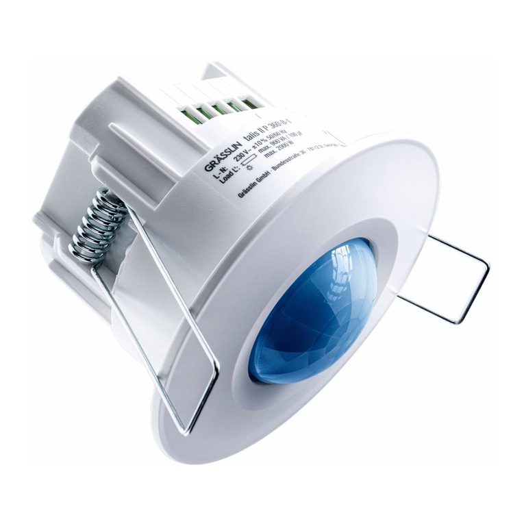
Intermatic Grasslin Talis II P 360-8-1 User manual

Intermatic

Intermatic Grasslin Talis II P 360-8-1 User manual

Intermatic IOS-CMP-DT-U Quick guide

Intermatic

Intermatic IOS-CMP-DT-U Quick guide

Intermatic IOS-DSR User manual

Intermatic

Intermatic IOS-DSR User manual

Intermatic IOS-DDR User manual

Intermatic

Intermatic IOS-DDR User manual

Intermatic EK4000 Series Manual

Intermatic

Intermatic EK4000 Series Manual

Intermatic GRASSLIN talis II PHB 360-20-1i User manual

Intermatic

Intermatic GRASSLIN talis II PHB 360-20-1i User manual

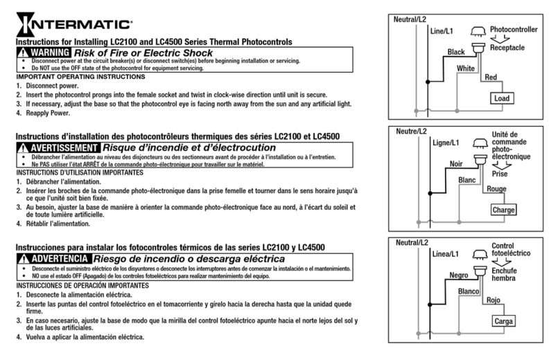
Intermatic LC2100 Series Instruction Manual

Intermatic

Intermatic LC2100 Series Instruction Manual

Intermatic EK4000 Series Manual

Intermatic

Intermatic EK4000 Series Manual

Intermatic IOS-DSIF User manual

Intermatic

Intermatic IOS-DSIF User manual

Intermatic K4000 Series Manual

Intermatic

Intermatic K4000 Series Manual

Intermatic IOS-CMP-DT-LV Quick guide

Intermatic

Intermatic IOS-CMP-DT-LV Quick guide

Intermatic IOS-DOV-NL User manual

Intermatic

Intermatic IOS-DOV-NL User manual

Intermatic IOS-DOV-DT Quick guide

Intermatic

Intermatic IOS-DOV-DT Quick guide

Intermatic IOS-DSIMF User manual

Intermatic

Intermatic IOS-DSIMF User manual

Intermatic IOS-CMP-LV Quick guide

Intermatic

Intermatic IOS-CMP-LV Quick guide

Popular Security Sensor manuals by other brands

SCIEX ExionLC Operator's guide

SCIEX

SCIEX ExionLC Operator's guide

Optex OA-AXIS I Operation manual

Optex

Optex OA-AXIS I Operation manual

teko Astra-9 User instruction

teko

teko Astra-9 User instruction

Techly I-LIGHT-SNR10TY quick start guide

Techly

Techly I-LIGHT-SNR10TY quick start guide

DANLERS CBU-HBWD IP66 quick guide

DANLERS

DANLERS CBU-HBWD IP66 quick guide

Omron F3SP-U3P-TGR user manual

Omron

Omron F3SP-U3P-TGR user manual

Racelogic VBOX quick start guide

Racelogic

Racelogic VBOX quick start guide

Satel AGD-100-BR user manual

Satel

Satel AGD-100-BR user manual

Visonic DUO 220 installation instructions

Visonic

Visonic DUO 220 installation instructions

Bacharach GDC-350 Operation manual

Bacharach

Bacharach GDC-350 Operation manual

EDWARDS SYSTEMS TECHNOLOGY EST3 Operation manual

EDWARDS SYSTEMS TECHNOLOGY

EDWARDS SYSTEMS TECHNOLOGY EST3 Operation manual

Renkforce 1530623 operating instructions

Renkforce

Renkforce 1530623 operating instructions

PCB Piezotronics ICP T356A32 Installation and operating manual

PCB Piezotronics

PCB Piezotronics ICP T356A32 Installation and operating manual

Notifier B710LP installation instructions

Notifier

Notifier B710LP installation instructions

ELRO AS80PR11 installation instructions

ELRO

ELRO AS80PR11 installation instructions

Silverline 466238 manual

Silverline

Silverline 466238 manual

Comelit 8461 Series Technical manual

Comelit

Comelit 8461 Series Technical manual

iMaze Pocket Mate PRODUCT GUIDE AND SAFE USE INSTRUCTIONS

iMaze

iMaze Pocket Mate PRODUCT GUIDE AND SAFE USE INSTRUCTIONS

manuals.online logo
manuals.online logoBrands
  • About & Mission
  • Contact us
  • Privacy Policy
  • Terms and Conditions

Copyright 2025 Manuals.Online. All Rights Reserved.