intermountain AC-12 Guide

HO Scale AC-12 Gear Box Replacement
Instructions
Introduction –
Than you for your purchase of the HO Scale AC-12 from InterMountain
Railway Company. The enclosed gear box it will increase the speed of
your locomotive. Please read all the instructions thoroughly so that you
have a clear understanding of the activities required before beginning. Be
aware that you will be wor ing with very small parts and should have an
area to eep them from getting lost. You will also be removing delicate
details so extra care should be ta en so as to not damage the parts.
Tools required –
• Small flat blade screw driver
• Small Phillips head screw driver
• Locomotive cradle/holder
• Scotch Tape (optional)
The gear box replacement is a multi-part procedure that will require
comfort and s ill wor ing with detailed models. It is recommended that
you ta e your time so as to complete the replacement successfully. The
diagrams are on separate pages from the instructions. Since this process
will involve several small pieces it is recommended that you utilize scotch
tape to attach the small parts to the diagrams as you disassemble the
model. This will insure that parts will not inadvertently get mixed up during
the assembly process.
Should you have questions, please feel free to contact InterMountain
Railway Company for assistance.

Page 2 of 16
Before beginning -
Pre-Step 1:
Separate the tender from the engine by unplugging the 8-pin plug, and
sliding the tender post off of the drawbar.
GEAR BOX REPLACEMENT INSTRUCTIONS
Step 1:
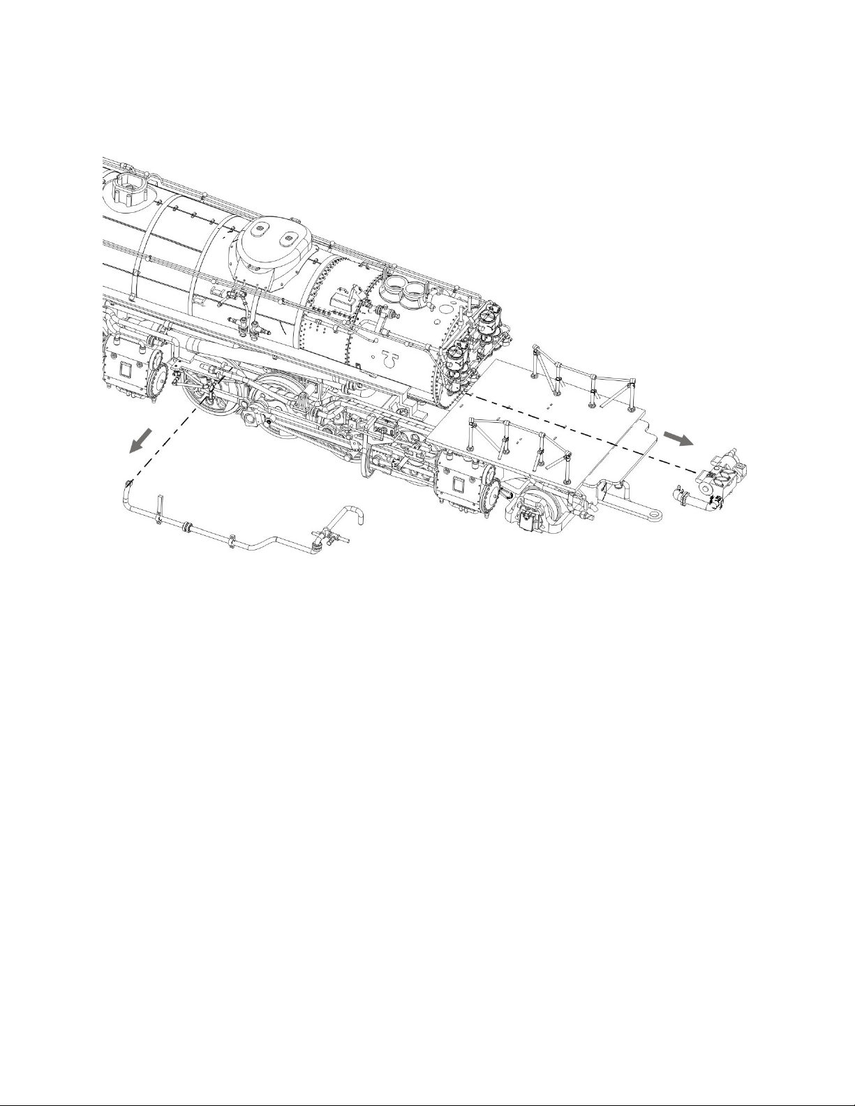
Using a Phillips head screw driver remove the pilot coupler.
Step 2:
Using a Phillips head screw driver remove the two screws holding the cab
in place. These two screws are slightly obscured by under cab details.
(See Figure 1)
Step 3:
Loosen the grab irons from cab doors on each side of the locomotive cab.
Loosen the connecting grab iron from the bac of the cab, below the
window. (See Figure 2)
Step 4:
Loosen the detail piping from the side of the locomotive boiler. There are
details are on both sides that need to be loosened. (See Figure 3)
Step 5:
Remove front generator and connecting piping. The generator is a two
piece item and may come apart. This is not an issue. (See Figure 4)
Step 6:
Remove the boiler caps and steam covers to expose the boiler mounting
screws. Remove the 3 Phillips head screws holding the boiler in place.
(See Figure 5)

Page 3 of 16
Step 7:
Carefully lift the boiler body and cab off the frame. Note that there will be
connecting wiring for the cab lights and printed circuit board. Care should
be ta en not to jer or pull on the wires. The wiring is not shown in the
diagrams. (See Figure 6)
Step 8:
Remove the electrical tape holding the wiring in place along the channels
of the upper weight. This will allow for the boiler body to be moved out of
the way. It will still be connected via the wiring.
Step 9:
Using a Phillips head screw driver, remove the three screws holding the
top weight in place. Lift the weight out of the way, being careful not to pull
or jer on the wiring. (See Figure 7)
Step 10:
Lift the motor out of the frame, removing the drive shaft from the gear box
end, and setting the motor to one side. (See Figure 7)
Step 11:
Remove the five screws holding the frame to drive wheel assemblies. Four
screws from the top and one from the bottom of the frame will need to be
removed. Carefully remove the frame, threading excess pic up wires
through the frame to the wheel pic ups. (See Figure 8)
Step 12:
Remove the worm gear box cover, and drive shaft from the front drive
wheel assembly. (See Figure 9)
Step 13:
Remove the two screws holding the front drive assembly to the gear box
frame. Remove two screws holding the gear box in place and remove the
gear box. (See Figure 10)

Page 4 of 16
Step 14:
Remove worm gear cover from the rear drive wheel assembly. Remove the
worm gear, and replace it with the new worm gear. Replace the worm gear
cover and screw it bac in place. (See Figure 11)
Step 15:
Install the new gear box to the rear drive wheel assembly, and reattach the
rear drive assembly to the front drive assembly. (See Figure 10)
Step 16:
Replace the worm gear in the front drive wheel assembly with the new
worm gear, reattaching the worm gear cover. (See Figure 9)
Step 17:
Reattach the drive wheel assemblies to the frame, carefully threading the
pic up wires through the frame. Once they are fitted bac together screw
in the four screws from the top, and the one screw from the bottom. (See
Figure 8)
Step 18:
Reinstall the motor and drive shaft in the bottom frame, and then place the
top weight on top of the frame. Screw the top weight in place. (See Figure
7)
Step 19:
Realign the wiring into channels of the weight and tape the wires into place
using electrical tape.
Step 20:
Replace the boiler body and cab onto the top of the weight, carefully
aligning the printed circuit board into the slot in front of the weight. Many
details will need to be carefully moved around the boiler while it is being
positioned into place. Care should be ta en not to brea these items. (See
Figure 6)

Page 5 of 16
Step 21:
Screw in the three screws holding the boiler body to the frame and replace
the boilers caps and steam covers. (See Figure 5)
Step 22:
Reattach the front generator and connecting piping. (See Figure 4)
Step 23:
Reattach the detail piping loosened from the locomotive boiler. Details will
need to be reattached on each side. (See Figure 3)
Step 24:
Reattach the grab irons to the cab doors, along witggh the connecting grab
irons on the bac of the cab. (See Figure 2)
Step 25:
Replace the screws holding the cab in place. Reinstall the coupler into the
pilot. (See Figure 1)
At this point you have completed the replacement of the gear box assembly. Test
run you locomotive to validate that everything wor s as desired.

Page 6 of 16
FIGURE 1

Page 7 of 16
Figure 2

Page 8 of 16
Figure 3
Page 9 of 16
Figure 4

Page 10 of 16
Figure 5
Table of contents


