International Biomedical AirBorne 185A+ User manual

185A+ Transport Incubator
Service Manual

I
n
P
h
F
a
E-
M
We
M
a
In
t
8
2
A
u
U
S
A
u
E
m
P
r
2
5
T
h
n
fant
h
one:
(
5
1
a
x: (512)
M
ail: sa
l
e
bsite:
h
a
iling ad
d
t
ernation
2
06 Cros
s
u
stin, TX
S
A
u
thorize
d
m
ergo E
u
r
insesse
g
5
14 AP
h
e Hague
,
Tra
n
with
S
1
2) 873-0
0
873-909
0
l
es@int-
b
h
ttp://ww
w
d
ress:
al Biom
e
s
Park D
r.
78754
d
represe
n
u
rope
g
racht 20
,
The Ne
t
1
n
spo
Opt
i
S
erv
i
0
33
0
b
io.com
w
.int-bio
.
e
dica
l
r.
n
tative i
n
t
herland
s
1
85
A
rt In
c
i
ona
l
i
ce
M
.
com
n
Europe
s
A
+
c
ub
a
l
Pu
l
M
anu
a
for Reg
u
a
tor
S
l
seO
x
al
u
latory A
f
S
yst
e
x
f
fairs:
e
m

TABLE OF CONTENTS
Part No. 715-0078, Rev. B - 1 -
LANGUAGE DISCLAIMER ................................................................................................................... 4
SECTION 1: GENERAL INFORMATION ........................................................................................... 11
INTRODUCTION ....................................................................................................................... 11
CLASSIFICATION .................................................................................................................... 11
SAFETY SUMMARY................................................................................................................. 12
IMPORTANT SAFETY CONSIDERATIONS............................................................................. 12
SYMBOLS................................................................................................................................. 18
SECTION 2: SET-UP INSTRUCTIONS .............................................................................................. 19
MODEL 185A+ UNPACKING AND ASSEMBLY...................................................................... 19
AIR AND OXYGEN TANKS ...................................................................................................... 22
OPERATIONAL CHECK........................................................................................................... 22
SECTION 3: OPERATING INSTRUCTIONS ...................................................................................... 23
FRONT PANEL DISPLAY FEATURES .................................................................................... 23
SIDE PANEL FEATURES......................................................................................................... 28
POWER FEATURES................................................................................................................. 29
POWERING UP THE INCUBATOR .......................................................................................... 31
POWERING OFF THE INCUBATOR........................................................................................ 31
DISPLAY MODES..................................................................................................................... 32
TEMPERATURE CONTROL..................................................................................................... 32
SETTING THE INFANT CHAMBER AIR TEMPERATURE ...................................................... 32
PULSE OXIMETER AND OXYGEN MONITOR CONTROL (OPTIONAL FEATURE).............. 33
ALARMS / INDICATORS.......................................................................................................... 33
EXTERNAL LIGHTING .............................................................................................................36
SKIN TEMPERATURE PROBE ................................................................................................ 36
SECTION 4: PULSE OXIMETRY (OPTIONAL FEATURE)................................................................ 37
PULSE OXIMETER PRINCIPLES OF OPERATION ................................................................ 37
PULSE OXIMETER SET-UP INSTRUCTIONS ......................................................................... 39
INITIAL SET-UP ............................................................................................................. 39
SETTING HIGH AND LOW %SpO2ALARMS ............................................................... 39
SETTING HIGH AND LOW PULSE RATE ALARMS .................................................... 40
SETTING THE ALGORITHM MODE (MASIMO ONLY)................................................. 40
SETTING THE AVERAGING MODE (MASIMO ONLY)................................................. 41
SETTING THE PERFUSION INDEX (MASIMO ONLY) ................................................. 42
OPERATIONAL ALARMS AND WARNINGS........................................................................... 42
TEST OF OPERATIONAL ALARMS ........................................................................................ 44
PULSE OXIMETRY SENSORS ................................................................................................ 44
PULSE OXIMETRY TESTERS / SIMULATORS....................................................................... 45
SECTION 5: OXYGEN MONITOR (OPTIONAL FEATURE) .............................................................. 46
OXYGEN MONITOR PRINCIPLES OF OPERATION............................................................... 46
OXYGEN MONITOR SET-UP INSTRUCTIONS ....................................................................... 47
INITIAL SET-UP ............................................................................................................. 47
SETTING HIGH AND LOW OXYGEN ALARMS............................................................ 47
OXYGEN MONITOR CALIBRATION ............................................................................. 48
OPERATIONAL ALARMS AND WARNINGS........................................................................... 49

TABLE OF CONTENTS
Part No. 715-0078, Rev. B - 2 -
TEST OF OPERATIONAL ALARMS ........................................................................................ 49
OXYGEN SENSOR ................................................................................................................... 50
SECTION 6: PREVENTATIVE MAINTENANCE ................................................................................ 51
DAILY MAINTENANCE ............................................................................................................51
OPERATIONAL CHECK ................................................................................................ 51
AIR / OXYGEN SYSTEM................................................................................................ 52
INFANT CHAMBER CHECK.......................................................................................... 53
CART AND ACCESSORIES .......................................................................................... 53
SENSORS AND CABLES (OPTIONAL EQUIPMENT).................................................. 53
CLEANING OF INCUBATOR AND CHAMBER............................................................. 54
CLEANING OF CABLES (OPTIONAL EQUIPMENT) ................................................... 54
CLEANING OF PULSE OXIMETRY SENSOR (OPTIONAL EQUIPMENT) .................. 54
CLEANING OF OXYGEN SENSOR (OPTIONAL EQUIPMENT)................................... 54
MONTHLY MAINTENANCE ..................................................................................................... 55
OPERATIONAL CHECK ................................................................................................ 55
KEYBOARD / LED CHECK (OPTIONAL FEATURE).................................................... 55
ALARM MUTE CHECK (OPTIONAL FEATURE) .......................................................... 55
TANK INSPECTION ....................................................................................................... 55
INFANT CHAMBER INSPECTION & CLEANING ......................................................... 56
BATTERY TEST............................................................................................................. 56
AIR FLOW SYSTEM INSPECTION & CLEANING ........................................................ 57
HARDWARE .................................................................................................................. 57
BATTERY CARE ...................................................................................................................... 58
PRODUCT DISPOSAL / RECYCLING ..................................................................................... 58
SECTION 7: TROUBLESHOOTING...................................................................................................59
GENERAL TROUBLESHOOTING............................................................................................ 59
MAIN DISPLAY ERROR CODES ............................................................................................. 60
PULSE OXIMETER AND OXYGEN MONITOR FAILURE CODES (OPTIONAL FEATURE) .. 60
SECTION 8: INTERNAL COMPONENT ACCESS ............................................................................. 63
ELECTRONICS COMPARTMENT ACCESS............................................................................ 63
BATTERY REMOVAL...............................................................................................................64
CONTROL BOARD REMOVAL................................................................................................ 64
DISPLAY BOARD REMOVAL .................................................................................................. 65
PULSEOX DISPLAY BOARD REMOVAL ................................................................................ 66
PULSE OXIMETER BOARD REMOVAL .................................................................................. 67
SECTION 9: CALIBRATION PROCEDURES .................................................................................... 68
CALIBRATION TEST EQUIPMENT REQUIRED...................................................................... 68
SYSTEM CALIBRATION PROCEDURE .................................................................................. 68
CONTROL BOARD CALIBRATION PROCEDURE ................................................................. 71
DISPLAY BOARD CALIBRATION PROCEDURE ................................................................... 74
SECTION 10: CIRCUIT DESCRIPTION .............................................................................................75
CONTROL BOARD................................................................................................................... 75
TEMPERATURE REGULATION.................................................................................... 75
FAILSAFE TEMPERATURE LIMIT................................................................................ 76

TABLE OF CONTENTS
Part No. 715-0078, Rev. B - 3 -
ALARMS ........................................................................................................................76
POWER FAIL ALARM ................................................................................................... 77
VOLTAGE REFERENCE ............................................................................................... 77
LAMP DRIVE CIRCUIT .................................................................................................. 77
BATTERY CHARGER.................................................................................................... 78
POWER SOURCE SELECTION..................................................................................... 79
DISPLAY BOARD..................................................................................................................... 79
MEASURED TEMPERATURE DISPLAY....................................................................... 79
MAIN INCUBATOR ALARM AND POWER INDICATORS............................................ 80
TEMPERATURE SETPOINT.......................................................................................... 80
SETPOINT ALARM ........................................................................................................ 80
PULSE, SpO2, AND OXYGEN DISPLAYS (OPTIONAL FEATURES) .......................... 80
SATURATION, PULSE, OXYGEN, AND PULSE GRAPH DISPLAYS (OPTIONAL
FEATURES) ................................................................................................................... 81
ALARM AND POWER INDICATORS (OPTIONAL FEATURES) .................................. 81
ALARM SETPOINTS (OPTIONAL FEATURE).............................................................. 81
SETPOINT ALARM (OPTIONAL FEATURE) ................................................................ 81
OTHER ALARM AND WARNING CONDITIONS........................................................... 81
SECTION 11: SPECIFICATIONS ....................................................................................................... 82
GENERAL MECHANICAL SPECIFICATIONS ......................................................................... 82
ELECTRICAL SPECIFICATIONS............................................................................................. 83
OPERATIONAL SPECIFICATIONS ......................................................................................... 83
EMC SPECIFICATIONS............................................................................................................83
ESSENTIAL PERFORMANCE ................................................................................................. 87
PULSE OXIMETER SPECIFICATIONS (OPTIONAL FEATURE) ............................................ 88
OXYGEN MONITOR SPECIFICATIONS (OPTIONAL FEATURE)........................................... 90
OPERATING, STORAGE, AND TRANSPORT ENVIRONMENT ............................................. 91
SECTION 12: WARRANTY ................................................................................................................ 92
SECTION 13: SYSTEM DOCUMENTATION...................................................................................... 93
EUROPEAN REGULATORY AFFAIRS REPRESENTATIVE .................................................. 93
PARTS AND ACCESSORIES................................................................................................... 93
SECTION 14: SCHEMATICS / DRAWINGS....................................................................................... 94
SYSTEM WIRING DIAGRAM, MASIMO PULSEOX (002-0012) .............................................. 94
SYSTEM WIRING DIAGRAM, NELLCOR PULSEOX (002-0015)............................................ 95
CONTROL BOARD SCHEMATIC (001-5181) .......................................................................... 96
PULSEOX DISPLAY BOARD SCHEMATIC (001-5193) .......................................................... 97
SCHEMATIC, NON-PULSEOX DISPLAY BOARD (001-5192) .............................................. 103
TEMPERATURE SENSOR RESISTANCE VALUES.............................................................. 105
Pa
r
r
t No. 715-00
7
7
8, Rev. B
L
A
A
NGUA
G
G
E DI
S
- 4 -
S
CLAI
M
M
ER
Pa
r
r
t No. 715-00
7
7
8, Rev. B
L
A
A
NGUA
G
G
E DI
S
- 5 -
S
CLAI
M
M
ER
Pa
r
r
t No. 715-00
7
7
8, Rev. B
L
A
A
NGUA
G
G
E DI
S
- 6 -
S
CLAI
M
M
ER
Pa
r
r
t No. 715-00
7
7
8, Rev. B
L
A
A
NGUA
G
G
E DI
S
- 7 -
S
CLAI
M
M
ER
Pa
r
r
t No. 715-00
7
7
8, Rev. B
L
A
A
NGUA
G
G
E DI
S
- 8 -
S
CLAI
M
M
ER
Pa
r
r
t No. 715-00
7
7
8, Rev. B
L
A
A
NGUA
G
G
E DI
S
- 9 -
S
CLAI
M
M
ER
Pa
r
r
t No. 715-00
7
7
8, Rev. B
L
A
A
NGUA
G
G
E DI
S
- 10 -
S
CLAI
M
M
ER

Part No. 715-0078, Rev. B - 11 -
SECTION 1: GENERAL INFORMATION
INTRODUCTION
INDICATIONS FOR USE -
The transport incubator is a neonatal transport incubator. The incubator circulates warmed air at an
operator selected, controlled temperature into a transparent chamber containing an infant. The
structural integrity and weight of the incubator makes it suitable for ground and air transport. Auxiliary
equipment for airway management and vital signs monitoring are not standard equipment. The
system is to be operated by trained medical technical personnel.
The International Biomedical Model 185A+ Infant Transport Incubator with optional PulseOx (referred
to herein as the incubator) provides a thermally regulated environment to support an infant’s
temperature requirements and has the capability to monitor vital information during transport. The
pulse oximeter and oxygen monitor measure pulse rate, oxygen saturation, and oxygen concentration
and allow the user to configure high and low alarm settings. The incubator circulates warmed air
throughout the infant chamber to maintain the temperature at a user-selected setpoint. Chamber
doors and hand ports provide quick and easy access to the infant. Positioning straps are provided to
limit infant movement within the infant chamber. There are no known contraindications associated
with the incubator.
NOTE: The Pulse oximetry and oxygen monitoring is only available if the PulseOx version of the
incubator was purchased.
This service manual is designed to introduce the user to key features of the incubator, including safety
issues, instructions for use, equipment maintenance and contact information. The manual should be
read and understood by all users before using the transport incubator.
CLASSIFICATION
According to the standard EN60601-1 of the International Electrotechnical Commission, Medical
electrical equipment, Part 1: General requirements for safety, the infant transport incubator is classified
as follows:
Class I / Internally Powered, according to the type of protection against electric shock
Type B, according to the degree of protection against electric shock (i.e. the patient may not be
electrically isolated from earth)
Ordinary, according to the degree of protection against harmful ingress of water

SECTION 1: GENERAL INFORMATION
Part No. 715-0078, Rev. B - 12 -
Equipment is not suitable for use in the presence of a flammable anesthetic mixture with air or
with oxygen or nitric oxide.
Continuous operation for the mode of operation
The pulse oximeter cables and sensors are classified as type BF, per the EN60601-1 electrical
standard.
The skin temperature probe is classified as type BF, per EN60601-1 electrical standard (systems with
optional PulseOx).
The skin temperature probe is classified as type B, per EN60601-1 electrical standard (systems
without optional PulseOx).
SAFETY SUMMARY
The incubator is designed to be used by trained clinical users and/or biomedical engineers and
operated in a manner consistent with the instructions contained in this manual. Refer to any additional
training, procedures, requirements, or documentation beyond those identified here for operation and
policies required within the institution. All personnel operating the incubator must be familiar with the
warnings and operating procedures contained in this manual. International Biomedical is not to be
held responsible if the incubator is used in a manner inconsistent with the instructions herein.
IMPORTANT SAFETY CONSIDERATIONS
The incubator has been tested and found to comply with limits for electromagnetic interference and
susceptibility as defined by EN60601-1-2. However, this equipment can radiate radio frequency (RF)
energy and may cause harmful interference to other devices. The incubator may also be affected by
interference from other devices. If RF interference is suspected, relocate or shield the incubator to
reduce or eliminate the effects.
Within certain governmental jurisdictions, all interconnected accessory equipment must be labeled by
an approved testing laboratory. After interconnection with accessory equipment, risk (leakage) current
and grounding requirements must be maintained.

SECTION 1: GENERAL INFORMATION
Part No. 715-0078, Rev. B - 13 -
Safety concerns or additional pertinent information will be displayed using warnings, cautions, and
notes, having the following significance:
WARNING: Maintenance or operating procedure, technique, etc., which may result
in personal injury or loss of life if not carefully followed.
CAUTION: Maintenance or operating procedure, technique, etc., which may result in
patient harm or damage to equipment if not carefully followed.
NOTE: Maintenance or operating procedure, technique, etc., which is considered
essential to emphasize.
The principal WARNING and CAUTION notices to be observed in use of this incubator are brought
together here for emphasis.
WARNINGS
OBSERVE BEST PRACTICE: The instructions in this manual in no way supersede established
medical procedures or staff preference concerning patient care.
ENSURE UNIT IS PROPERLY GROUNDED: To ensure grounding reliability, only connect the
power cord to a properly grounded, 3-wire hospital grade outlet of the proper voltage and
frequency. DO NOT USE EXTENSION CORDS. If the integrity of the connection is in doubt,
the incubator should be operated from its internal battery.
EXPLOSION HAZARD: Do not use the examination light, the pulse oximeter, or oxygen
monitor in the presence of flammable anesthetics or other flammable gases.
USE OF OXYGEN INCREASES FIRE DANGER: Spark-producing auxiliary equipment should
not be placed in or near the transport incubator.
Avoid direct sunlight or radiant heat, which can cause a dangerous increase in chamber air
temperature.
Avoid eye exposure. Direct light exposure may cause eye damage. Infants must wear eye
protection.
The use of oxygen may increase the noise level within the infant chamber.
Air and oxygen tanks are pressurized and must be properly secured.

SECTION 1: GENERAL INFORMATION
Part No. 715-0078, Rev. B - 14 -
The transport incubator is Type B equipment and the baby may not be electrically isolated from
earth. Care must be taken that additional equipment connected to the baby is electrically safe.
To ensure patient electrical isolation, connect only to other equipment with electronically
isolated circuits.
Do not change the lamp and touch the patient simultaneously.
When the infant tray is removed, do not touch exposed circuitry and patient simultaneously.
This incubator was calibrated with the infant chamber originally supplied. If this chamber is
exchanged for an infant chamber of a different configuration or size, the temperature calibration
will be affected. Consult International Biomedical before returning the incubator to service.
The incubator should be turned off and AC or DC power disconnected when cleaning.
The use of devices which radiate high intensity electrical fields may affect the operation of the
transport incubator. Constant assessment of the patient and all life support equipment is
mandatory whenever interfering devices are operating on or near patient.
When using the transport incubator adjacent to or stacked with other equipment, observe the
operation of the transport incubator and the other equipment to ensure normal operation.
Portable RF communications equipment (including peripherals such as antenna cables and
external antennas) should be used no closer then 30 cm to any part of the transport incubator
and associated cables. Otherwise, degradation of the performance of this equipment could
occur.
When the incubator is attached to a Ferno 146 Collapsible Cart, the two highest positions
should not be used as they can cause a tip hazard.
Do not use the pulse oximeter or oximetry sensors during magnetic resonance imaging (MRI)
scanning. Induced current could potentially cause burns. The pulse oximeter may affect the
MRI image and the MRI unit may affect the accuracy of the oximetry results.
If using pulse oximetry during full body irradiation, keep the sensor out of the irradiation field. If
the sensor is exposed to irradiation, the reading might be inaccurate or the unit might read zero
for the duration of the active irradiation period.
The pulse oximeter should NOT be used as an apnea monitor.

SECTION 1: GENERAL INFORMATION
Part No. 715-0078, Rev. B - 15 -
If an alarm condition (other than exceptions listed herein) occurs while the MUTE button is
activated, only visual alarm indicators will be activated.
Pulse rate measurement is based on the optical detection of a peripheral flow pulse and
therefore may not detect arrhythmias. The pulse oximeter should not be used as a replacement
or substitute for ECG based arrhythmia analysis.
Connecting equipment to the outlets on this device creates a medical electrical system and the
user is responsible for continued compliance with the requirements of IEC 60601-1.
Do not modify this equipment without proper authorization from International Biomedical.
An Infant Transport Incubator should be used by appropriately trained personnel and under the
direction of qualified medical staff familiar with currently known risks and benefits of Infant
Transport Incubator use.
When this incubator is operated on battery in low ambient temperatures, the thermal cover must
be used.
Skin temperature probe is not a rectal probe. The skin temperature sensor is not to be used as
a rectal probe.
Do not use liquids in or around the transport incubator.
CAUTIONS
U. S. Federal and Canadian law restricts this device to sale by or on the order of a physician or
other licensed medical practitioner. Outside Canada and the U. S., check with local laws for
applicable restrictions.
Use of sharp objects on Front Display Panel will cause permanent damage and will void
warranty.
Do not touch, press, or rub the display panels with abrasive cleaning compounds, instruments,
brushes, rough-surface materials, or bring them into contact with anything that could scratch the
panel.
Use an oxygen analyzer when oxygen is delivered to the infant.
The incubator electronics contain static sensitive components that can be damaged by improper
handling. Use approved grounding techniques for work areas and service personnel.
The infant tray grounding tabs are sharp; use care when cleaning air flow system.

SECTION 1: GENERAL INFORMATION
Part No. 715-0078, Rev. B - 16 -
Do not move the incubator by pushing on the infant chamber. The infant chamber is not
designed to sustain the forces to push the incubator. Stress fractures in the infant chamber can
occur.
DO NOT leave the 12 volt cord attached to the DC connector of the incubator.
Do not overtighten the infant chamber screws. Do not strip the aluminum into which these
screws are threaded.
Do not drip cleaning solution through the holes where the swell latches fit into the air flow
assembly.
The incubator MUST be plugged into AC power and the battery recharged after any battery
usage. The battery will sustain damage if drained of power and not placed on recharge soon.
CLEANING AND CARE: Do not autoclave, pressure sterilize, or gas sterilize the incubator,
cables, or sensors. Use cleaning solutions sparingly as excessive solution can flow into the
incubator and cause damage to internal components. Do not soak or immerse the incubator or
sensors in any liquid. Do not use petroleum-based, alcohol, acetone, or other harsh solvents.
See cleaning instructions of reusable sensors and cables in directions for their use.
Check alarm limits each time the system is used to ensure that they are appropriate for the
patient being monitored.
Use only parts, accessories, transducers, and cables designated by International Biomedical for
use with the transport incubator. Cables and accessories other than those supplied by
International Biomedical may result in unacceptable operation of the transport incubator and will
void the equipment warranty.
If a sensor or cable is damaged in any way, discontinue use immediately.
The Maxtec MAX-250E oxygen sensor is a sealed device containing a mild acid electrolyte,
lead (Pb), and lead acetate. Lead and lead acetate are hazardous waste constituents and
should be disposed of properly, or returned to Maxtec or International Biomedical for proper
disposal or recovery.
Pulse oximeter probes and cables are designed for use with specific monitors. Only use
Masimo sensors and patient cables for Masimo pulse oximetry model. Only use Nellcor
sensors and patient cables for Nellcor pulse oximetry model. Verify the compatibility of the
monitor, sensor, and cable before use, otherwise patient injury can result.

SECTION 1: GENERAL INFORMATION
Part No. 715-0078, Rev. B - 17 -
Only use International Biomedical cable and Maxtec sensor for oxygen monitoring.
Calibrate the oxygen sensor daily when in use or if environmental conditions change
significantly (i.e., Temperature, Humidity or Barometric Pressure).
Dropping or severely jarring the oxygen sensor after calibration may shift the calibration point
enough to require recalibration.
Oxygen sensor and pulse oximetry cables must be contained within cart or otherwise secured
when not in use.
S
Pa
r
S
Y
T
h
re
c
8
7
ECTIO
N
r
t No. 715-00
7
Y
MBO
L
h
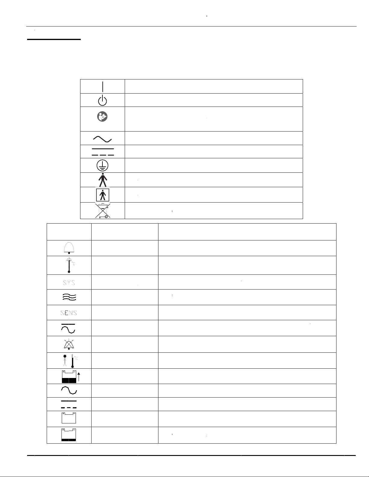
e followin
g
c
ognized s
y
7
8.
SYM
N
1: G
E
7
8, Rev. B
L
S
g
symbols
a
y
mbols are
(Blue Ba
c
BOL
R
H
S
P
B
E
NER
A
a
ppear in t
h
defined b
y
On
Off
kground)
A
tt
e
A
lt
e
Dir
e
Pro
t
Ty
p
Ty
p
Re
c
MANUA
L
R
EFEREN
C
A
LAR
M
H
IGH TE
SYS F
A
A
IR FL
O
S
ENS F
A
P
WR F
A
MUT
E
ABY TE
BAT C
H
A
C O
P
DC O
P
BAT O
P
LOW B
A
A
L INF
O
h
e incubato
r
y
the Intern
a
(power: conn
(Standby)
e
ntion, consul
e
rnating Curr
e
e
ct Current
t
ective earth
p
e B equipme
p
e BF equipm
c
ycle or disp
o
L
C
E
M
Des
M
P
Hig
h
A
IL
Sys
t
O
Air
f
A
IL
Pri
m
A
IL
Inc
u
bel
o
E
Mut
e
MP
Bab
H
G
Batt
P
Inc
u
P
Inc
u
P
Inc
u
con
n
A
T
Lo
w
O
RMA
T
- 18 -
r
documen
t
a
tional Ele
c
ection to the
t accompany
e
n
t
(
ground)
n
t (EN60601
-
ent (EN6060
1
o
se of properl
y
ignates locat
i
h
temperatur
e
t
em failure al
a
f
low blockag
e
m
ary tempera
t
u
bator not co
n
o
w 10.1 volts
e
button sile
n
y probe tem
p
ery charging
u
bator conne
c
u
bator conne
c
u
bator operati
n
ected
w
battery indic
T
ION
t
ation and l
c
trotechnic
a
mains)
y
ing documen
-
1)
1-1)
y
, contains s
e
EXPL
A
ion of alarms
e
alarm indic
a
a
rm indicato
r
e
alarm indic
a
t
ure sensor
m
n
nected to A
C
n
ces audible
a
p
erature mod
e
indicator
c
ted to AC p
o
c
ted to DC p
o
ng on intern
a
c
ator
abels. Th
e
a
l Commis
s
ts
e
aled lead b
a
A
NATION
on front pan
e
a
tor
r
a
tor
m
alfunction al
C
nor DC, an
d
a
larms for ap
p
e
o
wer
o
wer
a
l battery due
e
se interna
t
s
ion, IEC 4
a
tteries
e
l
arm indicato
r
d
battery po
w
p
roximately 1
to no extern
a
t
ionally
17A and I
E
r
w
er is
minute
a
l power
E
C
Table of contents
Other International Biomedical Accessories manuals


