Introduction
Thank you for purchasing the Hioki Z2018, Z2019 Heat Flow Sensor. To obtain maximum performance from the product over the long term,
be sure to read this manual carefully and keep it handy for future reference.
(This sensor is calibrated by DENSO CORPORATION.)
Verifying Package Contents
When you receive the product, inspect it carefully to ensure that no damage occurred during shipping. If damage is evident, or if it fails to
operate according to the specications, contact your authorized Hioki distributor or reseller. For information about package contents, see
Accessories listed in Specications.
Operating Precautions
• Before use, verify that there is no wiring break in each of the heat ow wires and the temperature wires between the positive and the
negative terminals. A resistance value of 2 kΩ or less between the terminals indicates that there is no wiring break. Although the resistance
value between the terminals may increase depending on the environment, a resistance value of 2 kΩ or less will not have any effect on any
output values.
• Each sensor has a different sensitivity value.
• To clean the sensor, wipe it gently with a soft cloth moistened with water.
• Do not subject the sensor to excessive force during use or storage.
• The cable may harden during use at temperatures of 0°C or lower.
• As a result of the sensor’s excellent response characteristics, measured values may uctuate due to factors such as outdoor airow and
radiant heat in the surrounding environment. To minimize such uctuations, see “Limiting measured value uctuations” below.
• Although the sensor is waterproof, its tip is not. Exposure of the tip to water droplets may result in rust, malfunction, or failure. Exercise care
to avoid exposing the tip of the sensor to water droplets.
• In environments in which the sensor is exposed to sunlight and other radiation, output values will include the radiant heat component.
• The lettering on the mark tubes will fade if subjected to strong rubbing or placed in direct sunlight for an extended period of time. Protect the
mark tubes as necessary.
• Repair service for this sensor, which is consumable, is not offered.
Affixing the Sensor to the Measurement Target
Secure the sensor so as to keep out any foreign materials or air layer by using Model Z5008 Thermally Conductive Tape. If an object with
thermal resistance comes between the sensor and measurement target, it will be impossible to obtain accurate measured values for heat
ows.
Do not reuse the double-sided tape. If the double-sided tape is reused, it will be impossible to obtain accurate measured values.
You will need: the sensor and Model Z5008 Thermally Conductive Tape (option)
1
Cut the thermally conductive tape to the necessary size and remove the protective backing.
(Apply another piece of tape over the exible part to secure it, when necessary)
2
Apply the thermally conductive tape to the measurement target and remove the lm on the opposite side.
3
Apply the entire back side of the sensor (the side with the at surface) to the thermally conductive tape.
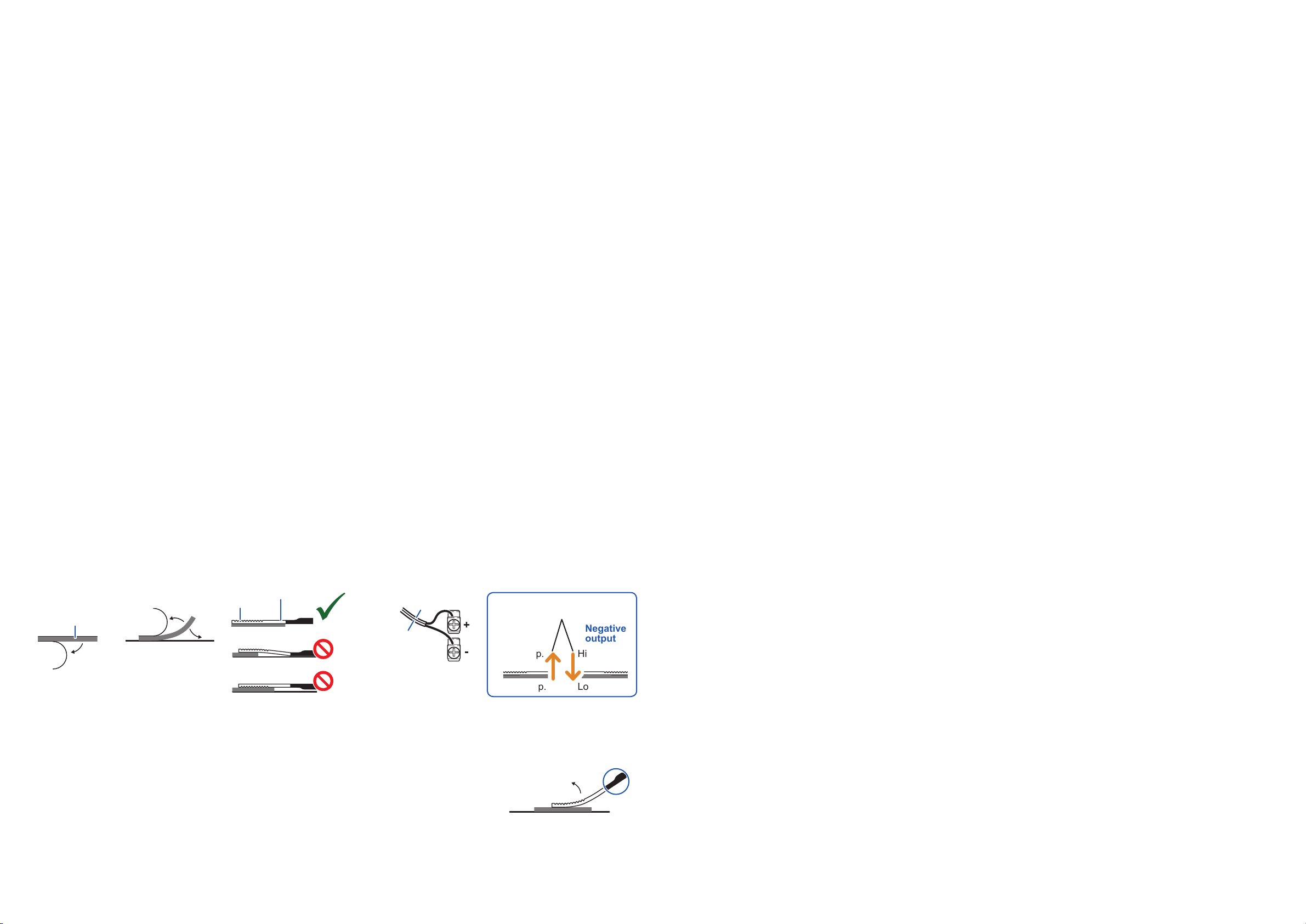
4
Connect the sensor’s red wire (+) to the host device’s positive terminal and the sensor’s white (−) wire to the host device’s negative
terminal. (The voltage output from the sensor will vary with the direction in which the heat flows. If you wish to reverse the output,
reverse the sensor’s terminal connections.).
Negative
output
1
Protective
backing
Thermally
conductive
tape
2 3 4
Measurement
target
Sensor
OK
Lower temp.
Higher temp.
Higher temp.
Lower temp.
Heat transfer
NO
NO
Positive
output
FRONT Heat ow output
Red (+)
White (-)
When making measurements over an extended period of time or in an environment where the sensor will be subjected to vibration, secure
the cable in place, for example with tape, so that there is no load applied on the sensor, flexible part, and cable. If affixing the sensor to a
curved surface, secure the sensor’s tip and the flexible part's tip in place with tape that is no thicker than 50 μm.
Removing the Sensor From the Measurement Target
Grip the cable near the exible part and lift up slowly from the tip to peel off the sensor.
(Bending the sensor or the flexible part excessively or peeling it off violently will subject it to excessive force,
causing it to malfunction or fail.)
Limiting Measured Value Fluctuations
Using the LR8432’s waveform calculation moving average function
This function enables you to simultaneously record the actual input waveform and a waveform obtained by applying a lter to eliminate
uctuations. For more information, see the LR8432 instruction manual.
EN Test Equipment Depot - 800.517.8431 - 99 Washington Street Melrose, MA 02176
TestEquipmentDepot.com


