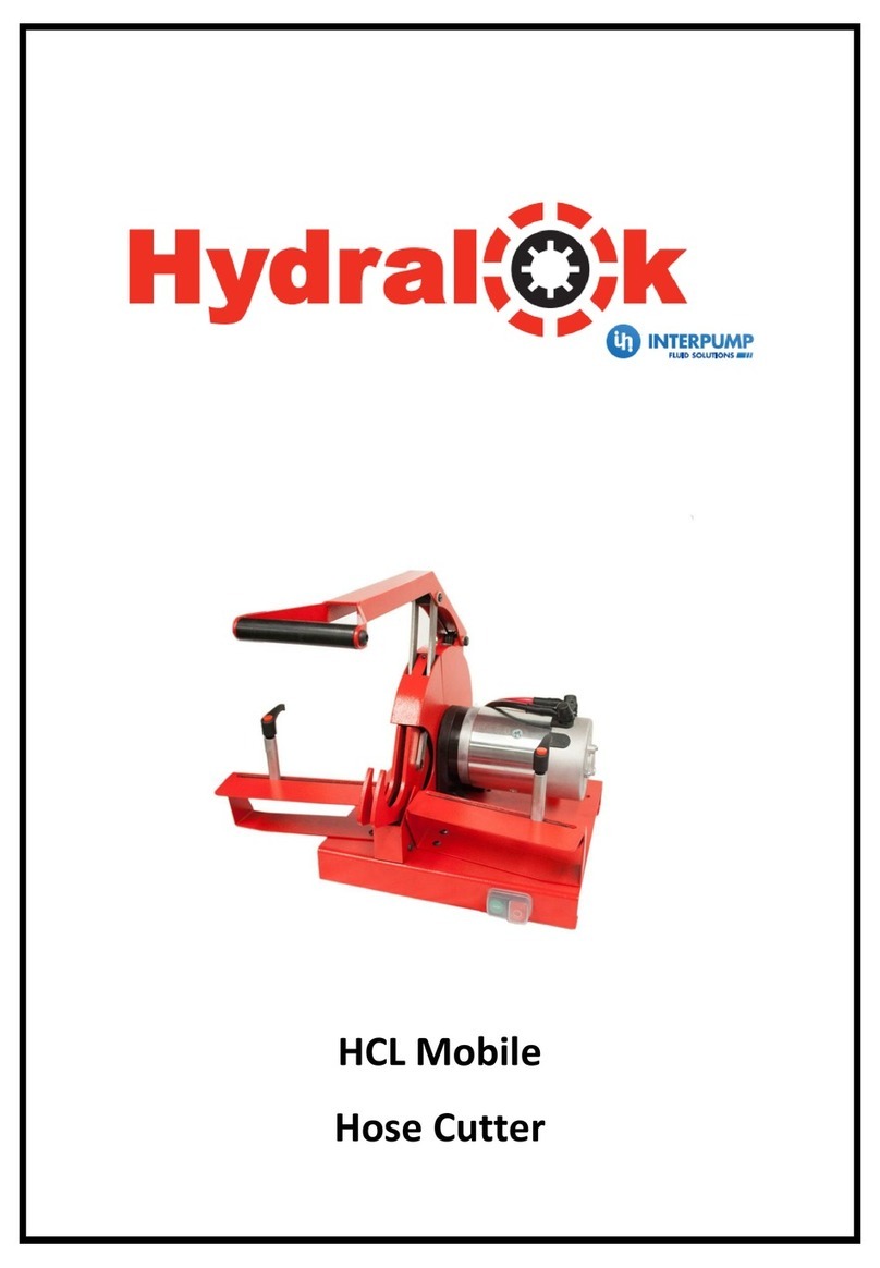
Interpump Hydralok HCLMOBILE User manual

USER MANUAL
Electric hose cutting machine
HCLMOBILE

2
SOMMARIO
WARRANTY CONDITIONS.................................................................................................3
DECLARATION OF CONFORMITY ....................................................................................4
SAFETY REGULATIONS....................................................................................................5
TECHNICAL / DIMENSIONAL DATA ..................................................................................6
HANDLING/TRANSPORT...................................................................................................6
INSTALLATION...................................................................................................................6
PRELIMINARY CHECKS.....................................................................................................7
LIGHTING............................................................................................................................7
ROUTINE MAINTENANCE..................................................................................................7
MACHINE DESCRIPTION...................................................................................................7
OPERATING INSTRUCTIONS............................................................................................7
MAINTENANCE AND SERVICE .........................................................................................8
GUIDELINES FOR CORRECTING CUT.............................................................................8
BLADE WEAR.....................................................................................................................8
REPLACEMENT BLADES...................................................................................................8
Appendix 1 –Mounting Information .....................................................................................9
Appendix 2 –Wiring Schematic.........................................................................................10
Appendix 3 –Machine Diagram.........................................................................................11
Appendix 4 –Blade Replacement Instructions ..................................................................13
SPARE PARTS..................................................................................................................16

3
WARRANTY CONDITIONS
1. Note that all machines undergo strict testing before shipment.
2. All machines are warranted against any defects for a period of 12 MONTHS starting
from the date of delivery to the customer. The company reserves the right to require
a copy of the sales invoice.
3. We must verify defects. Therefore, each defective item must be returned to our
address with SHIPPING CHARGES PREPAID. We will return the item with
CARRIAGE FORWARD. ANY DELIVERIES TO OUR COMPANY WITH
CARRIAGE FORWARD WILL BE SENT BACK TO THE SENDER.
4. This warranty covers replacement and repair of any component found to be
defective.
5. Replacements and repairs completed under this warranty cannot extend its 12
months validity.
6. This warranty does not cover any damages caused by deterioration from use.
7. This warranty is not valid for damage resulting from incorrect operation or use not in
compliance with the machine instructions.
8. This warranty is not valid in case of unauthorized machine modification.
9. This Instruction Manual is also to be considered as a warranty certificate, with
validity commencing from the date indicated on the freight bill.
GENERAL SALES TERMS AND CONDITIONS
For general sales terms and conditions, always refer to the catalogue Technical data -
General sales terms and conditions, page 59.

4
DECLARATION OF CONFORMITY
(according to current EC legislation)
the subscribed: I.M.M. Hydraulics S.p.A.
registered office in: Via Italia 49, 51
66041 ATESSA
VAT and fiscal Code 01427010697
in the person of Marcello Di Campli
declares:
Model: HCLMOBILE
Construction Year: 2019
Serial Number:
Description: Electric hose cutting machine
The machine is not included in the list of the Annex IV of Machinery Directive 2006/42/CE.
The machine complies with the requirements of Machinery Directive 2006/42/CE
Also declares complying with the following regulations:
CEI –EN 60204-1:2006-09 (Safety of machinery –Electrical equipment of machines).
2014/35/UE (Low Voltage Directive),
2014/30/UE (Electromagnetic compatibility (EMC) Directive).
Atessa, 15/01/2019 Signed

5
SAFETY REGULATIONS
Always work in safe conditions and with the necessary space around the machine. Ensure
that the machine is placed on a stable and appropriate working surface.
1. DO NOT USE the equipment before reading the user manual.
2. CAUTION! If improperly used, the equipment may be dangerous and may cause
injury. Do not touch any moving parts.
3. CAUTION! It is absolutely essential that all working operations are carried out by
one operator only
4. This manual must be provided for the machine operator. Ensure that the operator is
aware of his/her responsibilities.
5. Guards must never be removed or tampered with.
6. (Where applicable) A fully trained and competent electrician must connect the
machine to the appropriate electricity supply.
7. Always wear protective gloves, safety glasses and appropriate clothing.
8. (Where applicable) Disconnect the power supply before removing any covers, or
attempting any maintenance of the machine
9. Only original spare parts can be used in the maintenance of the machine.

6
TECHNICAL / DIMENSIONAL DATA
TECHNICAL/DIMENSIONAL DATA
HCL MOBILE
Capacity
3/16” -1 1/2”
R1AT/1SN/R2AT/2SN (2 wire)
3/16” -1 1/4” R9R/4SP (4 wire)
Motor [Kw]
1.8
Dimensions [mm]
Ø 250x3
Gross Weight [kg]
29
Volts [V]
12 / 24 VDC
Noise level
< 75 dB
HANDLING/TRANSPORT
The machine will normally be shipped bolted to a wooden pallet. The bolts should be
removed and the machine lifted onto the work place using suitable lifting equipment.
INSTALLATION
The machine must be fixed to a firm, and level work surface, bolted down by a minimum of
twobolts located in opposing corners of the machine. Mounting information can be found in
Appendix 1–Mounting Information.
Connections should be made to an appropriate 12v / 24v DC electrical supply by a
qualified electrician. Standard wire colour coding is applied where the RED wire terminal
must be connected to the positive/live supply terminal, and the BLACK wire must be
connected to the negative/neutral supply terminal. For electrical schematic see Appendix 2
–Wiring Schematic.
A separate 160 ‐180 amp battery coupled to a split charger is recommended. Alternatively
a 110 ‐120 amp battery can be used for light duty. To ensure a maximum 12 volt DC
supply is delivered to the machine, a minimum cable size of 25 mm square with a
maximum length of four meters can be fitted. A suitable isolator and overload protection
device should be fitted to the voltage supply line.
Prior to operation, ensure that the blade is free to rotate without fouling on any of the
guards and that the guards are operating correctly and covering the cutting blade
completely.

7
PRELIMINARY CHECKS
Place the machine on a stable surface. Where applicable, ensure that the power supply
line is fitted with a differential safety breaker and overload cutout.
LIGHTING
The equipment does not have its own lighting and so it must be used in a suitably
illuminated area.
ROUTINE MAINTENANCE
Regular inspection of the guards must be carried out and under no circumstances must
the machine be operated with damaged or inactive guarding.
The cutting blade should be regularly inspected for damage and lose of cutting
performance. A damaged blade must NOT be used. Where the machine is in constant use
a daily check is recommended. If the blade is damaged or the cutting performance is
reduced the blade will need replacing (or regrinding).
MACHINE DESCRIPTION
A bench mounted, electrically powered rotating circular, toothed knife. Cutting operation is
powered by hand. The machine is intended to be used for cutting steel wire reinforced
rubber hydraulic hose or similar.
OPERATING INSTRUCTIONS
To move the hose support pillars (object 4 of Appendix 3 –Machine Diagram), unscrew
the clamping handle 1‐2 rotations, slide the pillar to position, and re‐tighten the clamping
handle. Set the hose support pillars an equal distance apart from the blade, so that when
the handle (1) is pushed down the hose is put under reasonable bending strain to relieve
pressure on the sides of the blade during the cutting operation.
Place the hose into the cutting jaws (6) so that the hose bends out towards the user and is
supported by the hose support pillars (4). Ensure that the cutting mark is directly between
the hose cutting jaws (6). Switch on the machine using the green portion of the control
button (3) and push the handle downwards SLOWLY.
Allow the blade to cut through the hose at a controlled rate without excessive slowing of
the blade. When the hose is cut, allow the handle to return to a fully up position where the
blade is fully covered and switch off the machine using the red portion of the control button
(3).

8
MAINTENANCE AND SERVICE
Regular inspection and routine cleaning of the machine, focussing especially on the guards
(Appendix 3 ‐7 & 8). Under no circumstances should the machine be used if the guards have been
damaged or removed.
The cutting blade should be inspected regularly for signs of wear or damage. DANGER! The
machine must not be run if the blade shows signs of damage or stress cracking as projectiles may
cause serious injury as the blade rotates at very high speeds.
To replace the blade, follow the instructions in Appendix 4 –Blade Replacement Instructions.
NOISE EMISSION
Readings taken of this model of machine, mounted on a wooden work bench in the working
position at a distance of 1.1m above floor level was 75dB(A).
Information Relating to Cutting Blades
Guidelines for Correct Cutting
Initially, a new blade should be broken in. This is achieved by using the blade very carefully for 15-
20 cutting operations on a hose size which does not demand the full capability of the machine.
It is essential that the hose is forces to bend away from the blade using the provided hose support
pillars. It is also essential that the bend is symmetrical about the cutting edge.
When cutting a hose the hose must not be ‘slammed’ or forced unnecessarily against the blade as
this can cause blade fracturing or cracking, leading to premature blade failure. An elevated cutting
speed will have an inversely proportional effect on the quality of the cut, and of the life of the blade.
Avoid twisting the hose during the cutting operation as this can impact the quality of the cut.
Blade Wear
Each blade is subject to high forces during normal operation and will show signs of wear over time.
It is not possible to guarantee a blade for a number of cuts or a duration of time as this is entirely
subjective and all blades will experience a different duty cycle.
The warranty of the cutting blade is extended only to defects in geometry and manufacturing, and
does not cover excessive wear or failure due to improper or abusive use.
Replacement Blades
The cutting blade is the only consumable element of the HCL mobile cutter, and is the only
element which will be readily available for spares.
It is recommended that only cutting blades obtained from the original machine supplier be used
with the machine.

9
Appendix 1 –Mounting Information
All dimensions in mm.

10
Appendix 2 –Wiring Schematic

11
Appendix 3 –Machine Diagram

12

13
Appendix 4 –Blade Replacement Instructions
The following instructions detail how to change the cutting blade of the HCL mobile Cutter.
DANGER! Cutting blades are extremely sharp and must be handled with extreme care at
all times to avoid injury.
Remove four M6 dome head bolts from the front guard (two each side) and the M4 bolt at
the top of the front guard, as shown above. Remove the front guard by sliding it forwards
as shown below.

14
Remove the two M6 socket cap bolts from the pivot block as shown above. Note! that the
tension within the handle spring will attempt to work against this operation during undoing.
Pivot the handle, and pivot linkages, the cutting jaws, and the pivot block up above the
rear cover as shown below.

15
Remove the M6 clamp plate bolts (x2) by locating a bar or hex key into the torsion restraint
holes in the blade boss, shown above. Once both bolts have been removed the clamp
plate can be removed and the blade can be carefully removed and replaced as shown
below ensuring that the teeth are pointing in the correct direction. Once the new blade is
installed these steps can be repeated in reverse to reinstate all of the machine
components. Ensure that thread locker is applied to the blade clamp bolts on reassembly
to prevent loosening over time.

16
SPARE PARTS
Part No.
Description
CHBL250325D
Toothed blade 250x3x25mm, incl. adapter 40/25mm
CHBL250325
Smooth blade 250x3x25mm, incl. adapter 40/25mm
Table of contents
Other Interpump Cutter manuals
Popular Cutter manuals by other brands

Rubi
Rubi DV-200 1000 manual

Husqvarna
Husqvarna K950 RING Operator's manual
Logan
Logan Team System Plus 440-1 instruction manual
Reliable Equipment & Service
Reliable Equipment & Service HP4707 Series Operator's guide

DeWalt
DeWalt DE6256 user manual

eXact
eXact PipeCut 220 INOX Series operating instructions
Twothousand
Twothousand TT-F65 Operation manual

Makita
Makita DPC7331HD Instruction and safety manual
Hitachi
Hitachi CL 14DSL Handling instructions

Marshalltown
Marshalltown Bullet SHARPSHOOTER PRO manual

Makita
Makita XCC01 instruction manual

Klauke TEXTRON
Klauke TEXTRON SDG 85 Instruction and service manual
