Interpump General Pump EV Series Operating instructions

EV
Repair Manual
Ref 301038 Rev. A
07-20
General Pump is a
member of the
Interpump Group
EV20A, EV22A, EV25A, EV26A, EV28A

GENERAL PUMP A member of the Interpump Group
INDEX
1. INTRODUCTION ..................................................Page 3
2. REPAIR INSTRUCTIONS ...........................................Page 3
2.1 Repairing Mechanical Parts .......................................Page 3
2.1.1 Disassembling of Mechanical Parts ..........................Page 4
2.1.2 Assembly of Mechanical Parts ..............................Page 6
2.1.3 Disassembly / Assembly of bearings and shims ................Page 8
2.2 Repairing Hydraulic Parts ........................................Page 11
2.2.1 Disassembly of The Head Valve Units
.........................Page 11
2.2.2 Assembly of The Head - Unit Valves
...........................Page 13
2.2.3 Disassembly of The Head-Seals
..............................Page 14
2.2.4 Disassembly of The Piston Unit
..............................Page 15
2.2.5 Assembly of The Head - Seals - Piston Unit
.....................Page 16
3. SCREW CALIBRATION ............................................Page 17
4. REPAIR TOOLS ..................................................Page 18
5. MAINTENANCE LOG ..............................................Page 19
EV SERIES
Page 2
Ref 301038 Rev. A
07-20
1. INTRODUCTION
This manual describes the instructions for Repairing EV Series pumps, and must be carefully read and
understood before performing any repair intervention on the pump. Proper pump operation and longevity
depend on the correct use and maintenance. General Pump declines any responsibility for damage caused
by the misuse or the non-observance of the instructions described in this manual.
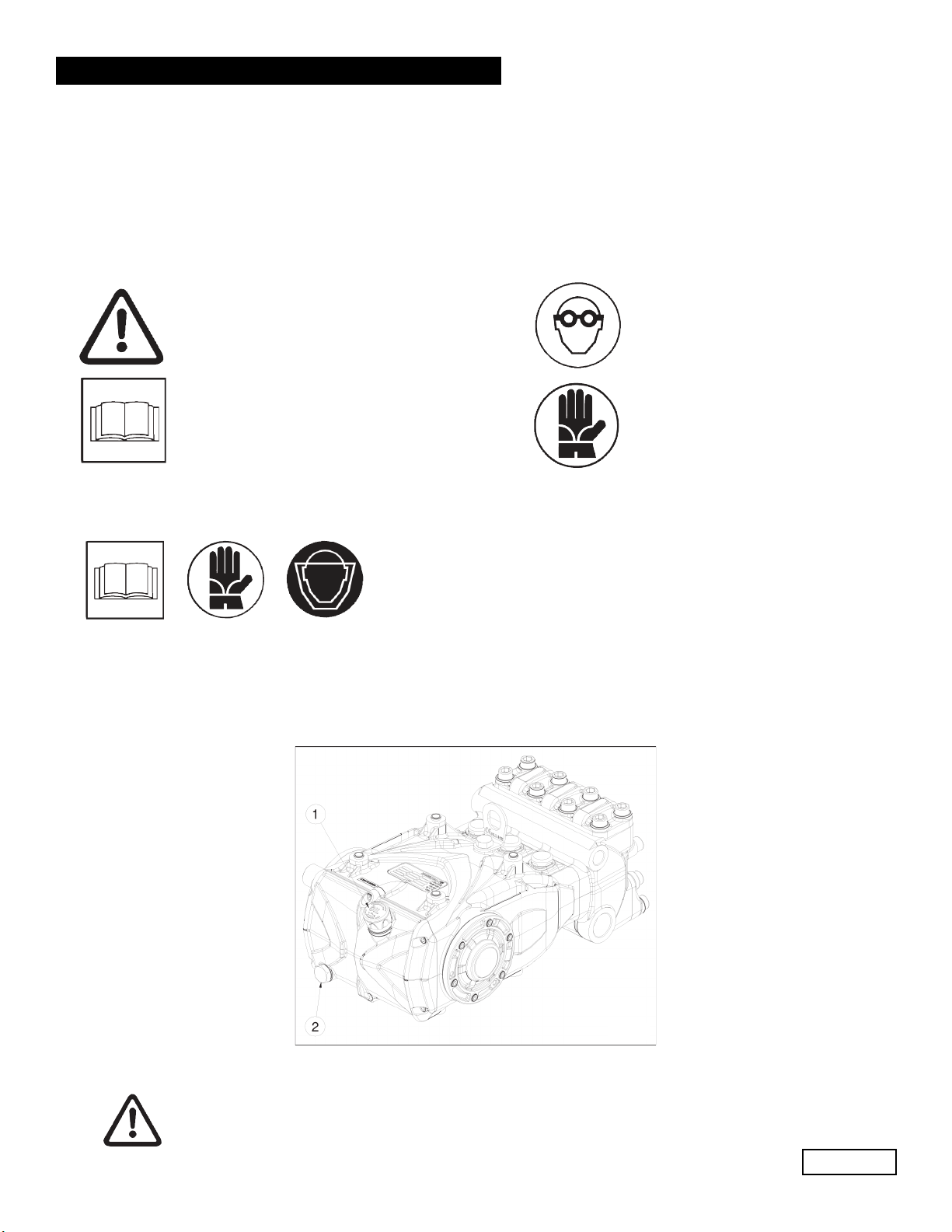
1.1 DESCRIPTION OF SYMBOLS
2. REPAIR INSTRUCTIONS
2.1 Repairing Mechanical Parts
Mechanical parts repair must be performed after removal of oil from the casing. To drain
the oil, remove the oil dipstick, (1, fig. 1) and then the draining plug (2, fig. 1)
GENERAL PUMP A member of the Interpump Group
Page 3
EV SERIES
Warning
Potential Danger
Danger
Wear goggles
Danger
Wear protective gloves
Read carefully and understand
the manual before operating
the pump
The oil must be placed in a suitable container and disposed of in special centers.
It absolutely must not be discarded into the environment.
Fig. 1
Ref 301038 Rev. A
07-20

2.1.1 Disassembly of the mechanical part. The operations described must be performed after
removing the hydraulic part, ceramic plungers and splash guards from the pump (par. 2.2.3, 2.2.4).
Remove in the following order:
- The pump shaft tab
- The rear cover
- The con-rod cap as follows: unscrew the cap fixing screws, remove the con-rod caps (Fig. 2) paying
attention to the sequence during disassembly.
- The side covers using for extraction 3 fully threaded M6x50 screws, inserting them in the threaded
holes as indicated in Fig. 3.
GENERAL PUMP A member of the Interpump Group
Page 4
EV SERIES
Fig. 2
Fig. 3
- Push the piston guides forward with their con-rods to facilitate side extraction of the pump shaft as
shown in Fig. 4
Fig. 4
Ref 301038 Rev. A
07-20

- Remove the pump shaft
- Complete disassembly of the connecting rods units by removing them from the pump casing and
removing the piston guide pins.
- Remove the pump shaft seal rings using common tools.
- Remove the piston guide seal rings as described below: Use the extractor code 26019400
(Fig. 5, pos. 1) and the pliers code 25027000 (Fig. 5, pos 2). Insert the gripper as far as possible onto
the seal ring with the aid of a hammer (Fig. 5/a), subsequently screwing the extractor to the gripper,
and use the extractor hammer (Fig. 6) until the ring to be replaced is removed (Fig. 7).
GENERAL PUMP A member of the Interpump Group
Page 5
EV SERIES
Fig. 5
Fig. 5/a
Fig. 6 Fig. 7
Ref 301038 Rev. A
07-20

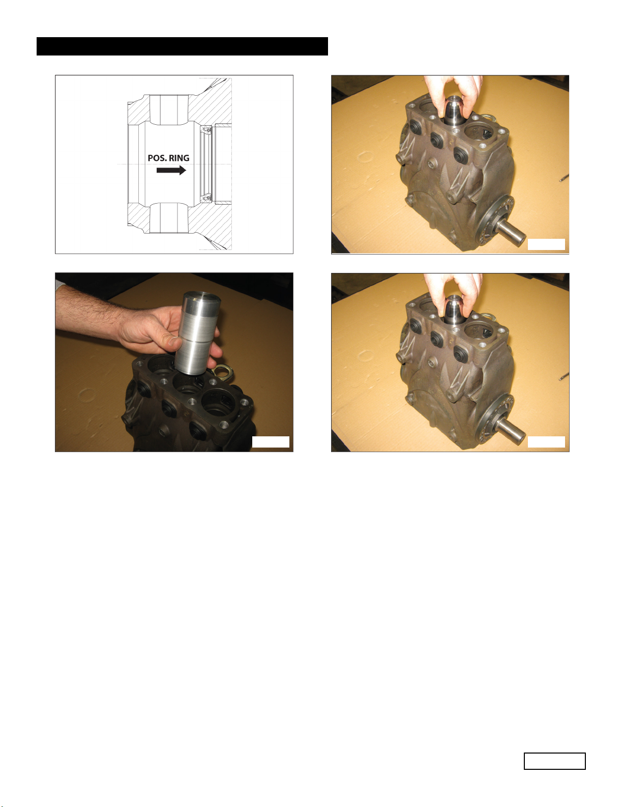
If the crankshaft shows diametrical wear in the area of contact with the lip seal, in order
to prevent the grinding operation, it is possible to reposition the ring in abutment with
the cover as shown in Fig. 8.
GENERAL PUMP A member of the Interpump Group
Page 6
EV SERIES
2.1.2 Assembly of mechanical parts
After having checked that the casing is clean, proceed with assembly of the mechanical part as described
below:
- Insert the piston / con-rod guide units into the pump crankcase.
To facilitate pump shaft insertion (without the tab), it is essential to repeat the operation performed during dis-
assembly, pushing the piston/con-rod guide units as far down as possible (par. 2.1.1).
- Before assembling the side cover on the PTO side, check the conditions of the radial ring lip
seal and relative contact area on the shaft.
If replacement is necessary, position the new ring using a tool (code 27904500) as shown in Fig. 8.
Before assembling the side covers, make sure there are O-rings on both of them and shim rings on the indi-
cator side cover only.
To facilitate filling of the first section and relative fitting of the covers on the crankcase, it is recommended to
use 3 partially-threaded M6 x 40 screws, (Fig. 8/a) to then complete the operation with the screws supplied
(M6x16).
Fig. 8 Fig. 8/a
- Couple the con-rod caps to their shanks (Fig. 9, pos. 1).
Note the correct assembly direction of the caps.
Ref 301038 Rev. A
07-20

GENERAL PUMP A member of the Interpump Group
Page 7
EV SERIES
- Fasten the caps to their respective con-rod shanks by means of M8x35 screws (Fig. 10) lubricating
both the underhead and the threaded shank, proceeding in two different stages:
1. Manually turn the screws until they begin to tighten
2. Tightening torque: 4.5 ft lbs. (20 Nm)
Alternatively, ensure:
1. Pre-tightening torque: 2.25 ft lbs. (10 Nm)
2. Tightening torque: 4.5 ft bs. (20 Nm)
- Fasten the caps to their respective con-rod shanks by means of M8x35 screws (Fig. 10) lubricating
both the underhead and the threaded shank, proceeding in two different stages:
Fig. 9
Fig. 10
- After having completed tightening operations, check that the con-rod head has a side clearance in
both directions.
- Insert the new piston guide seal rings as far as possible into the relative seat on the pump casing
(Fig. 11), following the procedure described:
use tools code 25027100 and code 27936600 composed of a tapered bush and a buffer. Screw the
tapered bush into the hole in the piston guide (Fig. 11/a), insert the new seal ring on the buffer as far
as it will go (determined by the height of the buffer) into its seat on the pump casing (Fig. 11/b),
remove the tapered bush (Fig. 11/c).
Ref 301038 Rev. A
07-20
Page 8
GENERAL PUMP A member of the Interpump Group EV SERIES
Fig. 11 Fig. 11/a
Fig. 11/b Fig. 11/c
- Mount the rear cover complete with the O-ring, positioning the dipstick hole upward.
- Insert oil in the casing as indicated in the Owner’s Manual
2.1.3 Disassembly / Assembly of bearings and shims
The type of bearings (taper roller) ensures the absence of axial clearance on the bend shaft. The shims are
defined to meet this necessity. For disassembly / reassembly and for any replacements, carefully observe the
following directions:
A) Disassembly / Reassembly of the bend shaft without replacement of the bearings
After having removed the side covers as indicated in par. 2.1.1, check the conditions of the rollers and their
relative tracks. If all parts are in good condition, clean the components carefully with a degreaser and redis-
tribute lubricant oil uniformly.
The previous shims can be reused, taking care to insert them only under the indicator side cover.
Once the complete unit is mounted (Indicator side flange + shaft + motor side flange), check that the rotation
torque of the shaft - with the con-rod disconnected - is a between 0.9 ft lbs. (4 Nm) and 1.35 ft lbs. (6 Nm).
To transition the two side covers closer to the crankcase, it is possible to use 3 M6x40 screws for the first
positioning phase, as already indicated above Fig. 8/a, and the screws provided for final fastening.
Shaft rotation torque (with the con-rod connected) should not exceed 1.8 ft lbs. (8 Nm).
Ref 301038 Rev. A
07-20
Page 9
GENERAL PUMP A member of the Interpump Group EV SERIES
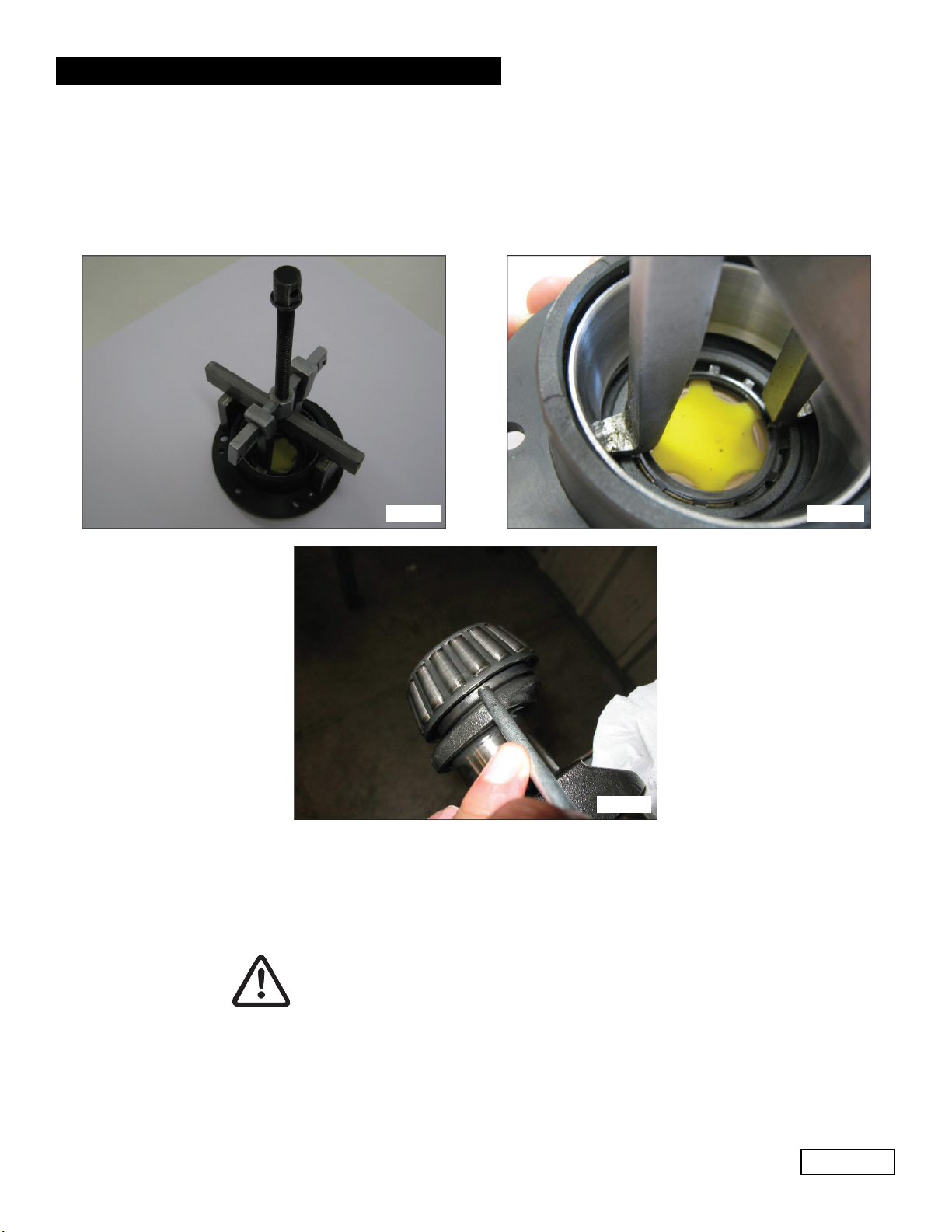
B) Disassembly / Reassembly of the bend shaft with replacement of the bearings
After removing the side covers, as described above, remove the outer ring nut on the bearings from its seat
on the covers, using an appropriate extractor as shown in (Fig. 12 and Fig. 12/a).
Remove the inner ring nut on the bearings from the two ends of the shaft, again using an appropriate
extractor or, alternatively, a simple “pin punch” as shown in Fig. 13
Fig. 12 Fig. 12/a
Fig. 13
The new bearings can be mounted cold with a press or rocker, supporting it on the lateral surface of the ring
nuts involved in press fitting with the rings. The fitting operation could be facilitated by
heating the parts involved at a temperature between 250° - 300 °F (120° - 150 °C), making sure that the ring
nuts are fully fitted in their respective seats.
Never exchange the parts of the two bearings.
Ref 301038 Rev. A
07-20
Page 10
GENERAL PUMP A member of the Interpump Group EV SERIES
Determining the shim pack:
Perform the operation while the piston/con-rod guide units are assembled, the con-rod caps are disconnected
and the con-rods are pushed downwards. Insert the pump shaft without tab into the casing, making sure the
PTO shaft comes out of the correct side.
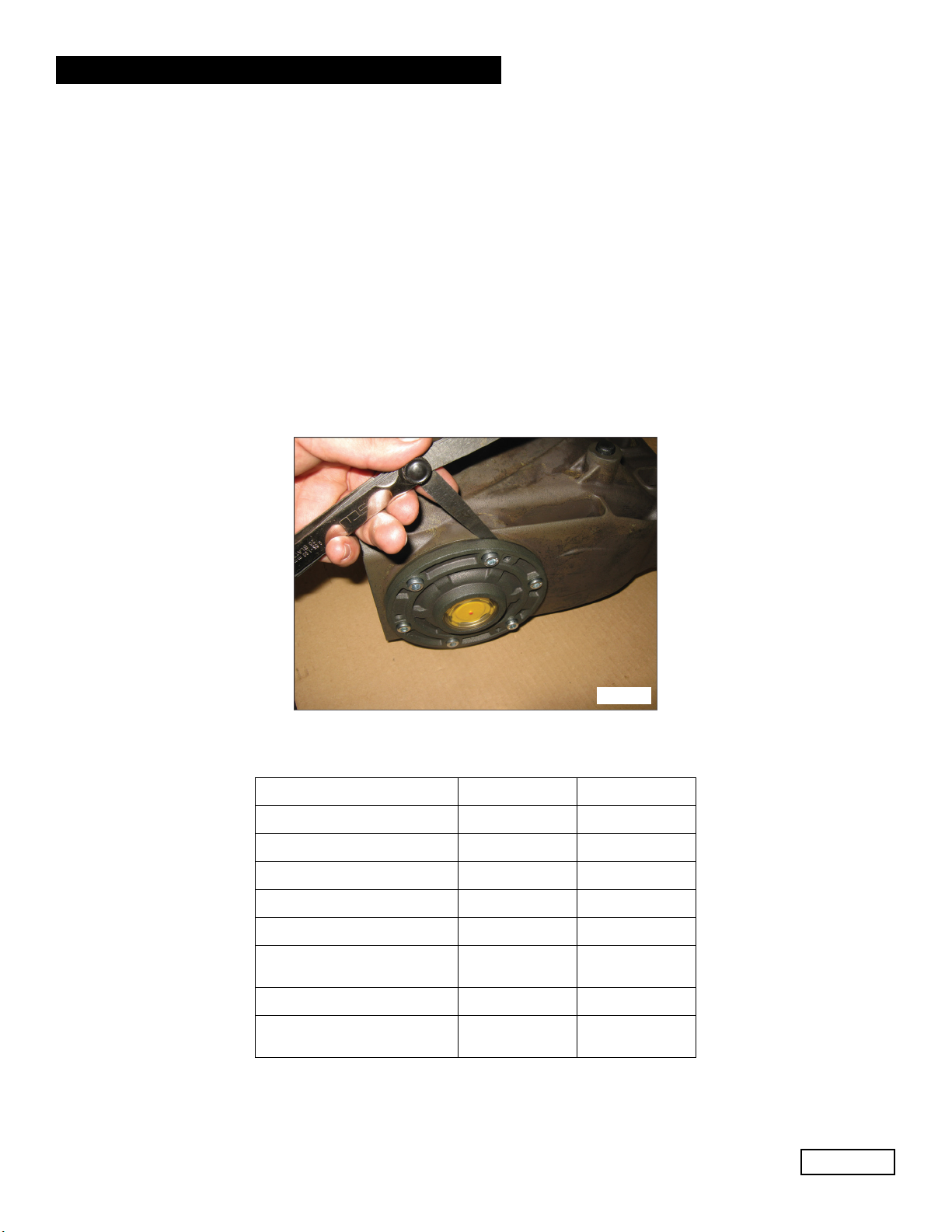
Secure the PTO side flange to the casing, taking care with the lip seal as described previously and tighten
the fixing screws to the recommended torque.
Then feed the flange on the indicator side without shims in the crankcase and start to move it closer, manual-
ly screwing the M6x40 service screws in equally, with small rotations such as to move the cover in slowly and
correctly.
At the same time, check that the shaft rotates freely by turning it manually.
Continuing the procedure in this way, a sudden increase in hardness during shaft rotation will soon be experi-
enced.
At this point, halt the forward movement of the cover and loosen the fixing screws completely.
With the aid of a feeler gauge, measure the clearance between the side cover and pump casing (Fig. 14).
Fig. 14
Proceed to determine the shim pack, using the table below:
Detected Measurement Shim type No. of Pieces
From: 0.05 - 0.10 / /
From: 0.11 - 0.20 0.1 1
From: 0.21 - 0.30 0.1 2
From: 0.31 - 0.35 0.25 1
From: 0.36 - 0.45 0.35 1
From: 0.46 - 0.55 0.35
0.10
1
1
From: 0.56 - 0.60 0.25 2
From: 0.61 - 0.70 0.35
0.25
1
1
Ref 301038 Rev. A
07-20
This manual suits for next models
5
Table of contents
Other Interpump Water Pump manuals


Popular Water Pump manuals by other brands


Sykes AmeriPumps
Sykes AmeriPumps GP100M Operation and maintenance instructions

DUROMAX
DUROMAX XP WX Series user manual

BRINKMANN PUMPS
BRINKMANN PUMPS SBF550 operating instructions

Franklin Electric
Franklin Electric IPS Installation & operation manual

Xylem
Xylem e-1532 Series instruction manual

Milton Roy
Milton Roy PRIMEROYAL instruction manual