Interscan Corporation GasD 8000 Series User manual

120-00012
GasD 8000 Series User Manual 12/14/2020
I
Interscan Corporation.
Instruction Manual
GasD 8000 Series Portable Gas Analyzer
P.N. 120-00012

120-00012
GasD 8000 Series User Manual 12/14/2020
II
Table of Contents
Section 1 - Introduction.................................................................1
1.1 Precautions ...............................................................1
1.2 Instrument Packing Contents....................................2
Section 2 –Instrument Description ...............................................3
2.1 Controls & Features...................................................3
2.3 Sample Probe...........................................................5
2.4 Analog Output Connections......................................6
2.5 Alarm Output Connection .........................................7
Section 3 –Instrument Operation..................................................8
3.1 Powering the analyzer...............................................8
3.2 Main Menu Navigation...............................................8
3.3 Measure Mode ..........................................................9
3.4 Setup Menu..............................................................11
3.5 Alarm Setup..............................................................12
3.6 Alarm Indications......................................................13
3.7 Charging The Batteries............................................14
Section 4 –Sampling..................................................................16
4.1 Zeroing The analyzer...............................................16
4.2 Taking Samples........................................................16
4.3 Sample Interferences ..............................................17
4.4 Auto Blockage Detection ..........................................17
Section 5 –Data Storage And Access ........................................18
5.1 FILES Menu .............................................................18
5.2 Accessing And Saving Data .....................................19
Section 6 - Calibration.................................................................21
6.1 Gas Calibration.........................................................21
6.2 Gas Calibration Procedure .......................................22
6.3 Digital Calibration .....................................................24
6.4 Digital Calibration Procedure....................................24
Section 7 –Sensor Replacement Procedure...............................26
7.1 Sensor Removal......................................................26
7.2 Sensor Installation....................................................28
Section 8 - Troubleshooting........................................................30
Section 9 - Warranty...................................................................31
Section 10 - Customer Service....................................................32
10.1 Return Authorization..............................................32
10.2 Spare Parts ...........................................................32

120-00012
GasD 8000 Series User Manual 12/14/2020
1
Section 1 - Introduction
Congratulations on your purchase of the INTERSCAN GasD8000 series portable gas
analyzer. The GasD8000 series analyzer represents a new chapter in Interscan’s
longstanding reputation of reliability and accuracy in portable gas monitoring.
Your instrument combines field-proven electrochemical sensing technology with an all-
new electronics package, intuitive controls, and a real-time graphics display. Key features
include:
•Real time continuous sampling and monitoring.
•Automatic data logging downloadable in a .csv (comma-separated values) file.
•SD Card data storage.
•User adjustable flow rate with auto blockage detection.
•User adjustable Alarm set point with audible and display indications as well as
voltage output at rear panel terminals.
•Voltage and current loop analog outputs available at rear panel terminals.
•Rechargeable Li-ion battery providing 5-8 hours of monitoring in the field.
•Instantaneous and accumulated measurement display (Monitor and Graph views).
•Quick connect sampling ports.
•Mini USB charging port.
1.1 PRECAUTIONS
Read this manual fully and carefully before using your instrument. This manual should
be read by anyone who will be operatingthe GasD8000 series portable analyzer to
ensure accurate measurement and long life.
NOTE 1:It is not necessary to calibrate the analyzer when received from the Interscan
or an authorized distributor. All Interscan analyzers arecalibrated at the factory priorto
shipment.
NOTE 2:It is a good idea to charge the batteries in your instrument before initial
operation. Connect the battery charger and run the instrument for 24 hours in OFF

120-00012
GasD 8000 Series User Manual 12/14/2020
2
MODE to allow the batteries to fully charge and the sensor to fully stabilize. See
section 3 for details on battery charging and navigating operation modes.
NOTE 3: It is recommended that the GasD8000 series portable analyzer be
connected to the power supply/battery charger during long term storage. See
section 3.2 for battery charging information.
WARNING: Some gas interferences can adversely affect instrument readings
and potentially damage the gas sensor. Be sure to read section 4.3 on Sample
Interferences carefully before taking any gas samples.
Carefully remove the analyzer from its packing container along with the accessories.
Inspect the instrument for any damage. Check that all accessories are included
according to the contents list shown below:
GasD8000 Series Portable Analyzer
Mini USB Wall Charger/Charging Cable
Sample probe assembly
User Manual
Contact the Interscan Service Dept. immediately (see section 11) to report any
damaged or missing items.
Any items reported damaged or missing after 30 days from delivery will not be
covered by INTERSCAN and the customer will be responsible for any
replacement or repair expense.
1.2 INSTRUMENT PACKING CONTENTS

120-00012
GasD 8000 Series User Manual 12/14/2020
3
Section 2 – Instrument Description
Figure 1 below shows the GasD8000 series portable analyzer case and front panel
features which are described in the table and sections that follow.
LCD DISPLAY –Displays all relevant
numeric and text information related to
sampling and menu navigation. Gas
values can be displayed numerically or
graphically. See section 2.1.1 for display
details.
IN FITTING –Quick connect socket for
introduction of sample via sample inlet
tubing. See section 2.2 for connection
details.
OUT FITTING –Exhaust port for sample
stream. No connection is necessary. DO
NOT BLOCK THIS PORT!
MINI USB PORT –USB connector for
battery charging and powered operation.
See section 3.5
TILT-BACK FEET –Provides a slight tilt
angle for table-top use. Feet are shipped
in the collapsed or “flat use” position but
can be engaged by simply rotating them
forward until they lock in place.
SD CARD –Slot for data storage memory
card. See section 6 for details on data
storage and accessing data.
CONTROL KEYPAD –Button cluster for
unit operation. See section 2.1.2 for
control details.
2.1 CONTROLS & FEATURES
CARRY HANDLE
TILT BACK FEET
INLET FITTING
LCD DISPLAY
SD CARD
MINI USB PORT
CONTROL
KEYPAD
FIGURE 1
OUTLET FITTING

120-00012
GasD 8000 Series User Manual 12/14/2020
4
CARRY HANDLE –Enables easy carrying of the instrument between sampling
locations. The handle can also be rotated 180° to the underside of instrument case
for deeper angled tilt during table-top use as shown in Figure 2. To rotate handle, pull
out on the handle mount on the left side of case and rotate handle towards the front
of the instrument. It will lock into place when at the 180° position. Be sure to collapse
the tilt back feet before rotating the handle.
FIGURE 2
2.1.1 DISPLAY FIELDS AND INDICATORS
The GasD8000series portableanalyzer displayscreenoffersavariety ofinformation
as detailed in Figure 3 below. Elements will be visible depending on the active mode
and operation being performed.
HANDLE MOUNT
MODE STATUS
INDICATOR
OPERATION
TIMER
BATTERY LIFE
REMAINING
READING VALUE
GAS & UNIT
LABELS
FLOW
RATE
ZERO MODE
INDICATOR
FIGURE 3
DATA SAVE
MODE ACTIVE
INDICATOR
ALARM
INDICATOR

120-00012
GasD 8000 Series User Manual 12/14/2020
5
2.1.2 CONTROL KEYPAD
The analyzer’s control keypad is detailed inFigure 4 below. Each button isdescribed
in the table that follows.
POWER BUTTON –Press to turn power
to instrument ON. Press from the MAIN
MENU to turn power OFF.
ARROW BUTTONS –Used to navigate
through the instrument’s menus and enter
values during numeric and text entry.
Proper use is indicated in specific function
descriptions.
ENTER BUTTON –Used to advance
through the sequential menus and finalize
certain functions.
STOP BUTTON –Used to back up in
sequential menus or end a particular
function.
SAVE BUTTON –Press at any point
during sampling to save current data to
memory card.
2.3 SAMPLE PROBE
Inmostcases,gassamplewillbecollectedviaaprovidedSAMPLEPROBEwhichconsists
of probe handle and tip, a 3 foot length of PTFE (Teflon) or polypropylene tubing and a
quick disconnect tube adapater for connection to the INLET of the instrument. This
assembly is shown below.
POWER BUTTON
ARROW BUTTONS
ENTER BUTTON
STOP BUTTON
SAVE BUTTON
FIGURE 4

120-00012
GasD 8000 Series User Manual 12/14/2020
6
To connect the probe to the instrument INLET first push down on the metal locking tab of
the inlet fitting then plug the tube adapter into the “IN” connector until you hear the locking
mechanism click into place (below, left). To remove the tube adapter, press down on the
metal locking tab onthe top of the connector while pulling out on the tubing (below, right).
2.4 ANALOG OUTPUT CONNECTIONS
The GasD8000 Series analyzer is equipped with 0-100 mV** and a 4-20 mA analog
output signalsavailableatthe10pinrearpanelterminal blockasshown inthetablebelow.
For mV output, connect between terminals 1 or 2 (GND) as the negative reference and
terminal 7 (AOUT2) as the positive output as shown in blue in the table below. For 4-20
mA output, use terminal 3 (VCC) as the output and terminal 8 (AOUT1) as the return,
shown in green in the table below.
PROBE
TIP
PROBE
HANDLE
TUBING
TUBE
ADAPTER

120-00012
GasD 8000 Series User Manual 12/14/2020
7
Connect to the terminal block by inserting wire conductor into the desired terminal and
tightening the terminal’s screw. The terminal block can be removed from the rear panel for
ease of wiring by gently pulling the block away from the panel. Re-connect the block by
gently pressing it back into thereceptacle.
PIN
NAME
TYPE
DESCRIPTION
1
2
3
4
5
6
7
8
9
10
GND
GND
VCC
-
-
ALM
AOUT2
AOUT1
-
-
Reference
Reference
Reference
N/C
N/C
Alarm Signal
Analog Voltage Output
Analog Current Output
N/C
N/C
Local Device Ground
Local Device Ground
+5 Volts
-
-
+5V on alarm actuation
0-100 mV corresponding to gas range
4-20 mA corresponding to gas range
-
-
**NOTE –the mV analog output can be adjusted up to 2500 mV at full scale. Contact the
INTERSCAN SERVICEDEPT if you wish to modify the voltage output.
The GasD8000 Seriesanalyzer is equipped withan alarm output signal thatwill activate
when gas concentration level exceeds the user set Alarm set point level (see section 3.7).
This is a 5V signal available at terminal 6 (Alarm Signal) referenced to terminals 1 or 2
(GND).
2.5 ALARM OUTPUT CONNECTION

120-00012
GasD 8000 Series User Manual 12/14/2020
8
Section 3 – Instrument Operation
To turn the instrument on, press the green
power button. The MAIN MENU screen showed
on the right will be displayed.
Check the battery life indicator in the lower right
corner of the display and confirm that adequate
battery liferemains for use. Expected battery life
is 5-8 hours on a full charge depending on
nature of use. See section 3.2 for details on charging the batteries.
To power the unit down, navigate to the MAIN
MENU screen shown on the right and press the
green power button. The screen will prompt you
to confirm power down as shown. Press the
RIGHT ARROW button to confirm power down.
NOTE: Normal power down only works from the MAIN MENU screen. Access the main
menu screen from any of the operating modes or sub-menus by successively pressing
the STOP button until the MAIN MENU is displayed.
To navigate through the MAIN MENU, use the UP or DOWN ARROW buttons to highlight
the desired menu selection then use the RIGHT ARROW button to open the highlighted
sub-menu. This is the procedure for navigating any sub-menu in GasD8000 series
portable analyzer.
3.1 POWERING THE ANALYZER
3.2MAIN MENU NAVIGATION

120-00012
GasD 8000 Series User Manual 12/14/2020
9
The MAIN MENU offers 3 sub-menu selections that are detailed below:
MEASURE –Sequential sub-menu of primary operating modes as follows:
- STARUP MODE > OFF MODE > ON MODE.
See section 3.3 for details on the MEASURE sub-menu.
SETUP –Sub-menu of user adjustable parameters and functions including:
- FLOW RATE
- SAMPLING MODE
- DATE/TIME
- ALARM
- GAS CALIBRATION
- DIGITAL CALIBRATION
- FACTORY SETTINGS
See section 3.6 for details on the SETUP sub-menu.
FILES –Sub-menu of data storage parameters as follows:
- Create (create and name new data file)
- Delete (delete any existing data file)
- Select (select any existing data file for next sample storage)
See section 6 for details on the FILES menu and accessing data.
MEASUREMODEistheprimaryoperatingmodeforGasD8000seriesportableanalyzer.
It is comprised of a sequence of 3 separate modes as detailed below.
3.3MEASURE MODE

120-00012
GasD 8000 Series User Manual 12/14/2020
10
SENSOR STABILIZING MODE
Upon selecting MEASURE from the main
menu, the unit will automatically advance to
SENSOR STABILIZING mode. A 5-minute
timer will count down while the sensor is
allowed to stabilize following power up. The
screen shown to the right will be displayed
duringSENSORSTABILIZINGmode.When
the startup timer elapses, the instrument will automatically enter OFF MODE. To
bypass the stabilization period and manually advance to OFF MODE, press the
ENTER button.
OFF MODE
In OFF MODE, the pump is turned off and the
screen showed on the right will be displayed.
The timer at the bottom of the display indicates
how long the unit has been in an operational
mode.
This is the mode the instrument should be kept
in when poweredbutnotinuse.To advancetoONMODEfromOFFMODE,pressthe
ENTER button. To return to the main menu from OFF MODE, press the STOP button.
ON MODE
ONMODEistheprimarysamplingmodeforthe
analyzer. In this mode, the pump is turned on
and the screen shown on the right will be
displayed. The display will indicate the gas
concentrationwhiletheactivetimercontinuesto
display sample duration. Zeroing of the display
can be accomplished from this mode as well
(See section 5.1 for more on zeroing).

120-00012
GasD 8000 Series User Manual 12/14/2020
11
GRAPH DISPLAY
A graphical display of the continuous reading is
also accessible in ON MODE by pressing the
RIGHT ARROW button. The current numeric
reading value is displayed in the lower right
corner.
Advance forward through the mode sequence by pressing the ENTER button as
needed.Advancebackwardthroughthemode sequencebypressingtheSTOP button
as needed. Pressing theSTOP button successivelywillreturn the display to the MAIN
MENU where the SETUP and FILE menus can be accessed.
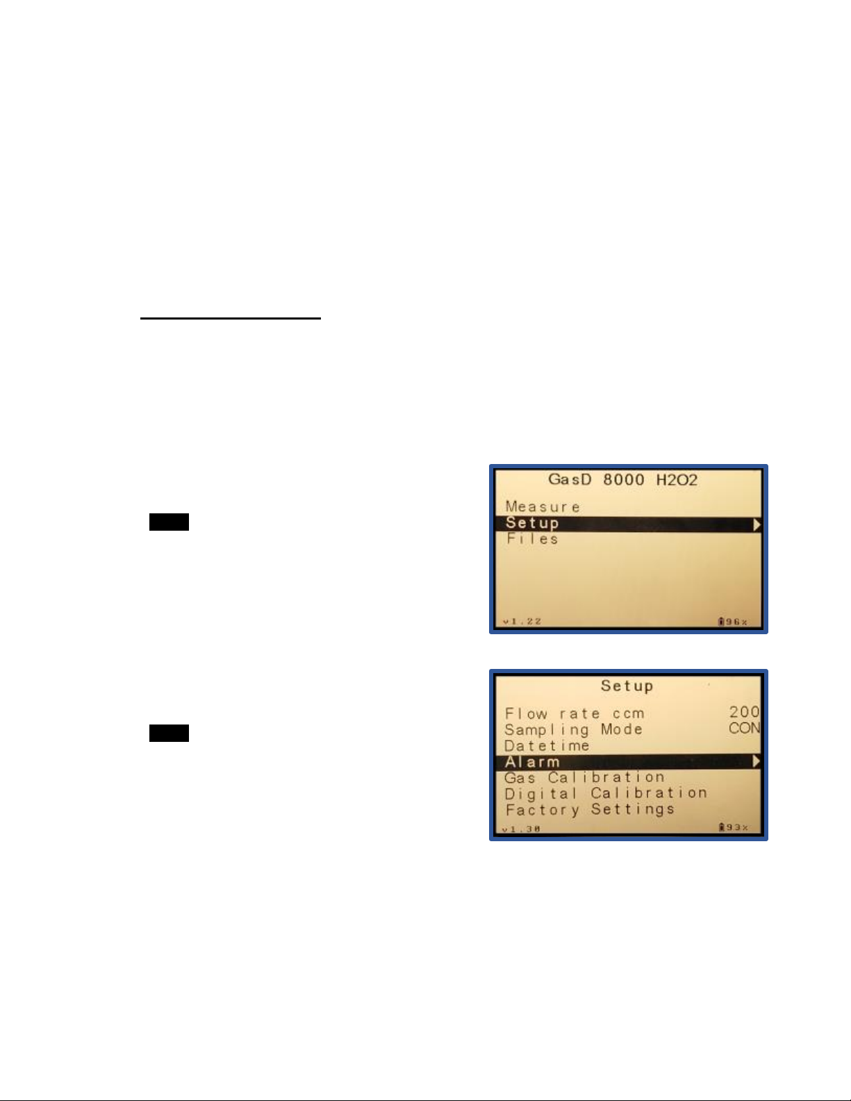
The Setup Menu shown on the right offers access to
user adjustable parameters and maintenance
functions. This menu is detailed below.
Flow rate –cc / min –Nominal setting = 200 cc / min unless stated otherwise. Do
not change this setting.
Sampling Mode –Nominal setting = CON. This setting controls the SAMPLE
MODE procedure with 4 options as follows:
•Continuous - Sample is drawn continuously. This is the correct mode for
use in the GasD8000 Series analyzer
•HAL1 –N/A for 8000 Series analyzers
•HAL2 - N/A for 8000 Series analyzers
•HAL3 - N/A for 8000 Series analyzers
Datetime –Set the date and time according to the user’s time zone.
Alarm –Allows enabling of Alarm functionalityand setting of Alarm set point above
which Alarm indications will activate. (See section 3.7).
3.4SETUP MENU
120-00012
GasD 8000 Series User Manual 12/14/2020
12
Gas Calibration –Allows for calibration using a calibration gas standard. See
sections 7.1 & 7.2).
Digital Calibration –Allows for calibration without calibration gas via Interscan’s
Sensor Express Program. (See sections 7.3 & 7.4)
Factory Setup –A password protected setup sub-menu for factory setup only.
The GasD8000 Series portable analyzer is equipped with an alarm feature that provides
visual and audible indication when the gas concentration level exceeds a user set alarm
level. This section details alarm setup and functionality.
To access the Alarm settings menu, highlight
“Setup” on the main menu then press the
RIGHT ARROW button to select this sub-menu
as shown to the right.
Use the DOWN ARROW button to highlight
“Alarm” and press the RIGHT ARROW button to
select as shown to the right.
3.5ALARM SETUP

120-00012
GasD 8000 Series User Manual 12/14/2020
13
The “GAS HIGH” value is the alarm set point
value above which alarm indication will occur.
Highlight this parameter then use the RIGHT
ARROW button to highlight the numeric
field(s) you wish to change. Use the UP or
DOWN ARROW buttons to change the
numeric value of the desired fields. Once
satisfied with the value, use the LEFT
ARROW button to exit the parameter value field.
NOTE: Decimal places displayed in the Alarm numeric value field will mirror the decimal
place count of the primary gas range.
Use the DOWN ARROW button to highlight
the “ENABLE” parameter, then the RIGHT
ARROW button to highlight the value. Using
the UP/DOWN ARROW buttons, select
“YES” to enable the alarm function or “NO”
to disable it.
Press the LEFT ARROW button to exit the Alarm menu and press again to exit the Setup
menu and return to the Main Menu.
3.6ALARM INDICATIONS
When enabled, the alarm feature will activate any time the displayed gas concentration
level exceeds the user set alarm level.

120-00012
GasD 8000 Series User Manual 12/14/2020
14
During an alarm condition, “ALARM
THRESHOLD!” will flash on the main display
as shown on the right and a steadily repeating
beeptonewillsoundindicatinganactivealarm
condition. When the concentration value falls
below the alarm set point, the alarm
indications will deactivate.
The GasD8000 series portable analyzer includes a wall charger that can be used to
recharge the instrument’s batteries, as well as power the instrument during extended use.
The expected battery capacity on a full charge is 5-8 hours depending on nature of
use.
When the battery charge drops below 10%, the display will indicate “Low Battery!” at the
bottom of the screen. Follow the procedure below to re-charge the batteries:
1. Select the desired plug type on the multi-region charger plug unit.
2. Plug the large USB connector end of the supplied charger cable into one of the
charger’s USB ports.
3. Connect the mini-USB connector into the mini USB port on the front panel of the
instrument.
4. Plug the charger into the wall.
5. Charge until the battery life indicator on the instrument display reads “100%”.
If charged with the power off, the GasD8000
series portable analyzer will automatically power
up to the MAIN MENU as soon as the charger is
connected to the USB port. If the instrument is
then powered down the display will show a
charging percentage indicator as shown on the
right. The instrument can be charged with power
on or off.
3.7 CHARGING THE BATTERIES

120-00012
GasD 8000 Series User Manual 12/14/2020
15
NOTE: For fastest charging, do not connect any other USB devices to the charger.
NOTE: The internal batteries must have a charge to maintain the sensor bias voltage
and minimize sensor warmup time. It is recommended you keep the instrument
connected to the power supply for long term storage or extended use.

120-00012
GasD 8000 Series User Manual 12/14/2020
16
Section 4 – Sampling
4.1 ZEROING THE ANALYZER
It is always a good idea to zero the analyzer prior to sampling. To accomplish this, ensure
the unit is inON MODE and hasbeenallowed tostabilize in thismodefor several minutes.
Confirm that the flow rate has settled at the nominal flow rate (200 mL/m) and the display
valueisnotrisingorfallingsignificantly.Zerotheinstrumentinanareawherecleanambient
air is present as follows:
- Press the UP ARROW button. The ZERO
indicator will now be highlighted indicating
ZERO MODE is active.
- Press the ENTER button. “Set ZERO” will
be indicated under the main display for 3
seconds indicating the value is being
zeroed. The display value will gradually
decrease toward 0. If zero is not attained,
repeat the process by pressing ENTER
again.
- When finished, press the DOWN ARROW
button to exit ZERO MODE.
The instrument is now ready for sampling.
While in ON MODE, direct the SAMPLE PROBE toward the desired sample location and
allow sample to be drawn. The instrument will respond to any target gas in the area within
a few seconds.
Whenfinished with sampling, press the STOP BUTTON once from ON MODE to return to
OFF mode. This stops the automatic data storage saving data space and battery life.
4.2TAKING SAMPLES

120-00012
GasD 8000 Series User Manual 12/14/2020
17
4.3SAMPLE INTERFERENCES
Gases present in the environment other than the "target" gas of measurement,
referred to as “interfering gases”, may affect analyzer response. Interferences are not
necessarily linear and may also exhibit time dependent characteristics.
Gas interference charts detailing how interfering gases may affect specific target gas
readings are available on the Interscan Corp. website at the link below.
https://www.gasdetection.com/the-tech-center/instrument-sensor-
performance/interfering-gas-data/
The special case of how alcohols affect electrochemical sensors is discussed in this
Knowledge Base article.
https://www.gasdetection.com/gas-detection-knowledge-base/ethylene-oxide-eto-or-
eo-monitoring-applications/alcohol-and-electrochemical-sensors/
For further information on the effects of interfering gases, please contact the factory.
4.4 AUTO BLOCKAGE DETECTION
The GasD8000 series portable analyzer is
equipped with flow rate detection to protect against
unwanted blockages in the inlet line. In the event of a
sudden drop in flowrate in ON mode, the screen
shown to the right will be displayed. This indicates a
blockage of the inlet probe, filter or sample tube that
must be addressed before sampling can resume.
Should this message appear, check the probe, filter and sample tube for any blockages or
kinksthatmight restrictflow. Clear this blockage then press the ENTER buttonto proceed.

120-00012
GasD 8000 Series User Manual 12/14/2020
18
Section 5 – Data Storage And Access
Sample data can be stored on standard SD card media (a 32 GB card is provided with the
instrument). Data is saved to the SD card automatically in ON mode and SAMPLE mode
at a rate of one sample per second whenAUTO SAVE is enabled (this is the default status
on power up).
“SAVE” will be displayed in the lower left corner of the display in ON and SAMPLE modes
indicating that the AUTO SAVE feature is active. AUTO SAVE mode can be disabled by
pressing the SAVE button in any mode. When disabled, “SAVE” will NOT appear on the
display in ON and SAMPLE modes.
Leaving the instrument in AUTO SAVE mode is the surest way to ensure data storage is
completed. The trade-off is the potential for storing long strings of unnecessary data every
second in ON mode. For this reason the option is provided to disable AUTO SAVE when
the instrument is idle anddata storage is known to be unnecessary.
5.1 FILES MENU
Data is stored in user created files. The user must create a file for storage and then select
the desired file as the data location for future data collection. All file management is
executed from the FILES menu as detailed below.
File management is accessed from the MAIN
MENU by selecting FILES and then pressing the
RIGHT ARROW button to open the FILES sub-
menu shown on the right. Highlight the desired
option using the DOWN and UP ARROW buttons
and select the desired option using the RIGHT
ARROW button. FILES options are shown below.
This manual suits for next models
1
Table of contents
Other Interscan Corporation Measuring Instrument manuals

Interscan Corporation
Interscan Corporation 4000 Series User manual

Interscan Corporation
Interscan Corporation 4000 Series User manual

Interscan Corporation
Interscan Corporation 4000 Series User manual

Interscan Corporation
Interscan Corporation GF1900 User manual

Interscan Corporation
Interscan Corporation GF1900 User manual
Popular Measuring Instrument manuals by other brands


ELOKON
ELOKON ELOSHIELD instruction manual

Honeywell
Honeywell EW600 Series Operating and installation instructions

SYSTRONIK
SYSTRONIK BLUELYZER ST instruction manual

Extech Instruments
Extech Instruments EN510 user manual

Winter
Winter 5 StV Installation and maintenance instructions

Stabila
Stabila LAX 50 G operating instructions


