GQ Electronics GMC-500 User manual

GQ GMC-500/GMC-500+
Geiger Counter
User Guide
GQ Electronics LLC
Revision 1.2
Sep-2017

2
Document Revision History:
Re.1.20 ,Sep-2017
Re.1.01 ,Apr-2017
Re.1.00 ,Feb-2017

3
Table of Contents
User Guide...........................................................................................................................1
Table of Contents..................................................................................................................3
Overview...................................................................................................................................5
Specifications:..................................................................................................................5
Packing List:.....................................................................................................................6
How it works?............................................................................................................................6
Caution.......................................................................................................................................6
Background Safe Levels ............................................................................................................6
Hardware setup...............................................................................................................7
Software set up................................................................................................................7
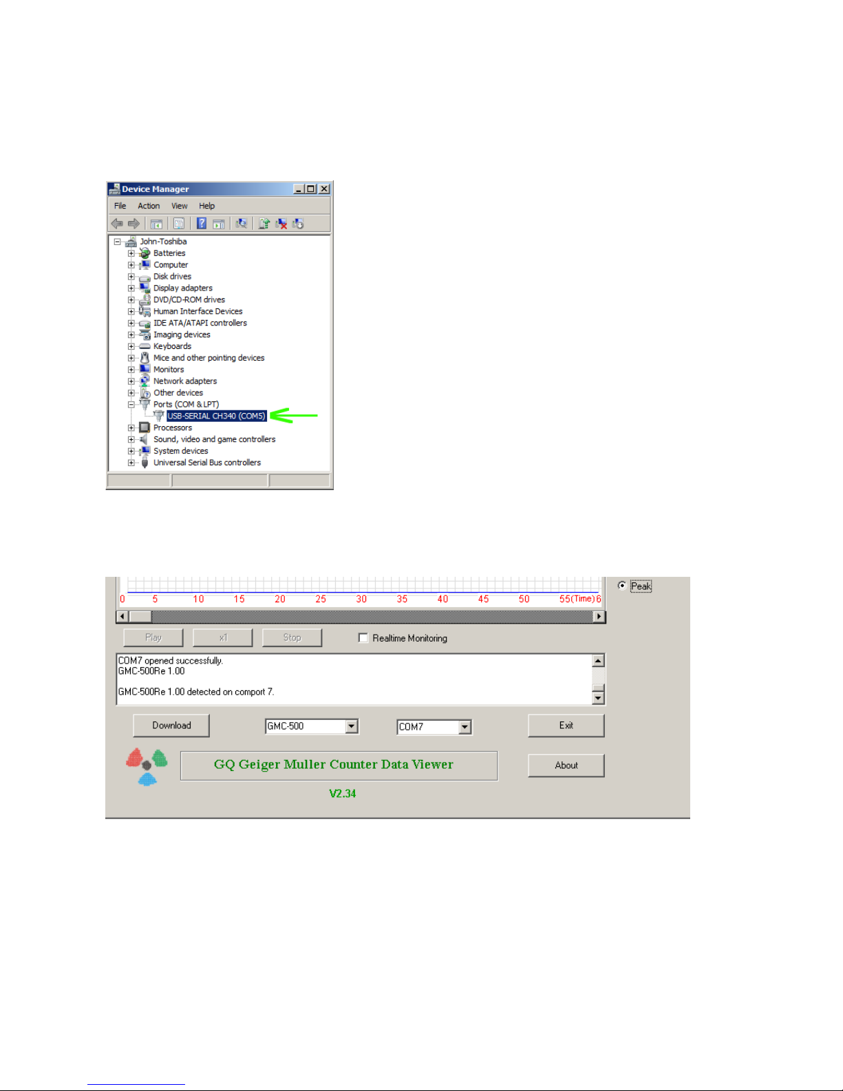
Verify USB driver installation in Windows...........................................................................8
S1 key...............................................................................................................................9
S2 key...............................................................................................................................9
S3 key...............................................................................................................................9
S4 key..............................................................................................................................9
Power saving mode ........................................................................................................9
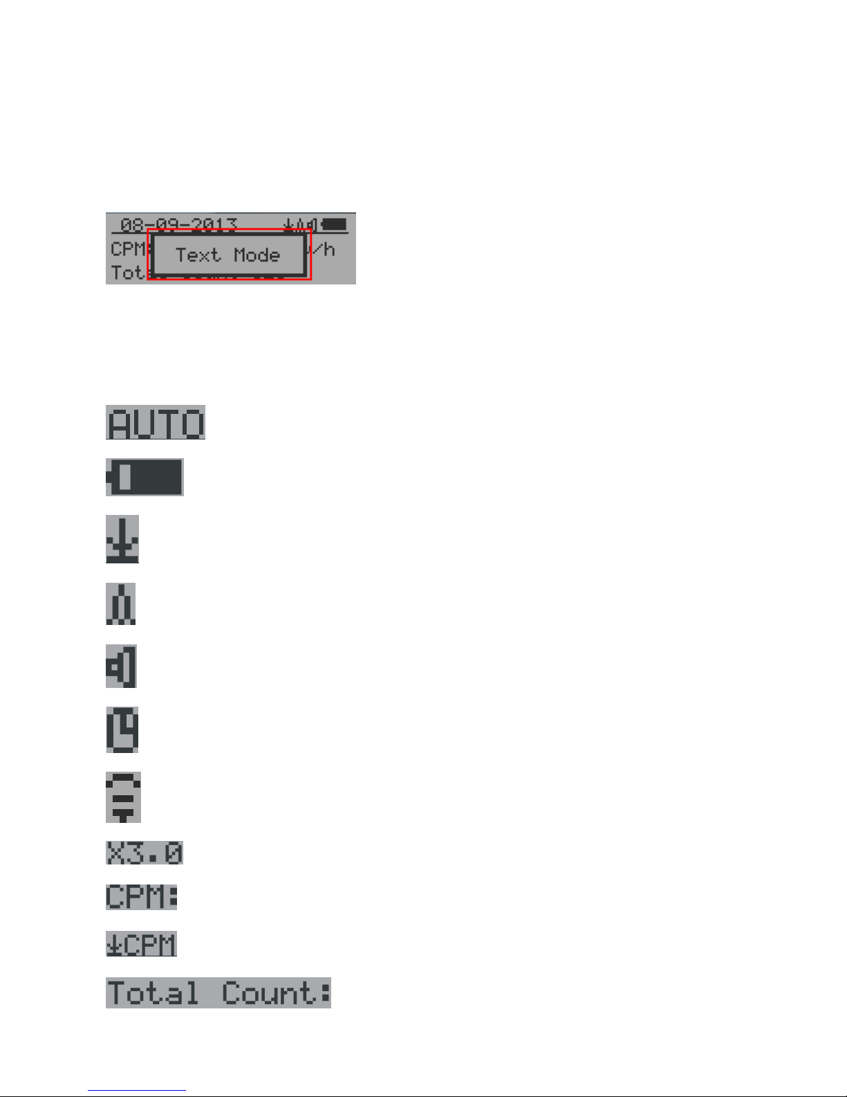
Popup Windows.............................................................................................................10
Graphic User Interface (GUI) ..............................................................................................10
Graphic Icons:................................................................................................................10
Dual Display Modes ................................................................................................................12
Display Modes .........................................................................................................................13
Graphic Mode:...............................................................................................................13
Text Mode:......................................................................................................................13
Large Font Mode:..........................................................................................................14
User Option....................................................................................................................15
Alarm Set........................................................................................................................15
Date and Time setting..................................................................................................16
Data Saving Setting......................................................................................................16
Threshold Data Saving Setting...................................................................................17
Add Note or Add Location for data saving ................................................................17
Note/Location Input.......................................................................................................18
Erase Saved History Data ...........................................................................................18
Display Option................................................................................................................18
Swivel Display Option....................................................................................................18
WiFi Setup and Check..................................................................................................19
WiFi IP address.............................................................................................................19
WiFi Mac address..........................................................................................................19
WiFi Signal Level Checking.........................................................................................19
Internet Data Server Setting........................................................................................20
Website server...............................................................................................................20
URL for Website server................................................................................................20
Website server User ID................................................................................................20
Website server Geiger Counter ID.............................................................................21
WiFi Data Logging Period............................................................................................21
WiFi Data Logging Testing ..........................................................................................21
Calibrate the reading ....................................................................................................22
Factory reset..................................................................................................................23
Battery Status ................................................................................................................23
Battery Type...................................................................................................................23
Power saving mode ......................................................................................................24
Motion Detection............................................................................................................24
Reset Total Count.........................................................................................................24
Gyroscope Data Display ..............................................................................................25
Communication Baud Rate..........................................................................................25

4
Reverse Display ............................................................................................................25
Contrast Adjustment.....................................................................................................25
Timed Count...................................................................................................................26
Set a schedule...............................................................................................................26
Set Timed Count Duration...........................................................................................26
Start a Timed Count......................................................................................................27
About...............................................................................................................................28
Model information..........................................................................................................28
Firmware version...........................................................................................................28
Unit serial number.........................................................................................................28
GQ GMC Data Viewer Software.........................................................................................29
Online Geiger Counter World Map .....................................................................................32
www.GMCmap.com................................................................................................................32
Software...................................................................................................................................32
Auto Submit Data Protocol......................................................................................................32
Applications....................................................................................................................33
Stationary Application...................................................................................................33
Other technical details you may want to know.................................................................34
Data Port.........................................................................................................................34
USB Port.........................................................................................................................34
Data collection time......................................................................................................34
Extend battery operating time.....................................................................................34
Third party software developers .................................................................................34

5
Overview
The.GQ GMC-500 digital Geiger Muller Counter is designed to be a portable and convenient device.
It can be used as industrial, commercial maintenance, research, evaluation, simulation and other
analytical or scientific applications in areas such as industrial plants, public utilities, universities,
laboratories, and electronic repair shops. The device comes with built in audible and visual signals
for the level of radiation detected. It can be used for radiation detection and monitoring both indoor
and outdoor, as well as in other similar environments. It features automatic data recording. It can
continually monitor the radiation and log the data each second into internal memory. When
connected to a PC, software can download the radiation history data to the computer and the user is
able to analyze those data later. The GQ GMC-500 installed a high contrast black/white LCD
module, one front LED indicator and one analog data port. The analog data port can be connected
to any third party device application as data input.
The GMC-500 installed a WiFi module, user is able to log the data via WiFi wirelessly.
The device is equipped with an USB port, utilized for communication and external power
supply/charging of the internal rechargeable Li-Ion 3.6V/3.7V battery.
The GQ GMC-500 internal rechargeable battery can be charged with the a standard USB port, USB
charger or with a computer USB port. Using the external power, continuous data monitoring is
possible. Using either power adapter you will not have to worry about the batteries charge condition
or any data loss.
The main board also has a real time clock on board for time related data logging purposes.
The GMC-500 installed multiple sensors to ensure full scale/range measurement and higher
accuracy. .
Specifications:
Range of dose rate indications, µSv/h 0.00 to ~4250
(0.00 to ~42500 on GMC-500+)
Range of exposure dose rate indications, mRem/h 0.00 to ~425
(0.00 to ~4250 on GMC-500+)
Range of registered beta radiation energy MeV 0.25 to 3.5
Range of gamma radiation energy, MeV 0.1 to 1.25
Range of registered X-ray radiation energy MeV 0.03 to 3.0
Reproducibility of indication 10%
Alarm levels by CPM 0 to 655350 (continuously)
0 to 982980 (GMC-500+)
Alarm levels by uSv/h 0.00 to 4250 (42500 on GMC-500+)
Alarm levels by mRm/h 0.00 to 425 (4250 on GMC-500+)
Date indication YYYY-MM-DD (continuously)
Time indication HH-MM-SS (continuously)
Elapsed time indication 99 years(maximum)
Timed Count 1 Second to 256 days(programmable)
Scheduled Timed Count 0 Second to 256 days(programmable)
Radiation detection , x
Detectable Radiation Range 0.1 ~ 3 MeV
Instrument Background < 0,2 pulses/s
Working Voltage 3.6-3.7V
Display LCD dot matrix, back lighted
On board Memory 1M Bytes flash memory for data storage
Power:Consumption 25mW –125mW (count rate dependant)
Power:Supply 3.7V Li-Ion battery / USB power
Dimensions 135 x 78 x 25 mm(5.25”x 3” x 1”)

6
Packing List:
1. GMC-500/GMC-500+ main unit.
2. USB cable
3. Quick start guide
4. Download link for SoftGeigerCounter software and USB driver for Windows 32 and 64 bits
(see Quick start guide)
5. Download link for a complete user guide in pdf version.
How it works?
The GQ-500/GMC-500+ Geiger Counter installed Geiger tubes to detect radiation.
When the radiation pass through the Geiger tube, it triggers electrical pulses for the CPU to register
as count. The basic count rate unit is CPM(Count Per Minute). The CPM count rate indicates the
radiation level and it can be converted to a other traditional radiation units, such as uSv/h or mR/h.
After unit turned on for one minute, it will show the background radiation reading. The background
radiation reading (in CPM) indicates the nature radiation detected at that minute. This reading may
change from time to time and location to location. To get accurate reading, user may need to get an
average value over a longer time period.
The GM-500 built-in intelligent algorithm always select one of the most adequate sensors to
measure the target, so that to guarantee the accuracy of the measurement.
Caution
1. Avoid doing measurements when battery low.
2. Do not get the Geiger counter wet. Use sealed plastic bag to void wet.
2. Avoid doing measurements in direct sunlight.
3. Avoid directly contact the radioactive material. Use sealed plastic bag if needed.
4. Turn off the unit when not in use.
5. Keep it in a protective pouch after use.
6. When the unit not in use, store it in a dry place or box. This will avoid mechanical part be
oxidized, such as button or battery contacting points.
-
Background Safe Levels
Suggested background readings levels:
1. Safe level. Less than 50CPM or 0.325uSv/h. Means no worry at all.
2. Attention level. 51CPM –99CPM. OR 0.326uSv/h –0.65uSv/h . Means you need to find out
why .
3. Warning level. More than 100CPM or more than 0.65uSv/h. Means do not stay in this area for
long period.

7
Hardware setup
There are four buttons on the front of the unit: S1, S2, S3 and S4 (from left to right)
1. Power up the unit. Pressing the S4 (power) key for 3 seconds will turn on the unit.
Check the battery level. Charge the battery fully when first time use.
It may take a few hours to get the battery fully charged. Check the battery icon on the display,
a fully charged battery icon will be filled with solid color, without flashing.
2. Set date/time. Press the S4 key to enter the menu and set the date and time. This is very
important for time stamping the recorded data. Do not skip this step. Most of the data are
related to the date and time.
3. Set the backlight timeout in second, in order to minimize the power consumption.
Set the power savings mode. If the power savings mode is ON, then the LCD display will be
turned off after 30 second if no key is being pressed during this period.
4. Now the unit is ready to use. You should see the background CPM rate in absence of a
radioactive source.
Note: There is a transparent protective sheet covering the units surface. Users need to remove it to
get better view of the LCD display.
Software set up
Before connecting the GMC-500/GMC-500+ Geiger Counter to a computer, download the
application software and install the USB driver. Download these from:
http://www.gqelectronicsllc.com.
1. The unit needs an USB driver in order to communicate with the application software.
Running GQGMCGeigerCounterUSBDriverV4.exe will install the USB driver.
2. GMCDataViewer.exe is for viewing the data on a computer.
3. SoftGeigerCounterGMC500.exe is a soft copy of GMC-500 demo software.
For technical questions and support, please use the forum at the following link:
http://www.GQElectronicsLLC.com/forum
For the latest software, please visit our software download page:
http://www.gqelectronicsllc.com/comersus/store/download.asp

8
Verify USB driver installation in Windows
Once the GMC-500/GMC-500+ is connected to a computer, from the device manger, you should
see which COM port is assigned to the unit . See the example below. Windows assigned COM3 to
the GMC-500 unit in this example.
For the data viewer or the data logger software, selecting COM5 will establish the connection to the
GMC-500 Geiger counter for the above example

9
GQ GMC Geiger Counter Multi-Function Keys
The multi-function keys S1,S2,S3 and S4 explained:
Vertical Display Mode Horizontal Display Mode
These key’s function will be reassigned dynamically based on the context of the current (sub-) menu
being displayed.
S1 key
1. There are three display modes: Text, Large Font and Graphic mode.
Pressing the S1 key toggles between these modes.
2. In the menu screen, pressing the S1 key will exit the current menu and will return
back one menu level.
3 In the data input mode, pressing the S1 key will delete the last character entered.
S2 key
1. In text mode, pressing the S2 key will change the text information format.
2. In graphic mode, the S2 key will increase the graphic ZOOM factor.
3. In menu mode, the S2 key acts as the UP key to move the highlight menu item upwards.
4. In the menu mode, while a popup message box is opened, the S2 key changes the
value by cycling through the predefined values.
S3 key
1. In text mode, pressing the S3 key will change the displayed date/time selection.
2. In graphic mode, the S3 key will decrease the graphic ZOOM factor.
3. In menu mode, the S3 key acts as the DOWN key to move the highlight menu item
downwards.
4. In the menu mode, while a popup message box is opened, the S3 key changes the value by
cycling through the predefined values.
S4 key
1. In power off state, only the S4 key acts as the power switch. Holding it for 3 seconds will
power up he unit.
2. In power on state, holding S4 key for 3 seconds will switch the unit off.
3. In menu mode, S4 is the “Confirm”, “Select”, “Enter” key
Power saving mode
The units factory default power saving mode is ON. In this mode, the unit will turn off the display
after 30 seconds idle time. It turns on the LCD display when any key is pressed.

10
Popup Windows
The Popup Windows will show the current status/value of selected features. The current
status/value can be changed only when it is displayed in the Popup Window and the currently
displayed status/value will be stored when the Popup Window has timed out after 3 seconds if no
key has been pressed.
Graphic User Interface (GUI)
Graphic Icons:
Graphic ZOOM factors: 0.5, 1.0, 2.0, AUTO
Battery Status.
Data saving enabled / (History data)
Alarm enabled
Sound enabled
Timed Count. It flashes if timed count in progress.
WiFi Connection
Current graphic ZOOM factor
Current CPM reading
History CPM reading
Total count since power on OR reset/clear.

11
Average CPM of a specific time frame.
Maximum CPM since power on.
Current radiation level is normal.
Current radiation level is medium.
Current radiation level is high.

12
Dual Display Modes
GMC-500 supports two display formats to fit user’s display preferences: Vertical Display and
Horizontal Display.
With the Horizontal Display, the user can select one information screen from: Text, Graphic, Large
Font or Menu. The Vertical Display Mode displays Large Font mode..
Vertical Display Horizontal Display
Horizontal Displays

13
Display Modes
There are four ways to display the information, Text Mode, Large Font Mode , Graphic Mode and
Timed Count
Graphic Mode:
Current radiation level reading in CPM format (Counts Per Minute)
CPS(Count Per Second) in last 60 seconds.
Text Mode:
, Current date and time (Press S3 for toggling
between date and time)
Current radiation level reading in CPM
Current radiation level in µSv/h or
mR/h format

14
Total count.
Total cumulated radiation dose in mR since
power on.
Total cumulated radiation dose in uSv since
power on.
Elapsed time since power on
(Press S2 for toggling displayed info)
Maximum CPM since power on
Average CPM since power on.
Navigation keys for both modes:
S1: Text/Graphic Display Mode Selection
S2: µSv/h, mR/h, Total Count, Elapsed Time selection
S3: Date or Time on title selection
S4: Menu
Large Font Mode:
, Current date and time (Change it in Text Mode)
S2 key toggles between CPM, µSv/h and mR/h mode
Navigation keys:
S1: Text/Graphic/Large Font Display Mode Selection
S2: µSv/h, mR/h, CPM selection
S3: µSv/h, mR/h, CPM selection
S4: Menu
NOTE: Large Font Mode is available in firmware Ver. 2.20 or later only

15
Menu Display
Main Menu
Navigation keys:
S1: Back S2: Up S3: Down S4: Select/Enter
User Option
Navigation keys:
S1: Back S2: Up S3: Down S4: Select/Enter
Alarm Set
Currently the CPM alarm mode is selected
The audio alarm will be triggered once the radiation level reaches the
preset alarm threshold.

16
Date and Time setting
Navigation keys:
S1: Back/Exit
S2: Increase value by 1 (or hold the key down )
S3: Decrease value by 1 1 (or hold the key down)
S4: Select setting mode between Year, Month, Date, Hour, Minute and Second.
Each key press will change the mode to be set.
NOTE: Setting of Date and Time is important, all history data use Date and Time as a time
stamp reference.
NOTE: you need to set the seconds to let unit complete the date & time setup.
Data Saving Setting

17
Selecting this item will turn on/off the real time data saving from followings:
OFF -> Every Second ->Every Minute -> Every Hour->Every Second Threshold->Every Minute
Threshold
NOTE: The history data memory will be used as a ring buffer. Once the end of the
memory is reached, the oldest data will be over written. Carefully select the
data saving interval to save memory space.
With Threshold saving mode, data only will be logged if it exceed the threshold value.
Threshold Data Saving Setting
Select threshold type you want to use: CPM, uSv OR mR
Add Note or Add Location for data saving
The user may add a note with up to 16 characters into the history data to identify the measurement
or location.
This note/location information will be saved together with the radiation data.

18
Note/Location Input
The cursor indicates the position of current character input.
Navigation keys:
S1: Backspace and erase
S2: Move cursor right
S3: Move cursor left
S4: Exit & Store
Erase Saved History Data
Use S2 and S3 to select Yes or No on the screen to confirm the request. After about 3 seconds with
Yes confirmation, the unit will start to erase entire saved history data. It may take a few seconds to
complete the task.
Display Option
Swivel Display Option
Pressing the S4 key will cycle between: Normal -> Swivel -> Auto Swivel modes
In the Auto Swivel mode, the display will be rotated by 180°if the unit is held upside down.

19
WiFi Setup and Check
The WiFi tested with 802.11 n , 802.11 g/n, ,802.11 b/g/n under WPA2-PSK (AES), WEP,
WPAWPA2-PSK (TKIP/AES) and Open security modes.
Select WiFi On/Off item will turn the WiFi connection On/Off
Make sure the WiFi SSID and Password have been set.
Note: All WiFi settings available from GQ GMC Data Viewer Windows software for easier and
faster setup.
WiFi IP address
WiFi Mac address
WiFi Signal Level Checking

20
Internet Data Server Setting
This menu setup is mainly for a data logging server. The unit data can be logged to a server
automatically via WiFi internet HTTP connection.
Here is the default website server setup for: www.gmcmapcom
Website server
User is able to change the server name to point to another http server.
URL for Website server
The default web server data receiving URL is log2.asp.
User is able to change the URL to user specific URL. However, the URL data parameters in a fixed
format.
Example:
http://www.GMCmap.com/log2.asp?AID=0230111&GID=0034021&CPM=15&ACPM=13.2&uSV
=0.075
Website server User ID
Each data submission has a user ID. The user ID is the user account ID from the data server. It will
send to server with the data to log.
This is an example user ID from www.gmcmap.com
This manual suits for next models
1
Table of contents
Other GQ Electronics Measuring Instrument manuals

GQ Electronics
GQ Electronics GMC-800 User manual

GQ Electronics
GQ Electronics GMC-510 User manual

GQ Electronics
GQ Electronics EMF-360V2 User manual

GQ Electronics
GQ Electronics GMC-320 Plus User manual

GQ Electronics
GQ Electronics GMC-300E Plus User manual

GQ Electronics
GQ Electronics EMF-360V2 User manual
Popular Measuring Instrument manuals by other brands

TASKING
TASKING iSYSTEM Infineon AGBT user manual

LOVATO ELECTRIC
LOVATO ELECTRIC DME D120T1 instruction manual

CODEL
CODEL EnergyTech 100 Series Installation, Commissioning, Operation and Maintenance Manual

RS PRO
RS PRO RS-960 instruction manual

RIDGID
RIDGID Micro CM-100 Original instructions

DayTronic
DayTronic 4500 Quick reference guide