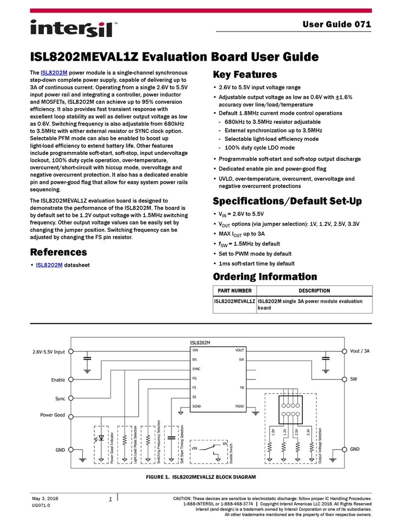
Intersil ISL70219ASEHEV1Z User manual
Other Intersil Motherboard manuals
Intersil
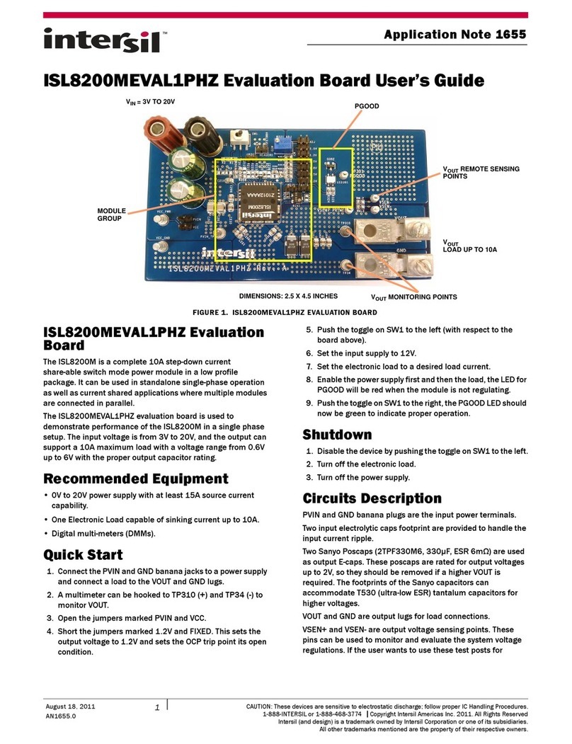
Intersil ISL8200MEVAL1PHZ User manual
Intersil
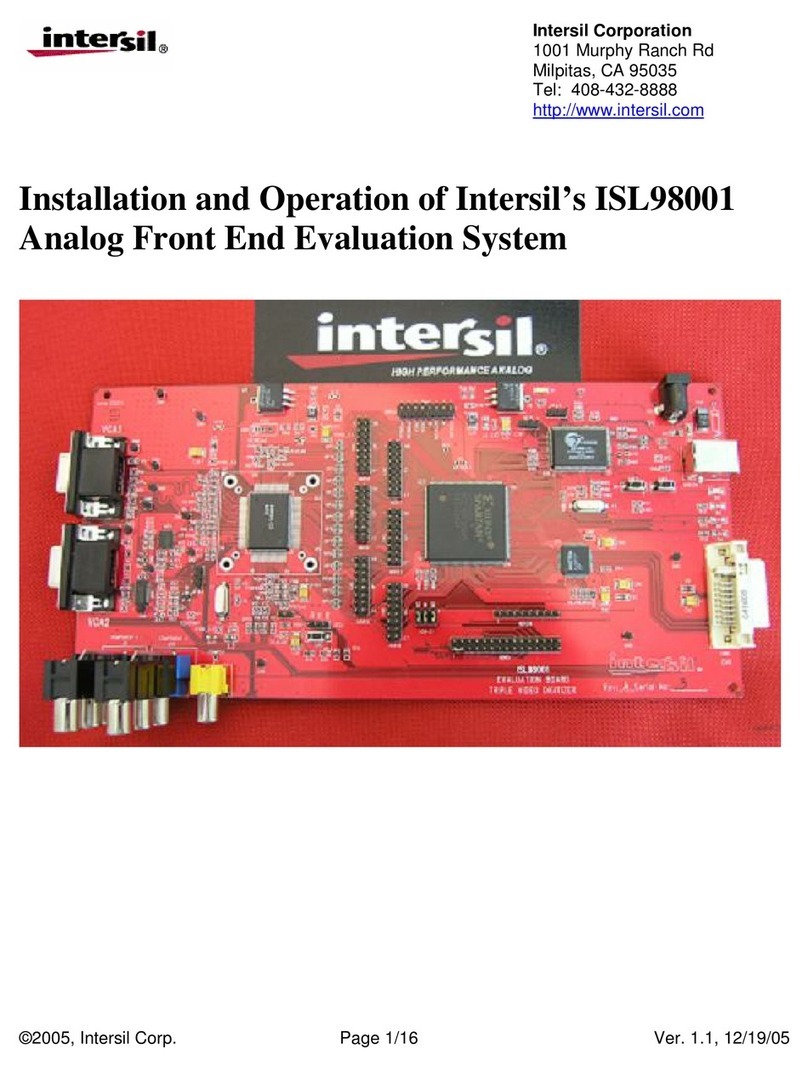
Intersil ISL98001 Owner's manual

Intersil
Intersil HIP4086 User manual

Intersil
Intersil ISL78171EVAL1Z User manual
Intersil
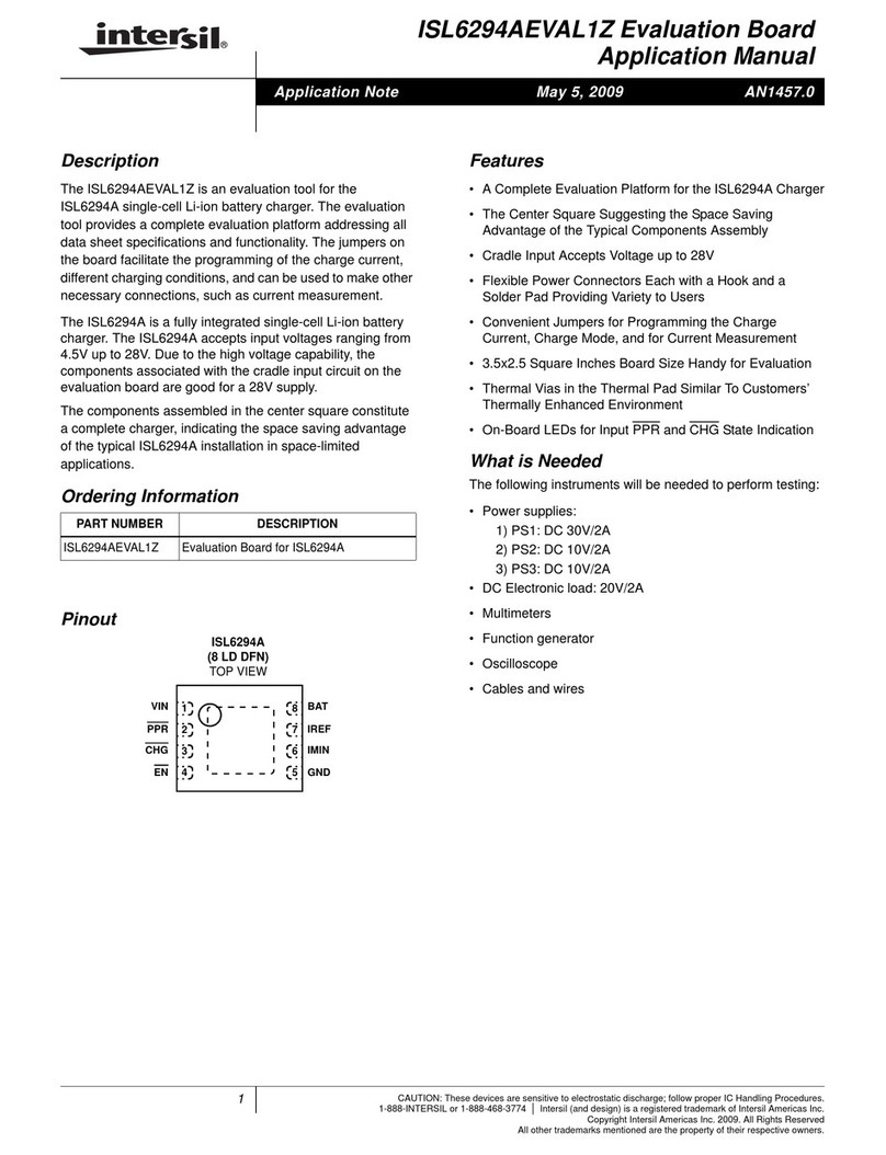
Intersil ISL6294AEVAL1Z Instructions for use
Intersil
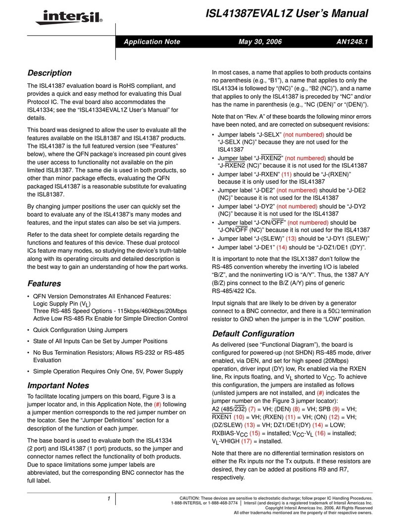
Intersil ISL41387EVAL1Z User manual
Intersil
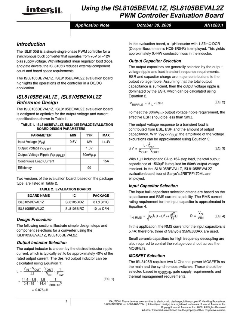
Intersil ISL8105BEVAL1Z User manual
Intersil
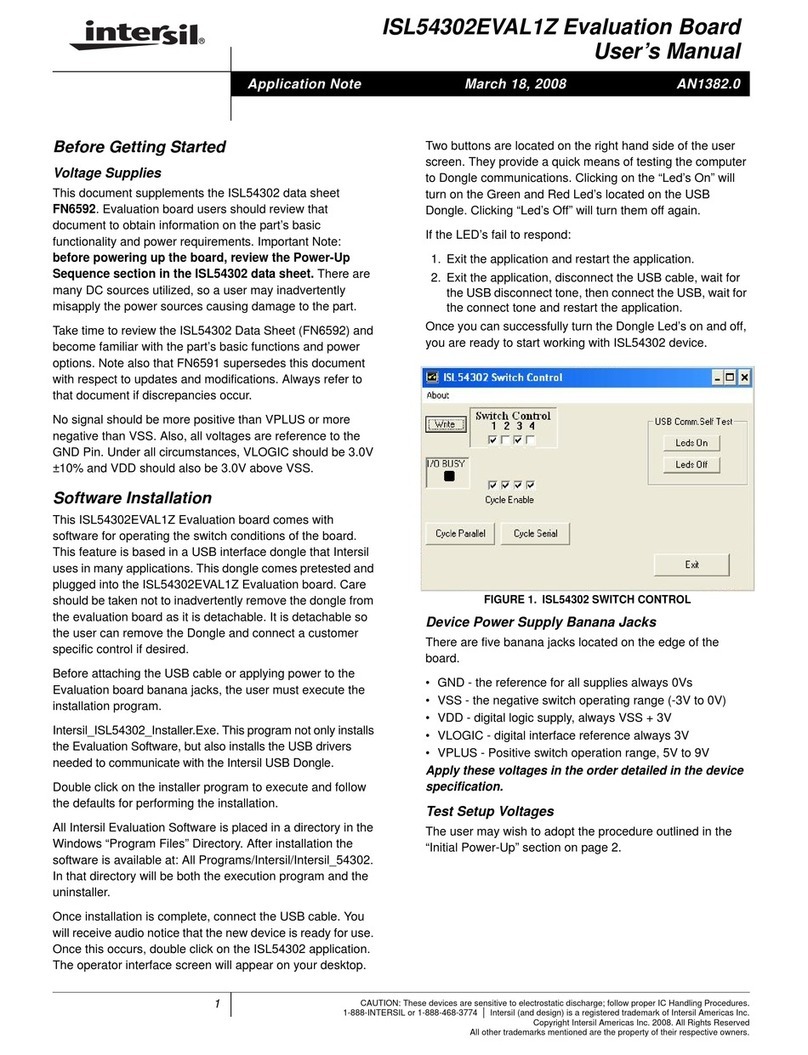
Intersil ISL54302EVAL1Z User manual

Intersil
Intersil ISL59442EVAL1 User manual
Intersil
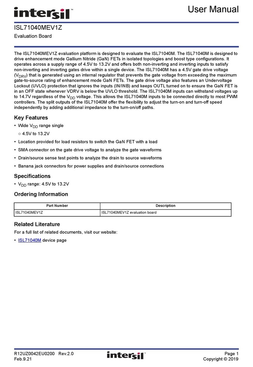
Intersil ISL71040MEV1Z User manual
Intersil
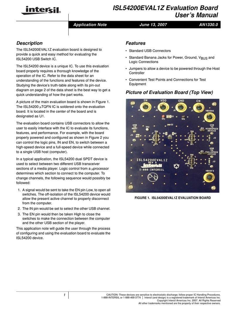
Intersil ISL54200EVAL1Z User manual
Intersil
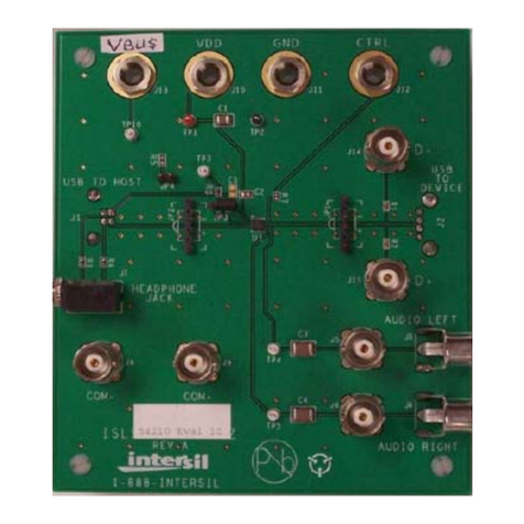
Intersil ISL54210EVAL1Z User manual
Intersil
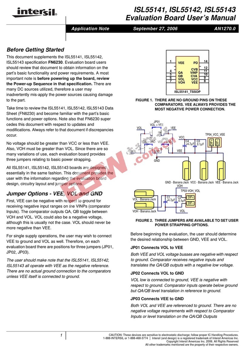
Intersil ISL55141 User manual
Intersil
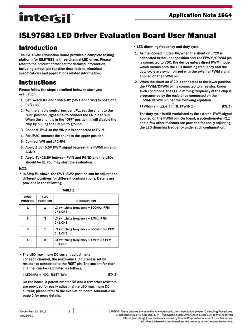
Intersil ISL97683 User manual
Intersil
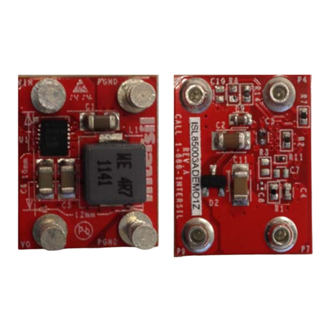
Intersil ISL85003DEMO1Z User manual

Intersil
Intersil ISL282x6EVAL1Z User manual
Intersil
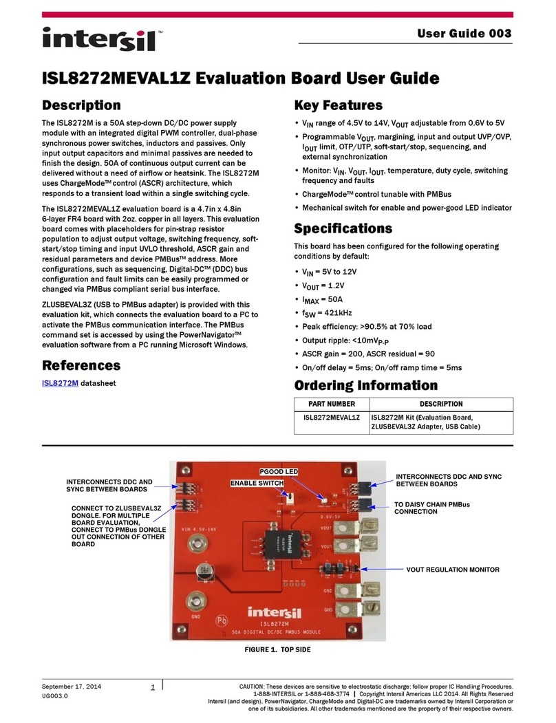
Intersil ISL8272MEVAL1Z User manual
Intersil
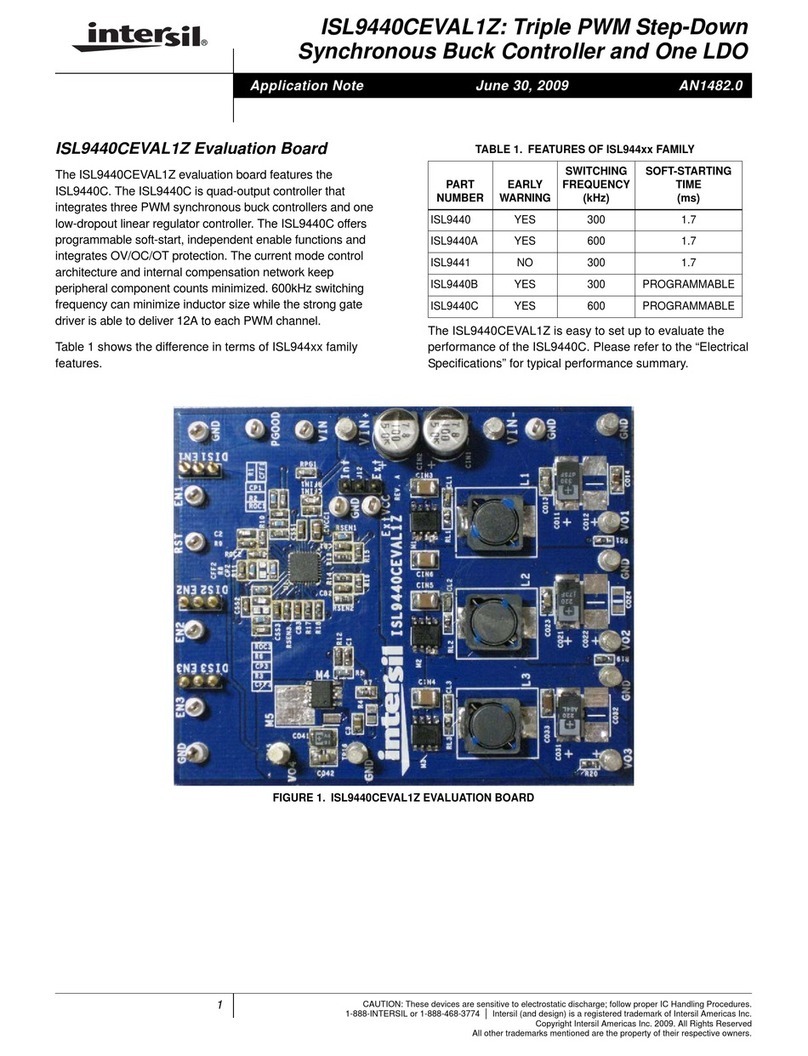
Intersil ISL9440CEVAL1Z Installation and operating instructions
Intersil
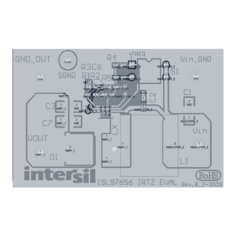
Intersil ISL97656IRTZEVALZ Instructions for use
Intersil
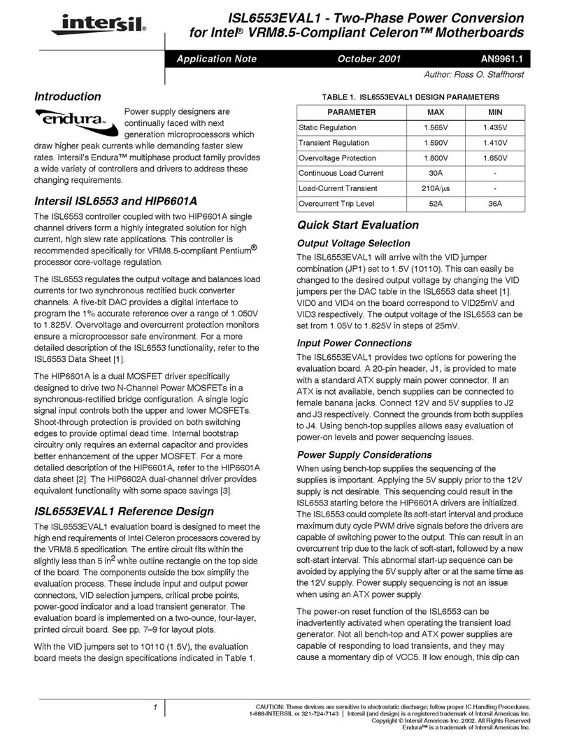
Intersil ISL6553EVAL1 Installation and operating instructions

