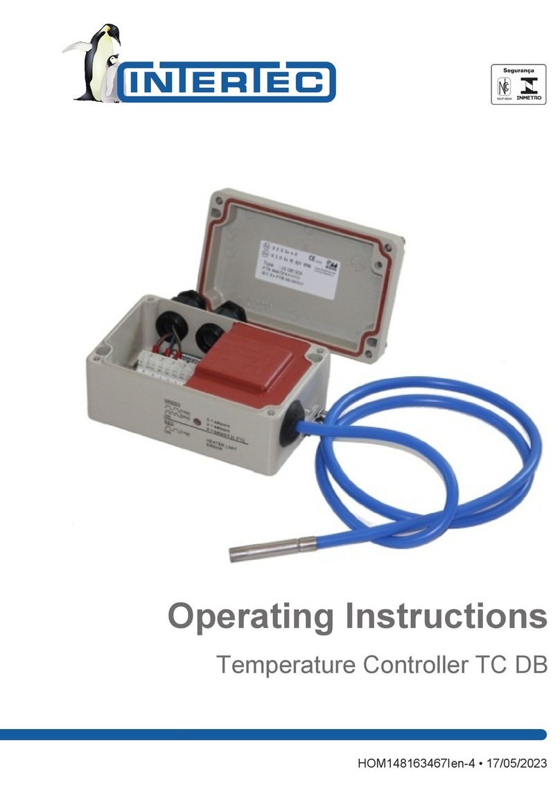
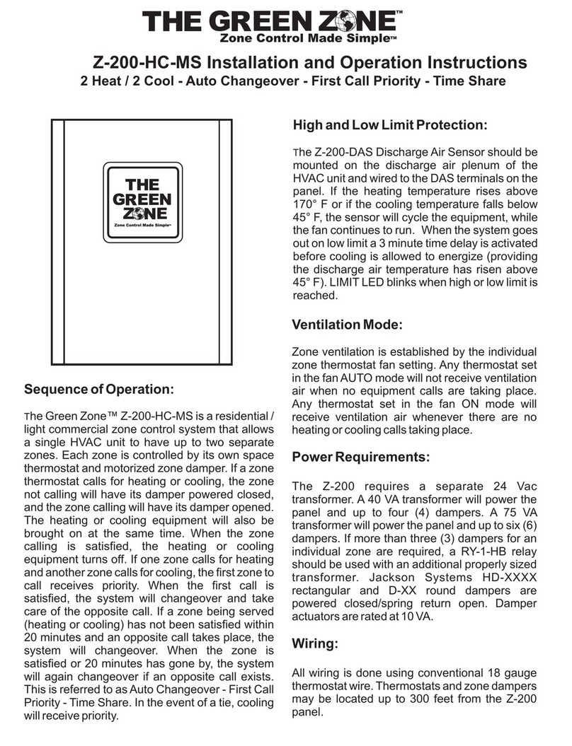
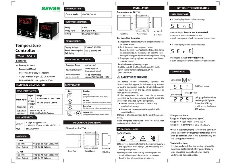
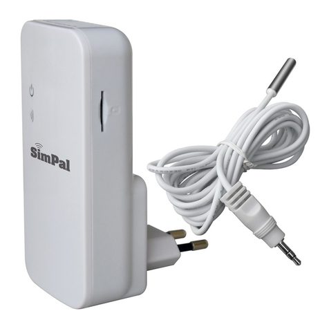
Intertec Data Systems TC D User manual

Operating Instructions
Temperature Controller TC D
HOM107626379Ien-7 • 19/10/2020

www.intertec.info
Page 2 / 6 HOM107626379Ien-7
INTERTEC-Hess GmbH · Raffineriestr. 8 · 93333 Neustadt/Donau · Germany · +49 9445 9532-0 · [email protected]
Table of contents
1 Use ...........................................................................................................................................................................3
2 Explanation of symbols for warnings and signal words .................................................................................... 3
3 Installation Instructions ......................................................................................................................................... 3
4 Device Description .................................................................................................................................................3
5 Technical Data ........................................................................................................................................................3
6 Installation...............................................................................................................................................................4
7 Connection..............................................................................................................................................................4
8 Test software and setup software......................................................................................................................... 5
9 Maintenance............................................................................................................................................................5
10 Troubleshooting .....................................................................................................................................................5
11 Deinstallation .........................................................................................................................................................5
12 Disposal...................................................................................................................................................................5
13 EU declaration of conformity ................................................................................................................................ 5
14 Further information and service ........................................................................................................................... 6

www.intertec.info
Operating Instructions Temperature Controller TC D
HOM107626379Ien-7 Page 3 / 6
INTERTEC-Hess GmbH · Raffineriestr. 8 · 93333 Neustadt/Donau · Germany · +49 9445 9532-0 · [email protected]
1 Use
The digital temperature controller TC D... is
manufactured according to the guideline 2014/34/EU
and is intended, among other things, for controlling the
temperature of enclosures, cabinets or heat trace
cables.
The TC D... is delivered with the index "J" and can be
switched together on site with the heating source to be
regulated. It is equipped with an external sensor -index
"E"- and with the HI version can be provided with an
additional sensor connection for controlling the heating
source.
The temperature controller approved in Ex zone 1 and 2
for device categories G/ D, in temperature class T4.
2 Explanation of symbols for warnings
and signal words
The safety information warns the user about risks and
provide information on how risks can be avoided.
Safety information can be found at the start of the
chapter before the instructions which may lead to a
hazardous situation. Additional safety information can be
found at the beginning of this manual.
Safety instructions which must be adhered to are
highlighted as follows:
DANGER
DANGER
This sign is warning about an extremely hazardous
situation which, if not heeded, will lead to death or
serious irreversible injury.
WARNING
WARNING
This sign is warning about a hazardous situation which,
if not heeded, may lead to death or serious irreversible
injury.
CAUTION
NOTICE
This sign is warning about a hazardous situation which,
if not heeded, may lead to slight, reversible injury.
NOTICE
NOTE
It is essential to pay attention to this safety advice as you
may otherwise incur material damage.
INFO
Important notes and useful additional information.
3 Installation Instructions
INFO
The device may only be connected up and secured by a
trained person, taking into account the "rated voltage"
and "rated current" specified on the nameplate.
For mounting in hazardous dust areas, certified
components must be used. The connecting cables must
have a fixed installation and must be protected
mechanically.
NOTICE
Only heat-resistant connecting cables may be used.
4 Device Description
The RS 485 interface allows the interconnection of
devices in field bus networks and parameterization at a
PC via the Modbus RTU protocol. The set temperature is
adjustable in 1°C increments.
The device has a two-colour LED light on the side for
determining the status visually.
The digital temperature controller has three analogue
inputs that can each be used as an actual value
encoder:
• An external intrinsically safe KTY temperature
sensor for measuring and controlling the temperature
• An internal temperature sensor for monitoring the
housing
• Optional: The NTC sensor of the heating coil for the
electronic temperature limit
5 Technical Data
Rated voltage max. 250 V AC

www.intertec.info
Operating Instructions Temperature Controller TC D
Page 4 / 6 HOM107626379Ien-7
INTERTEC-Hess GmbH · Raffineriestr. 8 · 93333 Neustadt/Donau · Germany · +49 9445 9532-0 · [email protected]
Permitted operating voltage max. 275 V AC
Rated current (in compliance
with VDE 0298)
max. 10 A
Ambient temperature - 50 to + 80 °C
Operating temperature at
nominal operation
- 25 to + 80 °C
Protection class IP66
Installation position any position
Switching capacity 10 A
Minimum load 30 W/ 60 W
Cable gland 2 x M20 / optional 3 x
M20
Material Seawater-proof
aluminium, powder-
coated
Dimensions 57 x 125 x 80 mm
Mean Time Before Failure 50.000 h
Storage temperature - 50 to + 80 °C
INFO
You will find the precise technical data for your
instrument on the label.
Rated voltage/Operating voltage
Illustration1: Example: TC D label
6 Installation
NOTICE
Risk of overheating
The controller housing may only be mounted at a place
where 80°C is not exceeded.
If higher temperatures should be controlled, the
intrinsically safe external sensors have to be attached to
the place to be controlled and the controller housing
outside the heated area.
At higher temperatures, the controller must no longer be
impinged with full power.
Room
temperature
up to
Imax 120 V AC 230 V AC
+40°C 10 A 1200 W 2300 W
+50°C 8.7 A 1050 W 2000 W
+65°C 6.5 A 780 W 1500 W
+80°C 4.4 A 530 W 1000 W
Imin = 250 mA
At temperatures below -25°C, the controller switches
over to the "cold-start mode". At the same time, the
output switches to 100% power until the circuit board
exceeds the temperature of -20°C. Thus, in very cold
climatic conditions, it is necessary to ensure that the
connected heating also heats the controller. If a
permanent operating temperature greater than -25°C
cannot be reached, the controller must be heated
separately.
7 Connection
INFO
The device may only be connected up and secured by a
trained person, taking into account the "rated voltage"
and "rated current" specified on the nameplate.
Each heater with integrated TS thermostat must be
preceded by a 10 A fuse or a motor protection switch
with short-circuit and thermal quick release (set to 10 A)
as short-circuit protection. When using a heater without
integrated thermostat, the fuse protection can be
selected according to the cross-section of the supply
cable.
Additional equipotential bonding is required. The
terminal block designated for this purpose has the
ground sign.

www.intertec.info
Operating Instructions Temperature Controller TC D
HOM107626379Ien-7 Page 5 / 6
INTERTEC-Hess GmbH · Raffineriestr. 8 · 93333 Neustadt/Donau · Germany · +49 9445 9532-0 · [email protected]
1 2 3 4 5 6 7 8 9 10 11 12 13
L
N
PE
NTC
RS 485
F1
TC DIGITAL
CP...THERM...HI
external sensor
br=brown bl=blue ye/gn=yellow/green bk=black gr=grey
bl br gn/ye gr bk
+
A
B
Ground
Illustration2: Temperature controller TC digital circuit diagram
8 Test software and setup software
If you have ordered the "SMART HEATER software" as
well, then please read the "TC SMART Modbus
Software" operating instructions for individually setting
the parameters and recording the data.
9 Maintenance
The design of the device does not require any
maintenance.
Functional and safety test intervals can be freely
selected by the operator in accordance with the
applicable regulations.
Repairs may only be carried out by the manufacturer in
the factory.
All components have to be kept clean and free of dust
and harmful substances that could lead to excessive
temperature rise.
In the dust Ex area, the applicable requirements of EN
60079-17 and EN 60079-19 must be complied with.
10 Troubleshooting
In the case of failure of the temperature controller or
performance fluctuations, please check the operating
conditions. See also: Installation [}Page4].
If the device is defective, it must be removed and sent
back to the manufacturer for repair.
11 Deinstallation
Disassembly may only be carried out by a trained
person.
DANGER
Risk of fatal injury from electric current!
If contact is made with live components, there is the risk
of fatal injury.
For this reason, switch off the voltage supply, secure
against being switched on again and check that no more
voltage is present.
Disconnect connection line from the clamps and from the
connection socket, disconnect device from bracket and
remove it.
12 Disposal
Disassemble the components of the product, taking the
applicable local labour protection and environmental
regulations into consideration and make sure that the
components are recycled:
• Scrap metal
• Send plastic elements to recycling
• Sort other components according to their material
properties and dispose of them.
NOTICE
Environmental damage may be caused if
disposed of incorrectly!
Electrical scrap and electronics components are subject
to hazardous waste treatment and must only be
disposed of by certified specialists!
The local community authorities or specialist waste
disposal companies can provide information on
environmentally friendly disposal.
13 EU declaration of conformity

www.intertec.info
Operating Instructions Temperature Controller TC D
Page 6 / 6 HOM107626379Ien-7
INTERTEC-Hess GmbH · Raffineriestr. 8 · 93333 Neustadt/Donau · Germany · +49 9445 9532-0 · [email protected]
The manufacturer, INTERTEC-Hess GmbH,
Raffineriestrasse 8, 93333 Neustadt/Donau, Germany,
hereby declares in sole responsibility that the product
Product / Type designation:
TC D
complies with the provisions of the following directives
2014/34/EU (ATEX), 2014/30/EU (EMC), 2011/65/EU
(RoHS), 2012/19/EU (WEEE) complies with the following
standards, harmonized standards, where appropriate
and/or standardized documents:
EN IEC 60529:1991+A1:2000+A2:2013
EN IEC 60079-0:2014
EN IEC 60079-1:2014
EN IEC 60079-11:2012
EN IEC 60079-18:2015
EN IEC 60079-31:2014
EN IEC 60079-7:2015
EN IEC 61000-6-4:2007+A1:2011
Harmonized Standard (RoHS):
DIN EN IEC 63000:2019
Designation:
0102
II 2 G Ex e mb [ib] IIC T4
II 2 D Ex tD A21 IP66 T130°C
PTB 04 ATEX 2022 X
Neustadt, Sept. 10th, 2019
Dipl.-Ing. Martin Hess, Managing Director
14 Further information and service
If the information contained in this instruction manual
should not be sufficient in any way, then INTERTEC
would be glad to be at your disposal to provide further
information and service.
Please contact your INTERTEC contact person or
directly contact
INTERTEC-Hess GmbH
Raffineriestr. 8
93333 Neustadt/Donau
Germany
Phone: +49 9445 9532-0
e-mail: [email protected]
Website: www.intertec.info
Warranty
The legally defined warranties and warranty periods of
24 months are applicable to our scope of supply and
services.
You will find more detailed information in the
manufacturer warranty from INTERTEC for heating
systems and accessories.
These instructions do not claim to take all
designs, options or changes into
consideration, even in association with
installation, operation or maintenance.
INTERTEC does not accept responsibility
for providing information about changes
made retrospectively.
Table of contents
Other Intertec Data Systems Temperature Controllers manuals
Popular Temperature Controllers manuals by other brands
Auber Instruments
Auber Instruments WSD-1200GPH quick guide

Fike
Fike FIK-2351T Installation and maintenance instructions
Viessmann
Viessmann VITOTROL 100 Installation instructions for contractors
Sorel
Sorel STDC1 Installation and operating instructions
Magnum
Magnum M9-RTS1 Mounting instructions
Innovative instruments
Innovative instruments i-therm AI-7442 User's operating manual
