Brake Timing Test CERTIFIER 912
# 87005 REV. 2.0.0 – OCT. 2013 Page 3 of 9
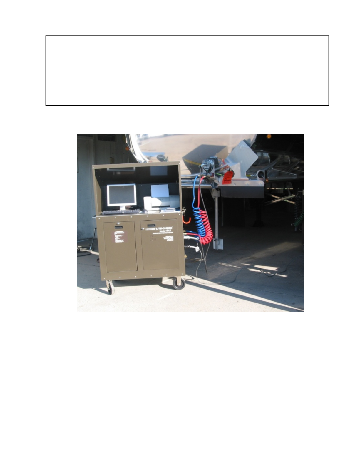
CERTIFIER 912 Brake Timing Test
Entering the Vehicle Information
1. Input the VIN # of the vehicle
2. Input the OPERATOR name
3. (Option) Input the CUSTOMER name
4. (Option) Input the ORDER#
5. (Option) Input up to 6 USER DEFINED FIELDS identifying type of trailer, # of
axles, ABS, brake system, and etc..
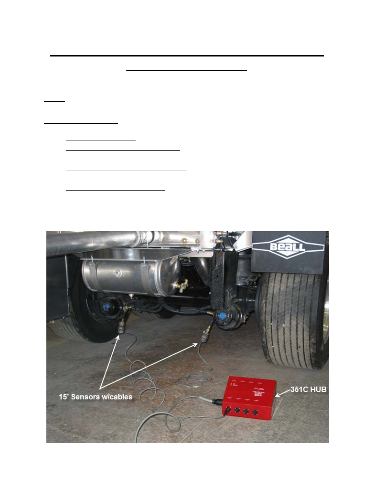
Setting up for 121 brake testing
Non-Towing style trailer
1. Insert a minimum of 1 transducer in the Service Brake chamber, and 1
transducer in the Emergency Brake chamber furthest from the relay valve.
Towing style trailer
1. Insert a minimum of 1 transducer in the Service Brake chamber, and 1
transducer in the Emergency Brake chamber furthest from the relay valve.
2. With a 50 c.i. canister connected to both of the output glad hands, connect a
transducer in the Service output.
In the CERTIFER software, go to the HUB tab and label the transducers by their
location. EMERGENCY, SERVICE, or DOLLY, 1,2,3, and etc.
*If it can be proven through engineering analysis that other brake chambers are closer
to valve or have less air fittings than the chamber being tested, then it is sufficient.
**If there are more axles, lift axles, or any other reason why there would be additional
hose length or air fittings required, then additional transducers should be inserted into
those brake chambers.
A calibration test should be performed at least once a week. This file may be used, in
addition to final trailer reports, to prove compliance of the tester and the trailer.
Note: These instructions are assuming that the CERTIFIER 912 is powered on, properly
calibrated to meet 121 standards (see Calibration and Self-Test of CERTIFIER 912),
and the “Vehicle Information” tab has been completed.