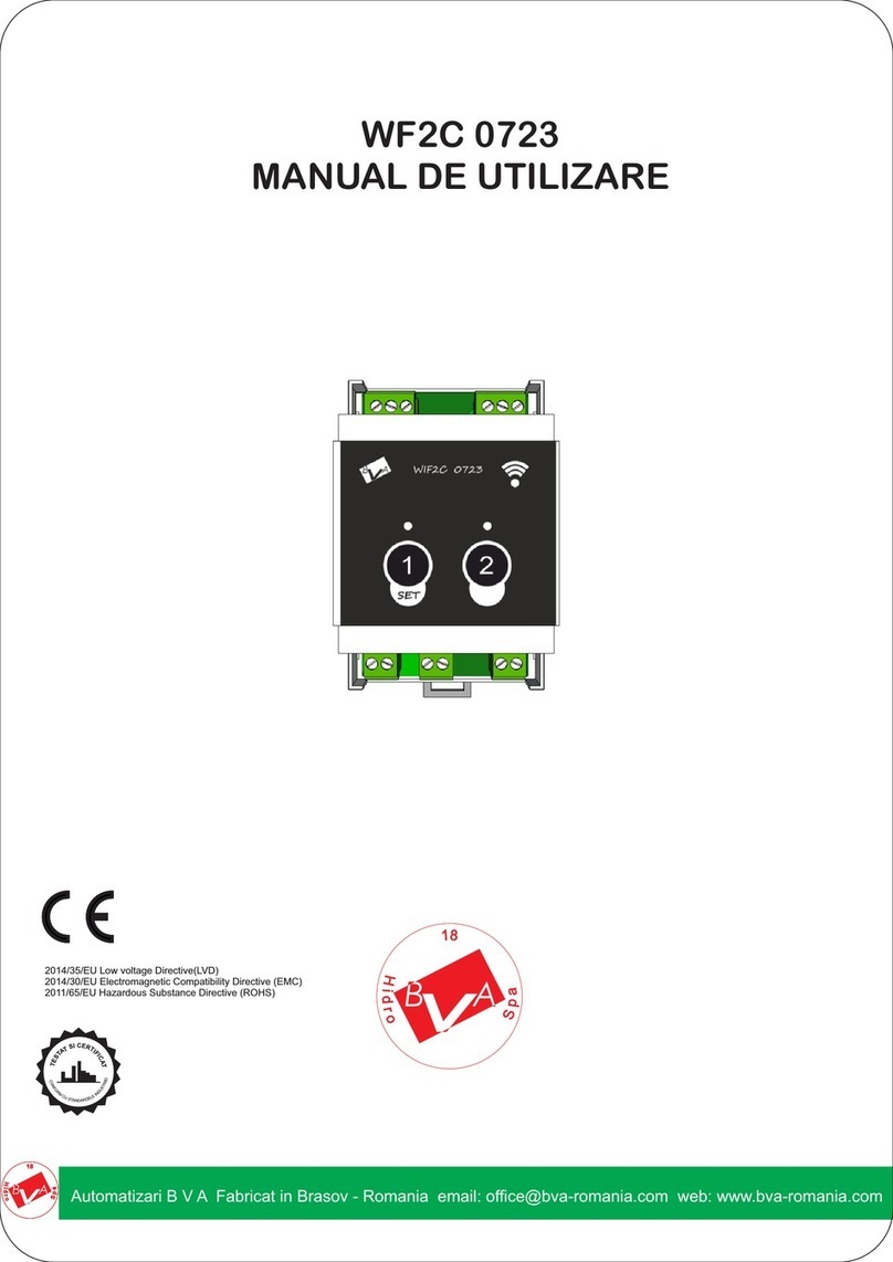
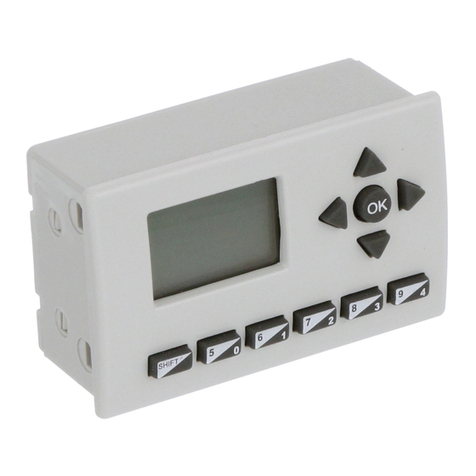
Intiel VENTOCONTROL User manual

2
1. Application
The device is designed to keep the air temperature in ventilation and air conditioning systems depending on the needs of the
premises.
2. Operation
The controller can manage the following units of the system:
- Water heating and cooling section, with proportionate actuators of the three-way valves through two analog signal 0 - 10V
for heating and 10 - 0V for cooling.
- Electrical section, divided into up to six levels, each level is controlled by relay output.
- Air section by incoming and outgoing fan and signal 0 - 10V for management of frequency inverters for fans.
Water heating and cooling section:
The zone of regulation "Zone_reg" is immediately before setpoint temperature in air duct "T_set". When the measured
temperature is less than the temperature determined by the zone of regulation "Zone_reg", to the actuator for "heating" is fed
maximum control signal 10V, and to the actuator for "cooling" minimal signal 0V. When reaching the the zone of regulation
will begin change of both control signal for heating and cooling (0 - 10V and 10 - 0V). The change of the signal is present until
the temperature is in the zone of regulation. When measured temperature is higher than the set temperature to the actuator for
"heating" is fed minimal control signal 0V, and the actuator to a "cooling" maximum signal 10V.
When closing the contact at the input for frost protection, output for heating is fed maximum signal 10V, and output for
cooling minimum 0V and both the fan is switched off immediately
Electric heating section:
When the measured temperature is less than the temperature determined by the the zone of regulation "Zone_reg", is
switched on all the levels and fed all the installed power.
When reaching the zone of regulation will start exclude part of the levels as the forward power is proportionality of the
temperature difference between the set and measured temperature in air duct (T_set - T). When the measured temperature is
higher than setpoint, all levels are switched off and do not transmit power.
When opening the contact from the input for block thermostat or input for a lack of air flow is immediately disconnected all
heaters.
Air section:
The device can manage incoming and outgoing fan, as the suction starts with 10 seconds delay.
Instead, fans may be used and two-position air valves. The controller is able to monitor the operating hours of the fans in
order to replace the filters after extended operation.
Also, the device can control and frequency inverter or speed regulator via an analog signal (0 - 10V or 10 - 0V) and signal
"stop" ( "open collector" - logical level 0V). (See programming "Service Settings" and "Specifications")
Change the fan speed depends on the temperature in air duct. The zone of regulation "Zone_reg" ". When the measured
temperature is less than the temperature determined by the zone of regulation "Zone_reg", is fed a control signal for the
minimum speed.
When opening the contact from the entrance to minimum flow, regardless of temperature given a signal for minimum
speed.
When the system is in stop mode fans remain working. another 60 sec., in order to prevent
overheating in the heating section.
Т, °C
Т_set
T
U,V
10
zone_reg
Т_set - zone_reg
Т, °C
T
P,%
100
zone_reg
Т_set
Т_set - zone_reg
50
Т, °C
T
n, min-1
max
zone_reg
Т_set
Т_set - zone_reg
min

3
Restrictions on temperature:
- Minimum setting of the temperature of the supply air;
- Maximum setting of the temperature of the supply air;
The minimum and maximum set the temperature in air duct define the limits of supply air to the premises. (See programming
"Service Settings")
3. Front panel
1 - indication;
2 - button for change "ahead";
3 - button for change "back";
4 - button to enter / exit the programming mode, start / stop (on hold for 5 sec .);
5 - indicator for working input fan;
6 - indicator for working output fan;
In the basic state the display shows the following parameters:
- T_set - set supply air temperature;
- T - current supply air temperature
- R - currently exploited power of the heating section;
4. Programming
When the controller is turned off, you can not move to programming and the display shows one of the following messages.
or
Attention! The controller can be switched on and off from the front panel or remote control input. The controller turns off
regardless of where there are stop signals, but can be switched only when both places have command START.
Depending on the message, the controller can be switched on:
- On message "System is off from external sw" - open socket connected to the inputs for remote control. (See programming
"Wiring and technical characteristics")
- On message "System is off from internal sw" - press and hold for 5 seconds. button "".
After switching displays the current mode "Ventilation" or "Heating" and can move on.
4.1 Manually setting the supply air temperature
With buttons "" or "" scroll until the display shows the set and the measured value:
Press "" to enter the programming mode, then the value of the assignment flashes. With buttons "" or "" may make
changes from "T_set_min" to "T_set_max". (See programming "Service Settings")
To confirm the changes again press "" or wait about 10 seconds for automatic recording.
4.2Formation of the seting by the room thermostat or room temperature.
4.2.1 Formation of the seting by the room thermostat
The room thermostats must be of analog type output 0 (4) - 20 mA.
The setting is automatically replaced by the "T_set_min" to "T_set_max" as a function of current of the room thermostat.
Display shows the following information:
(See programming "Service Settings")
T_set ...°C
T ...° C Р...%
System is off
from external sw
System is off
from internal sw
T_set … ° T …°
Rreg…mA P…%

4
4.2.2 Formation of the seting by the room temperature.
In this case, the converter is required (Pt1000 to 0 (4) - 20mA), which connects the terminals of the room thermostat.
The setting is automatically replaced by the "T_set_min" to "T_set_max" as a function of the room temperature. Maximum
setting is reached at measured room temperature less than 3 ° from the set and the minimum at equal or greater than the set.
Display shows the following information:
4.3Mode selection at work. With buttons "" or "" scroll until the display shows:
Press "" to enter the programming mode, then the value of the assignment flashes. With buttons "" or "" may make
changes from „Ventilation” and „Heating”. When the mode is "Ventilation" is not allowed to work the heating section.
4.4 Information about warning messages.
С With buttons "" or "" scroll until the display shows:
Where no fault signal is displayed above message:
Upon receipt of a a signal for failure showing the following messages:
- Activated blocking thermostat or appliance for lack of air flow
- Activated frost thermostat on the water section
- Reached hours of work to change air filters
After replacing the filters is necessary to reset the time for the next shift. Pressing "", appears "Reset time Fan" "No /
Yes" to choose "Yes".
4.5 Service settings.
С With buttons "" or "" scroll until the display shows:
Press "" of the indication will be a message appears for a password and the value after which it flashes:
С With buttons "" or "" scroll until the display shows 123, then press "". When a wrong password is displayed for about
10 seconds message:
4.5.1 Maximum temperature of air supplied to the premises
If correct password on the indication message appears maximum temperature value and then it flashes:
With buttons "" or "" may make changes from 40 to 90° C. To confirm the changes again press "" and go to the next
setting.
4.5.2 Minimum temperature of air supplied to the premises
On the indication message appears maximum temperature value and then it flashes:
With buttons "" or "" may make changes from 5 to 25° C. To confirm the changes again press "" and go to the next
setting.
Messages
Status is OK!
ATTENTION!
Overheating or no air flow
Service Set
for technicians
Service Set
Password: …
Service Set
Disable Wait…
Service Set
T_set_max … °C
Service Set
T_set_min … °C
Select regime
…
ATTENTION!
Very cool water
T_set … ° Tr …°
T … ° P…%
ATTENTION!
Replace Filter

5
4.5.3 Selecting the analog signal for the regulator of speed.
On the indication message appears maximum temperature value and then it flashes:
With buttons "" or "" may make changes from 0 –10V or 10-0V. To confirm the changes again press "" and go to the
next setting.
4.5.4 Choosing how to regulate climate system.
On the indication message appears:
With buttons "" or "" may make changes: „Heater”, “Servo” or “Servo+Heat”.
"Heater" - work outputs of heating and water section simultaneously.
"Servo" - work only outlets for water section.
"Servo + Heat" - work outputs of heating and water section, a heating section works only ½ of the zone of regulation and the
water continues until reaching the T-set.
To confirm the changes again press "" and go to the next setting.
4.5.5 Selection of maximum grades for the heating section.
On the indication message appears:
With buttons "" or "" may make changes from 1 up to 6
To confirm the changes again press "" and go to the next setting.
4.5.6 Zone of regulation.
On the indication message appears maximum temperature value and then it flashes:
With buttons "" or "" may make changes from 1 up to 15°С. This selects how many degrees before reaching the T-set. to
begin reducing the number the levels of the heating section, change control signals for proportional actuators of the water
section and speed drives for fans.
To confirm the changes again press "" and go to the next setting.
4.5.7 Coefficient for D regulator heaters.
On the indication message appears maximum temperature value and then it flashes:
With buttons "" or "" may make changes from 1 up to 3
To confirm the changes again press "" and go to the next setting.
4.5.7 Formation of the setting.
On the indication message appears maximum temperature value and then it flashes:
With buttons "" or "" may make changes between: Manual setting (Manual), by room thermostat (Room_reg) or room
temperature (T_room). At T_room need additional device (converter Pt1000 to 0 (4) - 20mA), which connects to the entrance
of a room thermostat.
To confirm the changes again press ""and go to the next setting.
4.5.8 Rotation of relay outputs.
On the indication message appears maximum temperature value and then it flashes:
With buttons "" or "" may make changes between: (Enable) or (Disable).
To confirm the changes again press ""and go to the next setting.
4.5.9 Period to change filters.
On the indication message appears maximum temperature value and then it flashes:
With buttons "" or "" may make changes from 0 up to 30000 h. At 0 monitoring of operating hours is inactive.
To confirm the changes again press ""and go to the next setting.
Service Set
vent_out …
Service Set
Num. heaters …
Service Set
Zone_reg … °C
Service Set
Control ……..
Service Set
K_diff. …
Service Set
Rel_rot ……..
Service Set
Output …
Service Set
ReplFilt ……h

6
4.5.9 Exit from service settings.
With buttons "" or "" may make changes between: „Exit or “Return”
On the indication message:
To confirm the changes again press ""
6. Electrical connection and technical data
Technical data:
Power supply ~ 230V / 50Hz
Outputs of heaters 6 pcs. x ~ 230V / 1.5kW
Outputs Fan 2 pcs. x ~ 230V / 0.5kW
Sensor Pt 1000 temperature (-50 to +250 ° C)
Input room thermostat 4 - 20mA
Signal proportional valves 0 - 10V / max.20mA
Speed regulator
Control signal 0 - 10V / max.20mA
Stop - output "open collector" max. = 24V / 20mA
Measuring range -30 to +130 ° C
Measurement unit 1 ° C
Humidity up to 80%
Protection IP20
If the power of heaters and fans is greater than the indicated use auxiliary contactors, in which case the controller is
powered single phase, as the wiring phase is connected to the terminal 12, 17 and 22.
- Input for fire protection - the device is powered through the entrance for fire protection when not in use such terminals 9
and 10 should be placed bridge.
- The levels of the heating section are ON from 1 tu 6 in the figure, for the uniform loading of the phases.
- Remote Input –STOP at open contact between terminals 42 and 43, START at closed contact. When not in use between
terminals 42 and 43 should be placed bridge.
- input minimum flow - MIN. DEBIT at open contact between terminals 44 and 45. When not in use should be placed
bridge between terminals 44 and 45.
- Input for frost protection of water sections - at closed contact safety trip. When not in use not put anything on the terminals
40 and 41.
- Input device for flow sensor and blocking thermostat - at open contact is triggered to protect. When not in use must be
placed bridge between the terminals 36 and 37, 38 and 39.
Service Set
Exit or Return
1 2 3 4 5 6 7 8 9 10 11 12 13 14 15 16 17 18 19 20 21 22 23 24 25 26
AД
N
Speed
inverter
30 31 32 33 34 35 36 37 38 39 40 41 42 43 44 45 46 47 48 49 50 51 52
AД
GND
0-10V
Stop
+ -
- +
M
M
Proportional
valves
Heat.
Cool
Remote
input
frost
protection
Bocking
thermostat
Flow
sensor
Т въздуховод
Room
thermostat
-12V
4-20mA
GND
+12V
MIN. DEBIT
AP
AP
AP
INPUT FAN
OUT. FAN
fFre protection
R
S
T
Max. 1.5W
Max. 1.5kW
Max. 1.5kW
Max. 1.5kW
Max. 1.5kW
Max. 1.5kW
Max. 0.5kW
Max. 0.5kW
1
4
2
5
3
6
Converter
Pt1000(4) –20mA
4-20mA
GND
+12V

7
Service settings:
Password: 123
name
designation
limits
current value (notes)
Max. air
temperature
T_set_max.
40 –90 °C
Min. air
temperature
T_set_min.
5 –25 °C
Signal for
SPEED
DRIVE
Vent_out
0 –10V ; 10 –0V
Choice on
outputs
Output
Heater
Servo
Servo + Heat
Number of
grades
num. heaters
1 –6
Zone of
regulating
Zone_reg
5 –15 °C
Quotient D
K_diff.
1 –3
Formation
on
setting
Control
Manual
Room reg
T room
Rotation relay
Rel_rot
Disable /Enable
Changing the
filter
ReplFilt
0 –3000 h
7. Warranty
The warranty period is 24 months following the purchase date of the unit or its installation by an authorized
Engineering Company, but not exceeding 28 months after the production date. The warranty is extended to the malfunctions
that occur during the warranty period and are result of the production reasons or defective used parts.
The warranty does not relate to malfunctions corresponding to not-qualified installation, activities directed to the
product body interference, not regular storage or transport.
The repairs during the warranty period can be done after correct filling of the manufacturer warranty card
Warranty Card
Manufacturer: INTIEL
Product type
Controller for ventilation and air conditioning systems
type: VENTOCONTROL
Production number
Production date
Dealer confirmation
Purchase date
Invoice number
Dealer’s name, address and stamp
Seller’s name and signature
Table of contents
Other Intiel Controllers manuals
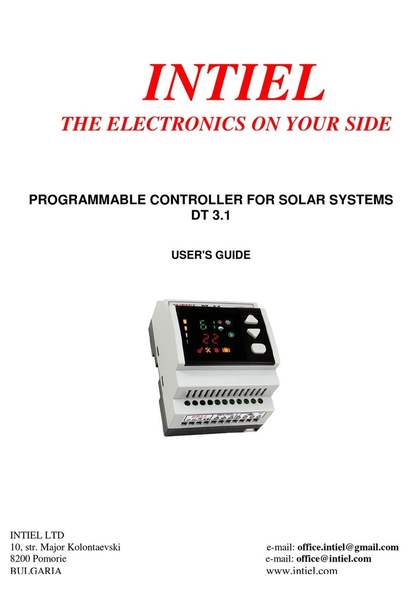
Intiel
Intiel DT-3.1 User manual
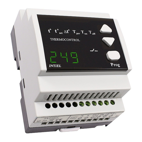
Intiel
Intiel TR-6.3 User manual
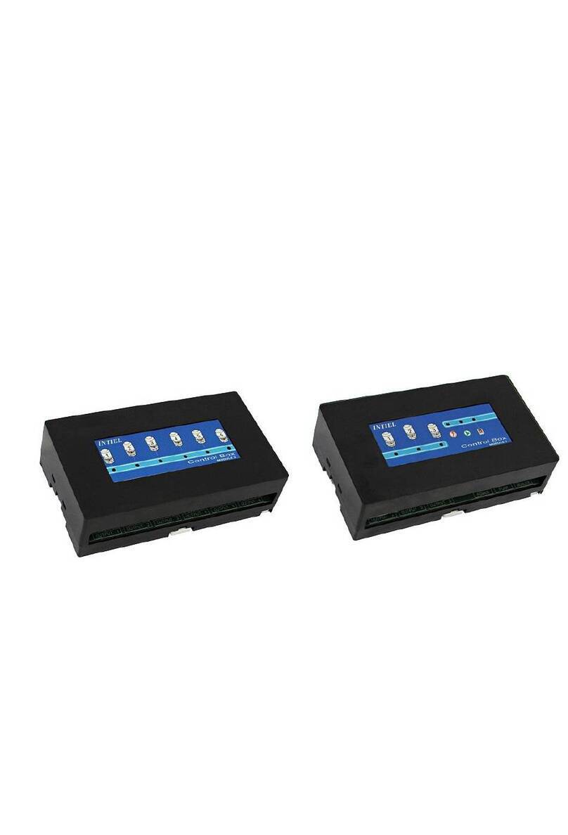
Intiel
Intiel MODUL 1 User manual
Intiel
Intiel PVBoiler User manual
Intiel
Intiel INT0193 User manual
Intiel
Intiel DT 3.2.2 User manual
Intiel
Intiel INT092F User manual
Intiel
Intiel Dynamic Boiler Controller User manual
Intiel
Intiel INT0140 User manual
Intiel
Intiel AQUA FILTER INT010 User manual

