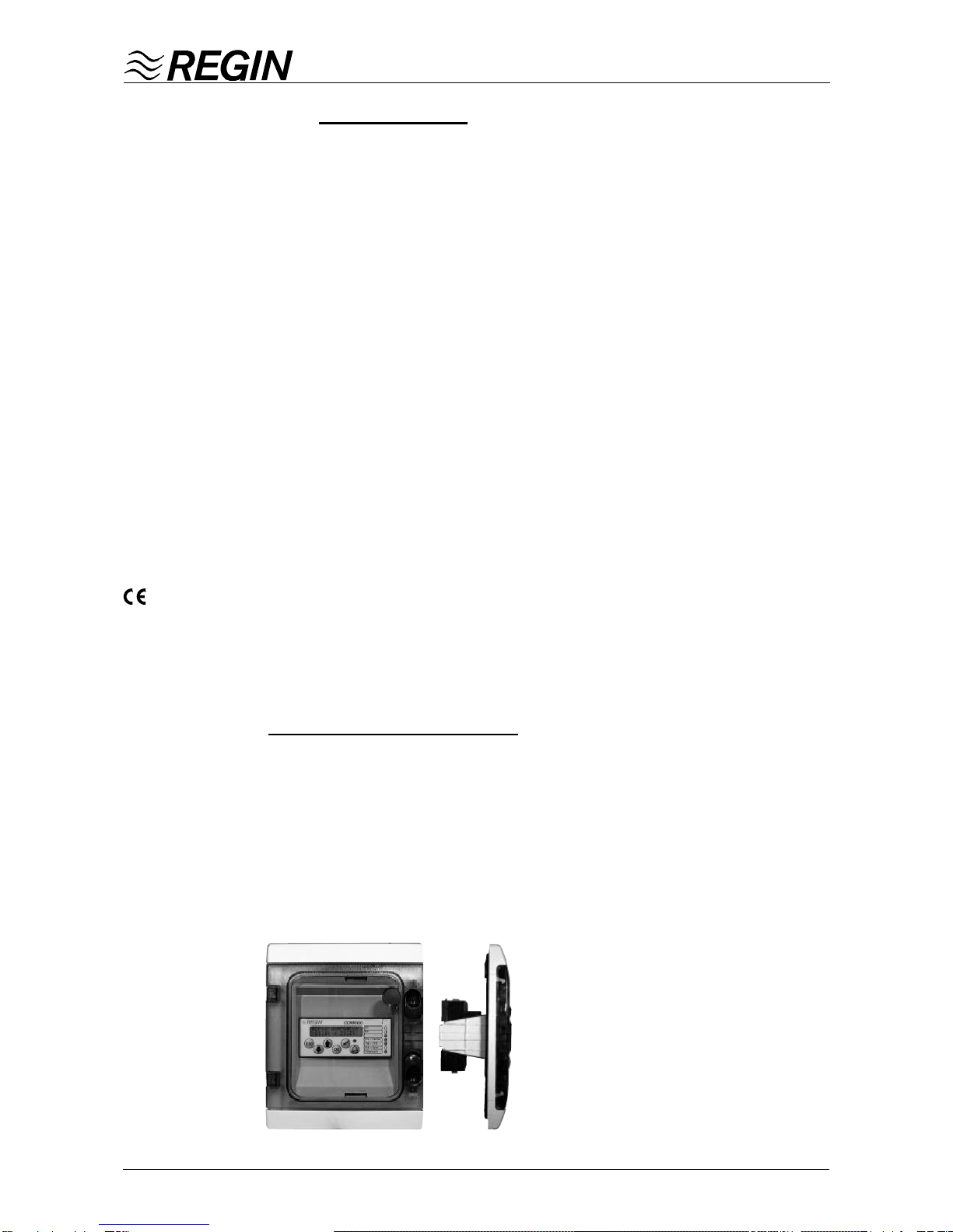
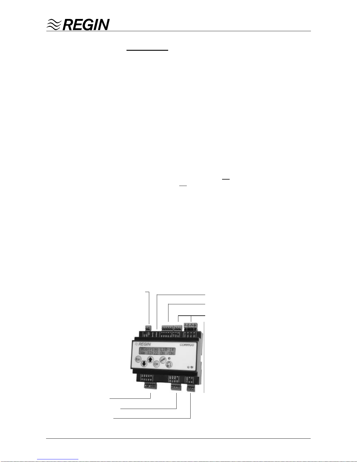
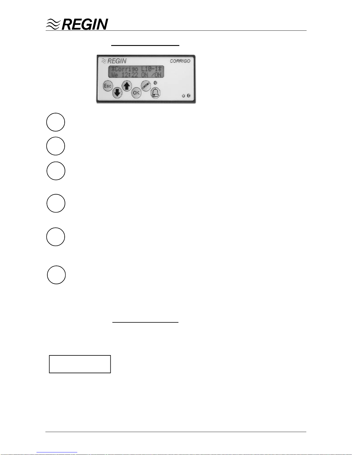
ManualCORRIGO L10 2002-11
Configuration
CORRIGO-L10 is adapted to the system at hand by selecting functions individually.All
configuration options are set using explanatory menu texts.
Configuration codes
There is also the option of setting parameters by means of two configuration codes.
Thisfunctionis particularly useful and timesaving when a number ofcontrollersare to
be configured in the same way.
The first thing to be shown when the configuration menu is opened is the setting of
the control function. Using the arrow up button the configuration code will be dis-
played,andthe arrow down button will give the parameters oftheother configurations
in plain text.
The code digits in the configuration code correspond to the script parameters below
in numerical sequence. This means that the first digit in CONFIG CODE determines
which control function the controller is to work with. The second digit refers to
sequence etc.
In front of the corresponding selection in the script parameters there is a digit which
corresponds to the code number in the configuration code. See the details below.
Guide for configuration code
There is also a special table to facilitate the choice of configuration code. This is
always supplied together with the CORRIGO L10 instruction sheet.
In the table all the configuration parameters are shown as well as the selections that
can be made. Basic selections are marked in bold type.
Bygoingthrough the parameters and filling in the appropriatefigurefor each
selection the configuration code can be obtained without difficulty. This can also act
as a protocol of settings for CORRIGO L10.
Automatic restart after changing
Whenoneormoreparametershavebeenchanged the controller will restart when the
userleavestheconfigurationmenu.
Exampleofaconfiguration
guide.
Control funct. ?
0 Suppl.air cnt?
Config Code
0501.0000.010 ?
CONFIGURATION-Corrigo L10 A B C D .EFGH. I JK
Config Code . .
AControlfunction
0. Supply air control 0
1. Supply air control with outdoortemp. compensation 1
2. Room control with cascaded supply air 2
3. Room control with min/max limitited supply air temperature 3
4. Room control with no supply air sensor 4
5. Supply air control/Room control. Outdoor temperature dependent 5
BOutput sequence Y1, Y2, Y3 (AO1, AO2, AO3)
0.Heat / - /- 0
1.Heat/ Cool / - 1
2.Heat / Damper/ - 2
3.Heat / Damper/ Cool 3
4.Heat/ Plate exchg. / - 4
5.Heat / Plateexchg. / Cool 5
6.Heat / Rotatingexchg. / - 6
7.Heat / Rotatingexchg. / Cool 7
8.Cool/ - / - 8
C Heater type
0. Water heater 0
1. Electric heater 1
D Frostguard (Only if Waterheater is selected)
0. Not activated 0
1.Y1 1
2.Y1 Automatic reset 2
E Shut-down mode (Only if Waterheater is selected)
0. No 0
1.Yes 1
FPumpstop(Onlyif Waterheater is selected)
0. No 0
1.Yes 1
GFunctionforAI1
0. Outdoor temperature sensor 0
1. External setpoint 1
HFunction for DI1
0.Fan malfunction alarm 0
1.Fan status 1
I FunctionforDI3
0. Not used 0
1. Timer for extended run (presence detector) 1
2. Pushbutton 2
3. Smoke detector alarm 3
4. External alarm 4
JFunctionforDI4
0. Not used 0
1. Frost build-up guard 1
2. Alarm rotating exchanger 2
3. Alarm chiller/cooler 3
4. Smoke detector alarm 4
5. External alarm 5
KFunction for DO1, DO2
0.-- / -- 0
1.DX1/ -- 1
2. -- / Frostguard interlock 2
3. DX1 / Frostguard interlock 3
4.DX1/DX2 4
5.DX Binary 5