IntraGrain Fuel Lock Personal User manual

www.fuellock.ca November 2021 Version 3.0 Page 2
CUSTOMER SUPPORT .................................................................................................................... 4
CERTIFICATIONS ............................................................................................................................ 5
MANUFACTURER’S WARRANTY ..................................................................................................... 6
HOW TO OBTAIN WARRANTY SERVICE ..........................................................................................................6
LIABILITY CLAUSES ........................................................................................................................ 7
SAFETY ........................................................................................................................................... 8
STANDARDS ..........................................................................................................................................................8
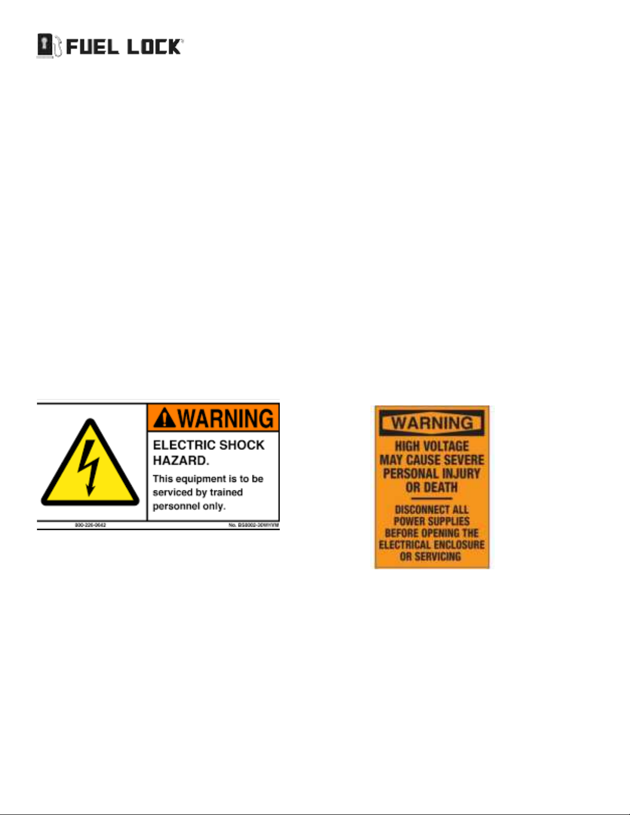
SAFETY INFORMATION ......................................................................................................................................9
ABOUT FUEL LOCK ....................................................................................................................... 10
APPLICATIONS ....................................................................................................................................................10
FEATURES ............................................................................................................................................................11
SPECIFICATIONS .......................................................................................................................... 13
FUEL LOCK INSTALLATION .......................................................................................................... 14
COMPONENTS ....................................................................................................................................................14
TOOLS REQUIRED ...............................................................................................................................................14
INSTALLATION PROCEDURE ...........................................................................................................................14
Connecting Fuel Lock To 120v Pumps ...........................................................................................................17
CONNECTING FUEL LOCK TO 240V PUMPS ................................................................................................18
FLOW METER - FUEL LOCK BUSINESS ......................................................................................... 20
INSTALLATION FLOW TEST ......................................................................................................... 22
SETTING A CUSTOM PULSE RATE .................................................................................................................23
FLOW METER CIRCUIT BOARD REPLACEMENT ........................................................................... 24
TOOLS REQUIRED ...............................................................................................................................................24
PROCEDURE ........................................................................................................................................................24
USING FUEL LOCK ........................................................................................................................ 26
AFTER FUEL LOCK® IS CONNECTED ............................................................................................................26
CHANGING YOUR PIN .......................................................................................................................................26
USING FUEL LOCK ..............................................................................................................................................26
CHANGING THE AUTO-LOCK TIME ................................................................................................................26
CHANGING THE SCREEN CONTRAST ...........................................................................................................26
RESTORING DEFAULT SETTINGS ...................................................................................................................27
CHANGING UNITS AND TIME FORMAT ........................................................................................................27
FUEL LOCK BUSINESS .................................................................................................................. 27
AFTER FUEL LOCK IS CONNECTED ...............................................................................................................27
USING THE FUEL LOCK .....................................................................................................................................27

Page 3 November 2021 Version 3.0 www.fuellock.ca
CHANGING SETTINGS THROUGH THE FUEL LOCK APP ..........................................................................28
ERROR MESSAGES ....................................................................................................................... 30
TROUBLESHOOTING ..................................................................................................................... 31
TROUBLESHOOTING .........................................................................................................................................31
MAINTENANCE ............................................................................................................................. 35
SAFETY .................................................................................................................................................................35
FUSE REPLACEMENT ........................................................................................................................................35

www.fuellock.ca November 2021 Version 3.0 Page 4
Thank you for your purchase of Fuel Lock®! We appreciate your business.
CUSTOMER SUPPORT
For warranty service, please contact the your authorized retailer.
For product support, troubleshooting, or additional questions with your Fuel Lock system, please contact your
local dealer (www.fuellock.ca/locate-a-dealer) or IntraGrain Technologies Inc. at:
support@intragrain.com
1.833.570.7979
www.fuellock.ca

Page 5 November 2021 Version 3.0 www.fuellock.ca
CERTIFICATIONS
FCC ID: 2AUTY-106304-V03
Contains FCC ID: XPY1EIQ24NN; IC: 8595A-1EIQ24NN
This device complies with part 15 of the FCC Rules.
Operation is subject to the following two conditions: (1) This device may not cause harmful interference, and (2)
this device must accept any interference received, including interference that may cause undesired operation.
Changes or modifications not expressly approved by IntraGrain Technologies Inc. could void the user’s authority
to operate the equipment.
Caution: This equipment has been tested and found to comply with the limits for a Class A digital
device, pursuant to part 15 of the FCC Rules. These limits are designed to provide reasonable protec-
tion against harmful interference when the equipment is operated in a commercial environment. This
equipment generates, uses, and can radiate radio frequency energy and, if not installed and used in
accordance with the instruction manual, may cause harmful interference to radio communications.
Operation of this equipment in a residential area is likely to cause harmful interference in which case
the user will be required to correct the interference at his own expense.
Warning: Radio-frequency radiation exposure risk. This equipment complies with radiation exposure
limits prescribed for an uncontrolled environment for fixed and mobile use conditions. This equipment
should be installed and operated with a minimum distance of 20 cm between the radiator and the body
of the user or nearby persons. This transmitter must not be co-located or operating in conjunction with
any other antenna or transmitter except as authorized in the certification of the product.

www.fuellock.ca November 2021 Version 3.0 Page 6
MANUFACTURER’S WARRANTY
INTRAGRAIN LIMITED ONE-YEAR WARRANTY
IntraGrain Technologies Inc. (IntraGrain) warrants that for a period of one (1) year from the date of original pur-
chase, this product will be free from defects in material and workmanship. IntraGrain, at its option, will repair or
replace this product or any component of the product found to be defective during this warranty period. Replace-
ment will be made with a new or re-manufactured product or component. No warranty is provided for batteries.
This warranty is valid for the original retailer purchaser from the date of initial retail purchase and is not transfer-
able. Proof of purchase is required to obtain warranty performance.
WHAT THIS WARRANTY DOES NOT COVER
This warranty does not cover normal wear of parts or any damage resulting from any of the following: negligent
use or misuse of the product; damage in transport, natural disaster, improper installation or use, improper abuse
or improper handling This warranty is limited to only those manufacturing defects that were caused or allowed by
IntraGrain.
How to Obtain Warranty Service
Please contact the authorized retailer you purchased the product from. For additional support, please contact
IntraGrain Technologies Inc. at 306.570.7979 or visit www.intragrain.com
CONTACT US
For support questions, troubleshooting, or help with your Fuel Locksystem, please contact your local retailer for
more information and assistance, or IntraGrain Technologies Inc. at info@intragrain.com or 306-570-7979.

Page 7 November 2021 Version 3.0 www.fuellock.ca
LIABILITY CLAUSES
The following clauses describe the general liability limitations/exclusions used in our product sale agreements.
ASSUMPTIONS
1. The client is defined in the agreement as “the Purchaser”
2. IIntraGrain and its authorized distributors are defined in the agreement as “the Seller”
3. The item being sold by the Seller is defined in the agreement as “the Product”
If the assumptions are incorrect, the text needs amendment to accommodate any changes in the assumptions.
CLAUSES
1. INSTALLATION OF PRODUCT
The Seller highly recommends that the Purchaser obtain the services of a licensed electrician when installing the
Product at the Purchaser’s premises. The Seller does not recommend that the Purchaser attempt to install the
Product on their own.
2. EXCLUSION OF LIABILITY
The Purchaser acknowledges that the Seller is engaged hereunder to provide the sale of the Product only and
does not guarantee any installation of the Product by the Purchaser on their premises. The Purchaser agrees that
the Seller is not liable for any work performed by the Purchaser or any other person in respect of the installation of
the Product on the Purchaser’s premises.
3. LIMITATION OF LIABILITY
The Purchaser and the Seller have agreed to allocate the risk and benefit of the services to be performed by the
Seller hereunder. The risks have been allocated such that the Purchaser agrees, to the fullest extent permitted by
law, to limit the liability of the Seller to the Purchaser for any and all actions, claims, demands, liability, losses, dam-
ages, costs, charges and expenses (including legal fees and disbursements as invoiced), so that the total aggregate
liability of the Seller, its directors, officers, employees and agents to the Purchaser shall not exceed CDN$500.00 or
the Seller’s total fee for the Product
provided hereunder,
whichever is greater.
The Purchaser and the Seller intend
that
this limitation of liability apply to any and
all liability or cause of action however alleged or arising, unless other-
wise prohibited by law.
4. RELEASE AND INDEMNITY
The Purchaser hereby releases, remises and forever discharges the Seller of and from any and all actions, claims
or demands of every nature and kind whatsoever which may be made against the Seller by or through the Pur-
chaser or by the Purchaser through any third party arising out of or in any way connected with the Product, howso-
ever and whenever brought or made against the Seller. The Purchaser agrees to indemnify and save harmless the
Seller of and from any and all actions, claims, demands, liability, losses, damages, costs, charges and expenses
(including legal fees and disbursements as invoiced) that the Seller may sustain, incur or be liable for in
consequence of
any and all actions, claims and demands of every nature and kind whatsoever which may be made against the Seller by
any third party arising out of or in connection with the performance by the Seller of the services hereunder, howsoever
and whenever sustained or incurred by the Seller.

www.fuellock.ca November 2021 Version 3.0 Page 8
SAFETY
READ AND FOLLOW ALL INSTRUCTIONS.
SAVE THESE INSTRUCTIONS.
Use the Fuel Lockdevice for its intended use only, as described in this manual. Do not use attachments not recom-
mended by the manufacturer.
Standards
This manual will use the following standard safety terms and conventions to indicate conditions:
WARNING: INDICATES A HAZARDOUS SITUATION RESULTING IN SERIOUS INJURY OR DEATH.
CAUTION: Indicates a hazardous situation which, if not avoided, could result in moderate injury and/or
property damage.
Note: Indicates an important message not related to personal injury or property damage.
Where there is a risk of fire, electric shock, or injury to persons the following labels shall be included:

Page 9 November 2021 Version 3.0 www.fuellock.ca
SAFETY INFORMATION
This is a professional grade product. A knowledge of electrical installation according to codes are required for
proper installation and user satisfaction. We recommend that a licensed electrician perform the installation of
Fuel Lock. Our warranty does not cover improper installation related problems.
WARNING: RISK OF SEVERE INJURY FROM ELECTRIC SHOCK OR DEATH FROM ELECTROCUTION! Fail-
ure in completing the following could result in serious injury or death. We recommend that a licensed
electrician perform the installation and servicing of Fuel Lock.
1. Turn off electrical power before opening the enclosure cover
2. When closing the cover ensure wires are not pinched
3. The enclosure box must be electrically grounded
4. Do not apply power to the device until instructed to do so
5. Perform any line and load voltage wiring in accordance with local and federal authorities and in compliance with
the Canadian Electrical Code and National Building Code
6. Make sure operator voltage, phase, and frequency nameplate ratings are identical to the job site line voltage
ratings
7. Input wiring must be properly sized for the operator’s required amperage and must not exceed the nameplate
ratings
8. Use a padlock on the device to reduce the risk of injury or tampering of the unit
9. The unit must not exceed 30 amps and 1hp pump motor rating

www.fuellock.ca November 2021 Version 3.0 Page 10
ABOUT FUEL LOCK
Fuel Lock® was created to fill the need for real-time fuel asset management, showing users when fuel is
accessed, and by whom. Fuel Lock allows the flexibility of viewing data from anywhere in the world via desktop or
mobile devices.
Fuel Lock is an auto-locking and monitoring device, utilizing coded entry to access fuel and providing real-time
reporting for fuel usage. The device utilizes cellular data to communicate with the Fuel Lock app when fuel tanks
have been accessed. Features include custom alerts as well as notifications to your fuel provider for auto-refilling.
APPLICATIONS
Fuel Lock is used to monitor fuel usage from bulk fuel tanks. The Fuel Lock device is connected to a power source
that is installed away from the fuel tanks. To access fuel, users must enter a four-digit PIN to turn on power to the
fuel pumps. After use, Fuel Lock will automatically lock after a user set time increment.
The wireless communication of the Fuel Lock device to the app provides the producer or commercial facility oper-
ator instant access to employee usage and frequency through an interactive and intuitive app display. Real-time
alerts are communicated through push, text, and/or email and can be customized for each user.

Page 11 November 2021 Version 3.0 www.fuellock.ca
FEATURES

www.fuellock.ca November 2021 Version 3.0 Page 12
Fuel Lockdevices are powered by 120V and provide switched power (120V or 240V) to fuel pumps. Each power
supply connection uses a contactor to switch up to 30A of current at either 120V or 240V. Fuel Lock Personal has
one power supply while Fuel Lock Business has two independently controlled power supplies. Multiple pumps
can be connected to the same power supply so long as the combined current of all pumps connected to all
power supplies does not exceed 30A.
Fuel Lock Personal has one power supply that can provide power multiple to pumps up to a maximum of 30A.
Fuel Lock Business has two independently controlled power supplies. The two power supplies can be set up so
that each only provides power to a specific set of pumps. This is the case in Diagram 2 where Power Supply 1 pro-
vides power to diesel pumps, and Power Supply 2 provides power to gas pumps. Each can provide power to mul-
tiple pumps to a maximum of 30A combined between both power supplies. For example, four 5A pumps could be
connected to Power Supply 1 and two 5A pumps could be connected to Power Supply 2.
• Connection to new or existing tank site
• 1-1000 users
• Auto-Lock between 5-60 minutes (Adjustable)
• LED Indicator light to signal locked, unlocked, or settings mode
• LCD display screen
• Compatible with 120/240V pumps (device still requires a neutral)
• Connection to wireless level sensors
(upgrade configuration with flow meter and level sensor options)

Page 13 November 2021 Version 3.0 www.fuellock.ca
SPECIFICATIONS
• Operating Temperature: -40C (-40F) to +60C (+140F)
• Max Voltage: 240 VAC Enclosure Material: Steel HP Rating: 1HP
• Max Amperage: 30A
• Degree of Protection (Enclosure): Powder coated 16 gauge steel, Nema 4-4X, weatherproof IP67 (Li/FeS2)
Size: W X L X D 12 X 12 X 7.5 (inches) 305 X 305 X 190
• Weight: 21.5lbs
(inside view)

www.fuellock.ca November 2021 Version 3.0 Page 14
FUEL LOCK INSTALLATION
Fuel Lock® devices are powered by 120V and provide switched power (120V or 240V) to fuel pumps. Each power
supply connection uses a contactor to switch up to 30A of current at either 120V or 240V. Fuel Lock Personal has
one power supply while Fuel Lock Business has two independently controlled power supplies.
Note: Multiple pumps can be connected to the same power supply so long as the combined current
of all pumps connected to all power supplies does not exceed 30A.
Fuel Lock Personal has one power supply that can provide power multiple to pumps up to a maximum of 30A.
Fuel Lock Business
Fuel Lock Business has two independently controlled power supplies. The two power supplies can be set up so
that each only provides power to a specific set of pumps. This is the case in Diagram 4 where Power Supply 1 pro-
vides power to diesel pumps, and Power Supply 2 provides power to gas pumps. Each can provide power to multi-
ple pumps to a maximum of 30A combined between both power supplies.
The upgrade configurations support the connection of up to four flow meters. Flow meters can be connected to
any of the four flow meter inputs regardless of which power supply the corresponding pump is connected to.
COMPONENTS
• 1-Fuel Lock Device
• 1-Installation Instruction Manual
• 1-App User Guide
TOOLS REQUIRED
• Wire Strippers
• Medium Flat Screwdriver
• Small Flat Screwdriver
INSTALLATION PROCEDURE
Identify all Fuel Lock components before starting installation.

Page 15 November 2021 Version 3.0 www.fuellock.ca
WARNING: DO NOT MOUNT THE FUEL LOCKDEVICE WITHIN A CLASS 1, DIV 1 OR CLASS 1, DIV 2 HAZ-
ARDOUS/CLASSIFIED AREA.

www.fuellock.ca November 2021 Version 3.0 Page 16
Caution: Do not open the junction box and cut the wire, this will void warranty.
1. Identify a suitable mounting location for the Fuel Lock device within the parameters outlined above
2. Mount the Fuel Lock device to a stable surface using the 4 screw holes on the outside flanges (a)

Page 17 November 2021 Version 3.0 www.fuellock.ca
CONNECTING FUEL LOCK TO 120V PUMPS
Note: The combined amperage of all fuel pumps connected to both power supplies must not exceed
30 amps.
120v Pump Connection Diagram
1. Shut off power to the device
2. Connect the line side hot conductor (black, from breaker) to the terminal marked “120V” on the right side of the
terminal strip
3. Connect the line side neutral conductor (white, from breaker) to one of the three terminals marked “NEUT”
4. Connect the load side hot conductor (black) for the fuel pump(s) to the terminal marked either “1” or “2” on the
bottom and “120V” on the top.
5. Connect the load side neutral conductor (white) for the fuel pump(s) to one of the remaining terminals marked
“NEUT”
6. Connect the load and line side ground conductors (green or bare) to the ground bar in the bottom left corner of
the Fuel Lockenclosure
Fuel Lock Business
7. Connect the load side hot conductor (black) for the first fuel pump(s) to the terminal marked “1” on the bottom
and “120V” on the top
8. Connect the load side hot conductor (black) for the second fuel pump(s) to the terminal marked “2” on the bot-
tom and “120V” on the top
9. Connect the load side neutral conductor (white) for the second fuel pump(s) to the last remaining terminal
marked “NEUT”

www.fuellock.ca November 2021 Version 3.0 Page 18
10. Connect the load and line side ground conductors (green or bare) to the ground bar in the bottom left corner of
the Fuel Lock enclosure]
11. Install the app to add flow meters
Note: A spare 2A glass fuse is provided in the fuse holder on the terminal strip
Caution: Avoid over-tightening the screw terminals to avoid breaking
CONNECTING FUEL LOCK TO 240V PUMPS
Note: When connecting to 240V pumps, a neutral conductor is still required for the control circuit. A
three-conductor wire should be used to provide 240V plus neutral from the panel to the Fuel Lock
device.
240v Pump Wiring Diagram
1. Shut off power to the device
2. Connect the second line side hot conductor (from breaker) to the terminal marked “240V” on the right side of
the terminal strip
3. Connect the second load side hot conductor for the fuel pump(s) to the terminal marked either “1” or “2” on the
bottom and “240V” on the top
Fuel Lock Business
4. Connect the second line side hot conductor (from breaker) to the terminal marked “240V” on the right side of
the terminal strip

Page 19 November 2021 Version 3.0 www.fuellock.ca
5. Connect the second load side hot conductor for the first fuel pump(s) to the terminal marked “1” on the bottom
and “240V” on the top
6. Connect the second load side hot conductor for the second fuel pump(s) to the terminal marked “2” on the bot-
tom and “240V” on the top
Fuel Lock Device Schematic Wiring Diagram

www.fuellock.ca November 2021 Version 3.0 Page 20
FLOW METER - FUEL LOCK BUSINESS
Note: Fuel Lock (FL-106304-B) will be manufactured with flow meter hardware (effective April 1,
2019).
Fuel flow meters and pulsers are connected to Fuel Lock devices through the Fuel Lock flow meter board. The
flow meter board conditions the electrical signals from flow meters and pulsers, and provides convenient access
to the flow meter connection terminals.
The screw terminals at the top of the flow meter board connect it to the main circuit board in the Fuel Lock device.
The diagram below shows the connections between the main circuit board and the flow meter board.
Fuel Lock is compatible with third party pulsers (Fuel Lock does not supply pulsers) that generate volume data for
the Fuel Lock to display on the device screen, mobile app and excel reports.
This manual suits for next models
3
Table of contents
Other IntraGrain Farm Equipment manuals