inveo Nano Analog PoE User manual

User manual
Analog input converter
LAN/RS485
Nano Analog PoE
Soft >= 0.9
User manual Nano Analog PoE v2 Page 1 of 32
[B01]

ear Customer!
T ank you very muc for c oosing our product. Before its use, please read t ese
instructions carefully. Here you find t e most appropriate ways of dealing wit t is
device, t e basic principles of safety and maintenance. Please, also keep t e user manual
so t at you can read it during later use.
Attention!
The manufacturer is not liable for any damage caused by improper use of
the device which differ from its intended purpose, or improper handling, as well
as a fault of driver resulting from improper use.
User manual Nano Analog PoE v2 Page 2 of 32
[B01]

Contents
1 PRELIMINARY INFORMATION...................................................................................................................4
2 APPLICATION OF THE DEVICE..................................................................................................................5
3 WARRANTY AND LIABILITY OF THE MANUFACTURER...................................................................5
4 SAFETY GUIDELINES.....................................................................................................................................6
4.1 STORAGE, WORK AND TRANSPORT CONDITIONS.........................................................................................................6
4.2 INSTALLATION AND USE OF THE DEVICE..................................................................................................................6
4.3 DECOMMISSIONING OF THE DEVICE.........................................................................................................................6
5 CONSTRUCTION OF THE DEVICE..............................................................................................................7
5.1 TECHNICAL DATA................................................................................................................................................7
5.2 GENERAL FEATURES............................................................................................................................................8
5.3 DESCRIPTION OF THE MODULE CONNECTORS............................................................................................................
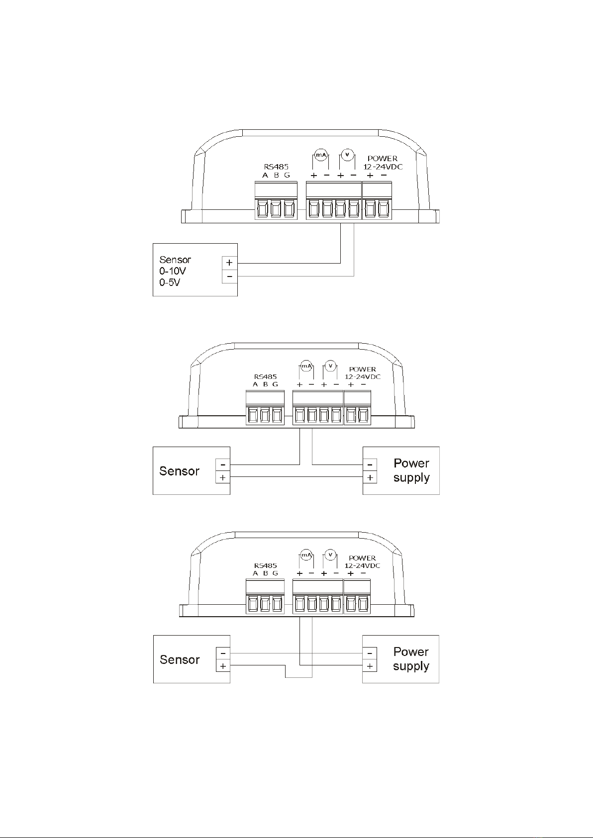
5.4 SENSOR CONNECTING SCHEMATICS.......................................................................................................................10
6 CONFIGURATION OF THE DEVICE.........................................................................................................11
6.1 CHANGING THE DEVICE'S IP ADDRESS BY DISCOVERER APPLICATION.........................................................................11
6.2 CHANGING THE PC'S SUBNET ADDRESS, FOR THE DEVICE CONFIGURATION..................................................................12
6.3 SECURITY SETTINGS AND ADMINISTRATION............................................................................................................14
7 SENSOR SIGNAL CONVERSION FLOW...................................................................................................15
8 THE DEVICE FUNCTIONS...........................................................................................................................17
8.1 THE DEVICE STATUS..........................................................................................................................................17
8.2 CONFIGURATION OF THE ANALOG INPUT................................................................................................................17
8.3 SETTING THE ALARMS........................................................................................................................................18
8.4 SERVICES CONFIGURATION..................................................................................................................................1
8.5 DESTINATION CLIENT (M2M)...........................................................................................................................20
8.6 TCP FRAMES FORMATS (DESTINATION CLIENT)....................................................................................................21
8.7 SNMP CONFIGURATION....................................................................................................................................23
8.8 WINDOWS COMMAND LINE SOFTWARE..................................................................................................................24
8. LINUX CONTROL PROGRAM.................................................................................................................................24
8.10 COMMUNICATION VIA THE MODBUS PROTOCOL...............................................................................................25
8.11 COMMUNICATION VIA THE MQTT INVEO PROTOCOL...........................................................................................28
8.12 COMMUNICATION WITH MODULE USING HTTP....................................................................................................2
8.13 DESCRIPTION OF THE COMMUNICATION PROTOCOL................................................................................................30
COMMUNICATION WITH THE MODULE FROM THE EXTERNAL NETWORK...........................31
10 CHECKING THE IP ADDRESS...................................................................................................................31
11 DHCP................................................................................................................................................................31
12 RESTORING FACTORY DEFAULTS........................................................................................................32
13 FIRMWARE UPDATE..................................................................................................................................32
User manual Nano Analog PoE v2 Page 3 of 32
[B01]

1 Preliminary information
Before starting work with the device, read The User manual and follow the
instructions contained therein!
Description of visual symbols used in t is user manual:
T is symbol is responsible for reviewing t e appropriate place in t e
user instructions, warnings and important information. Failure to
follow warnings could cause injury or damage to t e device
Important information and guidelines
Following t is guidelines makes t e use of t e device easier
Attention: T e screens ots in t is manual can be dissimilar from actual images at
t e time of t e device purc ase. Due to continuous development of t e devices software,
some of t e functions may differ from t ese in t e manual. T e manufacturer claims no
responsibility for any undesirable effects (misunderstanding) caused by c anges of
t e software.
User manual Nano Analog PoE v2 Page 4 of 32
[B01]

2 Application of the device
T e Nano Analog PoE device is used to transmit t e measured current or voltage across
t e LAN. T e measured value is available t roug t e embedded website and via HTTP
GET, Modbus TCP, SNMP and MQTT protocols. An additional RS485 port enables
communication via t e Modbus RTU protocol. T e device can send an exceeded value to
ot er Inveo modules, causing eg remote activation of t e relay.
3 Warranty and liability of the manufacturer
T e manufacturer provides a 2-year warranty on t e device. T e manufacturer also
provides post-warranty service for 10 years from t e date of t e introducing t e device
on t e market. T e warranty covers all defects in material and workmans ip.
T e manufacturer undertakes to comply wit t e contract of guarantee, if t e following
conditions are met:
all repairs, alterations, extensions and device calibrations are performed by t e
manufacturer or aut orized service,
supply network installation meets applicable standards in t is regard,
t e device is operated in accordance wit t e recommendations outlined in t is
manual,
t e device is used as intended.
T e manufacturer assumes no responsibility for consequences resulting from improper
installation, improper use of t e device, not following t is manual and t e repairs of t e
device by individuals wit out permission.
This device doesn’t contain serviceable parts.
User manual Nano Analog PoE v2 Page 5 of 32
[B01]

4 Safety guidelines
T e device as been designed and built using modern electronic components, according
to t e latest trends in t e global electronics. In particular, muc emp asis was placed on
ensuring optimum safety and reliability of control. T e device as a ousing wit a ig -
quality plastic.
4.1 Storage, work and transport conditions
T e device as to be stored in enclosed rooms w ic are free of caustic vapors and
substances and also meet t e requirements:
surrounding temperature from -30°C to +60°C,
umidity from 25 to 90%,
atmosp eric pressure from 700 to 1060 Pa.
T e device working conditions:
surrounding temperature from -10°C to +55°C,
relative umidity from 30% to 75%,
atmosp eric pressure from 700 to 1060 Pa.
Recommended transport conditions:
surrounding temperature from -40°C to +85°C,
relative umidity from 5% to 95%,
atmosp eric pressure from 700 to 1060 Pa.
4.2 Installation and use of the device
The device should be used following the guidelines shown in next part of the
user manual.
4.3 Decommissioning of the device
W en it becomes necessary to recycle t e device (for instance, to decommission t e
device from service), please contact t e manufacturer or its representative, w o are
obliged to respond, appropriately, i.e. collecting t e device from t e user. You can also
ask t e companies involved in recycling of electrical or computer equipment. Under no
circumstances s ould you place t e device along wit ot er waste material.
User manual Nano Analog PoE v2 Page 6 of 32
[B01]

5 Construction of the device
5.1 echnical data
Power supply:
PoE: 33-57V POE IEEE 802.3af
DC: 12-24VDC (screw terminals 3,5mm)
Power consumption: max 1,5W
Input
2 analog inputs
Readout from c osen analog input (voltage or current)
Software configuration
Frequency of measurement: 4Hz
Transducer resolution: 17 bit
Input parameters in current mode:
Measurement range: 0-20mA or 4-20mA
Maximum input current: 25mA
Input impedance: 1R
Measurement error: <0,8%
Input parameters in voltage mode:
Measurement range: 0-5V lub 0-10V
Maximum input voltage: 12V
Input impedance: 60k
Measurement error: <0,5%
Communication:
1 port Et ernet, 10Mbps,
1 port RS485, modbus RTU,
Transmission speed: 1200,2400,4800,9600,19200,38400,57600 bps,
Parity: None, Odd, Even, Mark, Space, 2 Stops.
User manual Nano Analog PoE v2 Page 7 of 32
[B01]

Housing:
IP Code: 30
Dimensions:
5.2 General features
T e general view of t e Nano Analog PoE module is s own below.
T e module supports t e following types of sensors:
- sensors wit voltage output 0-5V
- sensors wit voltage output 0-10V
- sensors wit current output 4-20mA
- sensors wit current output 0-20mA.
T e user can configure t e met od of transformation t e measured value by using t e
function of conversion of t e measured value (mat ematical function), setting t e range
of t e sensor and unit selection.
User manual Nano Analog PoE v2 Page 8 of 32
[B01]

Communication wit t e module is done via LAN and RS485 (Modbus RTU)
T e following communication options are available:
–embedded web server, using a standard internet browser (preferred browsers are
MOZILLA FIREFOX, OPERA, CHROME),
–windows / linux command line programs
–HTTP protocol
–Modbus TCP protocol
–Modbus RTU protocol
–SNMP protocol
–own application via TCP protocol (s ared protocol)
–MQTT to Inveo server protocol
T e module is equipped wit an LED display on w ic t e currently measured value is
displayed.
5.3 Description of the module connectors
T e module is equipped wit t e following connectors:
•LAN – connection of LAN and power PoE IEEE 802.3af,
•RESET – a button to enabling t e DHCP, c ecking t e current IP address and
restoring t e module to t e factory settings,
•mA / V – screw connection for sensor connection (voltage/current),
•RS485 – MODBUS RTU communication connection,
•POWER – power connection. An additional power connection used in t e event of
a PoE power failure. Power supply voltage 12-24VDC.
User manual Nano Analog PoE v2 Page 9 of 32
[B01]

5.4 Sensor connecting schematics
Voltage output sensors (0-10V or 0-5V)
Current output sensor (0- 0mA or 4- 0mA)
User manual Nano Analog PoE v2 Page 10 of 32
[B01]

6 Configuration of the device
T e device w en used for first time needs to be configured.
T ere are two met ods to do so. T e network configuration can be easily c anged by
Inveo “Discoverer” ( ttps://inveo.com.pl/software/) software:
6.1 Changing the device's IP address by Discoverer application.
W en t e “Discoverer” is opened and t e relevant device is found, c oose Interface list
box and click on C ange IP button.
In a new opened dialog box, settings suc
as IP address, MASK, GATEWAY, DNS1/DNS2
and t e Host name can be c anged.
Please save correct settings by c oosing
Change button.
If Remote Config is disabled (enabled by default), it is necessary to configure
t e device by c anging t e computer's subnet (c apter 6.2).
To enable t e remote configuration it is necessary to enter Administration tab
and mark Enable Remote Network Config.
Save t e setup by selecting Save Config button.
User manual Nano Analog PoE v2 Page 11 of 32
[B01]

6.2 Changing the PC's subnet address, for the device configuration
After t e device is connected to a network, a subnet address of a PC w ic is connected
to t e same network as to be c anged.
To do so, go to t e PC's MS Windows network configuration: Start->Control panel
->Network and S aring Center->Network and Internet->Network Connections, c oose
t e related controller and rig t click on „Properties”.
After selecting t is option configuration window will s ow up:
Next c oose "Internet Protocol (TCP/IP)", double click on it and enter following settings:
After saving c anges by clicking OK, open an Internet browser and enter in t e browser's
address line: 192.168.111.15.
efault user name/password: admin/admin00
User manual Nano Analog PoE v2 Page 12 of 32
[B01]
Changing network settings in MS WIN OWS
Illustrative TCP/IP protocol settings

In t e Network tab it is possible to c ange LAN parameters.
To c ange t e network settings, use t e following fields:
•Host Name – NETBIOS name,
•DHCP – c ecking t is box forces use of t e address assigned by t e DHCP server,
•IP Address – t e IP address of t e reader,
•IP Mask – IP subnet mask,
•Gateway – network gateway,
•NS1, NS2 – DNS servers addresses,
•estination IP – t e IP address of t e server or of t e external device
in t e M2M connection (c apter 8.4),
•estination Port – t e listening port of t e server or of t e external device
in t e M2M connection,
•Reset to default – reset t e device to t e factory settings.
After all c anges, select Save.
User manual Nano Analog PoE v2 Page 13 of 32
[B01]

6.3 Security settings and administration
T e Administration settings allow for c anging access password and to enable/disable
particular services in t e device.
The device name
T e device used in a system can be named and identified.
Admin password change
To c ange an administrator password, in Current Password value field write a current
password. Next in appropriate value field New Password write your new password and
confirm it at Re-type Password value field.
Admin Password – an administrator password c ange (login: admin, as access to t e
device all configurations settings)
Current Password – current admin password
New Password – a new admin password
Re-type Password – a new admin password confirmation
User manual Nano Analog PoE v2 Page 14 of 32
[B01]

7 Sensor signal conversion flow
Signal flow from Sensor is s own below.
Current or Voltage input signal (Input) is converted by Analog to Digital Converter (ADC).
Value from ADC is available via A C_Value variable.
Real_Value is measured value given in sensor unit (V or mA). Is t e same value like
measured by multimeter.
T e rangeMin and rangeMax values are sensor measure range. T e rangeMin is
p ysical value of sensor for minimal measured range, i.e. -50ºC for 4mA or 0V. T e
rangeMax is p ysical value of sensor for maximal measured range, i.e. 200ºC for 20mA.
T is parameters are given for calculate real value from sensor and is accesible by
Sensor_Value variable.
Example:
Application use t e t ermometer sensor wit current output 4-20mA and measured
range from -50ºC to 100ºC. T e rangeMin is set to -50 and rangeMax is set to 100.
T e Sensor_Value variable s ow -50 for 4mA and 100 for 20mA. T e remaining values
in t e range will be interpolated.
For better matc ing results for a given application, t e user as a linear function:
Final_Value=a(Sensor_Value+c)*b
It can be used for scale output or add/substract offset to measured value.
Final_Value = Conversion_multiplier * (Sensor_Value + Conversion_pre-offset)
+ Conversion_final-offset
T e Conversion_* variables are real values (wit sign and optional fraction part).
T e use of conversions, for example, allows subtraction from t e measured value of -10,
multiplication by 0.01 (i.e. dividing by 100) to obtain a usable quantity in t e final
application.
T e Final_Value is presented on display LED.
User manual Nano Analog PoE v2 Page 15 of 32
[B01]

Example:
T e Sensor_Value value from t e distance sensor is 2654 cm. T is distance is
overvalued by 10 cm, additionally in t e application it is required t at t e value is
given in inc es. To obtain suc a result, t e coefficients must be set:
Conversion_pre-offset = -10
Conversion_multiplier = 0.394 (1 / 2.54 = 0.394)
Conversion_final-offset = 0
Wit suc coefficients, t e Final_Value value will be corrected for error and
reported in inc es.
T e Scale10000, Scale1000 and Scale100 values are proportional to Real_Value in t e
given range. For example, at t e current input for 4mA Scale10000 = 0, and for 20mA
Scale10000 = 10000.
All resulting values (variables) are available via Modbus TCP, Modbus RTU, HTTP XML and
ot ers.
User manual Nano Analog PoE v2 Page 16 of 32
[B01]

8 The device functions
8.1 he device status
Current data from t e sensor is displayed in t e Home tab.
T e field Sensor Name is t e name of t e sensor edited in t e Input tab.
Alarm State informs about exceeding set t res olds.
8.2 Configuration of the analog input
T e Input tab is to configure t e input type and signal conversion met od.
Before configuring, it is recommended to read t e c apter Sensor signal conversion flow.
Input Name is t e name of t e sensor (not t e device) given by t e user.
T e input type is set in t e field Type. T e options are:
•4-20mA
•0-20mA
•0-5V
•0-10V
User manual Nano Analog PoE v2 Page 17 of 32
[B01]

Range Min and Range Max determine t e range of t e sensor for t e input measuring
range.
T e Conversion… fields set t e conversion parameters of t e measured value
(Sensor_Value) to final value (Final_Value).
T e Unit field allows adding a unit to t e final value of t e measured signal.
8.3 Setting the alarms
T e device can compare t e measured value wit t e t res olds set by t e user.
Detection of value violation is treated as an alarm. T e alarm status is available as virtual
input and for most protocols.
T e alarm can be configured for t e following cases (Alarm mode):
•isabled – t e alarm disabled
•Low – t e alarm is active if t e measured value is smaller t an t e value set in
t e field Alarm Low Value.
•High – t e alarm is active if t e measured value is ig er t an t e value set in
t e field Alarm High Value.
•Low + High – t e alarm is active if t e measured value is ig er t an t e value
in t e field Alarm High Value or lower t an t e value Alarm Low Value.
T e occurrence of an alarm condition is signaled by a flas ing LED display on t e device.
During t e alarm, t e virtual output 1 is activated in t e status.xml resource
ttp://192.168.111.15/status.xml (<on>00000001</on>)
<response>
<prod_name>Nano-AN</prod_name>
<sv>0.9</sv>
<mac>D0:00:00:00:00:00</mac>
<on>00000001</on>
<valFinal>2.49</valFinal>
<unitFinal>m</unitFinal>
<valSensor>2.49</valSensor>
<unitSensor>mA</unitSensor>
<inputType>0</inputType>
<valScale10000>2338</valScale10000>
<valScale1000>233</valScale1000>
<valScale100>23</valScale100>
<iu>7.735</iu>
</response>
If t e SNMP service as been configured, t e device can send TRAP to t e IP address.
User manual Nano Analog PoE v2 Page 18 of 32
[B01]

8.4 Services configuration
Administration tab allows to c oose w ic services are to be available. Selecting t e
c eck box next to t e service name activates t e selected service.
Enable Program Access – a service of access by a computer program (Windows, Linux)
and TCP / IP protocol operating on port 9761,
Enable Modbus TCP – enables Modbus TCP server,
Enable Modbus RTU – enables Modbus RTU (RS485) server,
Enable SNMP – enables SNMP protocol supporting,
Enable estination Client – connecting to a remote ost service (c apter 8.5),
Enable MQTT Inveo – a service t at sends data to t e INVEO MQTT cloud,
Enable Remote Network Config – a service of remote c ange of network settings by
t e INVEO DISCOVERER program,
Enable TFTP Bootloader – enables a bootloader.
Attention:
TFTP Bootloader and Remote Network Config oug t to be disabled during normal
work operation. It s ould be enabled for a firmware update only.
User manual Nano Analog PoE v2 Page 19 of 32
[B01]

8.5 Destination Client (M2M)
Inveo devices as LanTick, Nano Temperature Sensor, Nano Digital Input, Nano Relay
Output or ot ers are able to send information data to the server or to another
module with outputs using t e TCP or UDP protocol. It means t at t is anot er module
can react to activation of c annel or w en alarm occurs (Nano Sensors).
T e message is sent eac time state is c anged and additionally every 5 seconds.
Configuration of devices receiving messages (external devices)
To enable t e service, enter t e Administration tab and select Enable Program
Access and confirm wit t e Save Config button.
Configuration of devices sending alarm status messages
To enable t e service, enter t e Administration tab and select Enable estination
Client and confirm wit t e Save Config button.
In t e Administration tab, fill in t e estination IP and estination Port fields.
T e estination IP field is an IP address of t e external device. T e estination Port
field is a port number of t e external device (9731 by default).
T en, in t e Input tab select t e appropriate output w ic will be enabled in t e external
device or – select type of t e message.
User manual Nano Analog PoE v2 Page 20 of 32
[B01]
Table of contents