VESA Compliance 100x100mm - 600x400mm
Recommended Screen Sizes 32” - 75”
AV Shelf Maximum Load 4.5kg (10lbs)
Screen Load Capacity 45.5kg (100lbs)
To receive large format PDF instructions please email
help@InvisionTechnology.co.uk
Invision GT1200
ScreenStation™
Instruction Manual
Important:
1. Please read instructions fully before installation.
2. Check the box contains all the items in the Parts List.
3. Check your TV screens VESA measurements and
weight before installation (to check your TVs VESA,
measure distance between mounting holes on back of TV).
Lets Get Started!
If you require assistance please contact us at: help@InvisionTechnology.co.uk
WARNING!
Severe personal injury and property damage can result from improper installation, use or assembly. Please read the following warning carefully before
beginning.
• If you do not understand the instructions or have any concerns or questions please contact us or a competent installer.
• Do not install or assemble if the product or hardware is damaged or missing. If you require replacement parts, please contact us at Invision for assistance.
• This product fits most 32”-75” LCD/LED/OLED screens to a maximum weight of 45.5kg (100lbs), AV shelf maximum load of 4.5kg (10lbs).
• Do not use this product for other than the original design purpose.
• This product contains moving parts, please use with caution.
• When installing screen take care not to damage electrical wiring or power source.
• The manufacturer disclaims any liability for the modifications, improper installation or installation over the specified weight range. The manufacturer will not be
liable for any damages arising from the use of, or inability to use the product.
• This product is designed for indoor use only, use of this product outdoors could lead to product failure and severe personal injury.
1
A3 B3 D3
E3
F3
C3
M8x45mm M8x25mm M4x25mmM6x25mm 16x8.2x1.5mm
G1
4X
16x6.2x1.5mm 15x8.2x10mm
M8x26mm M8x70mm M5x12mm 16.5x12.5x2mm M6 M8 M5x10
F1
8X
G3 H3 J3 K3 K3 L3 M3
N3 O3
www.InvisionTechnology.co.uk
v20220620
B1
4X
A1
4X
C1
4X
E1
4X
D1
4X
G2
4X
F2
1X
B2
4X
A2
8X
C2
2X
E2
4X
D2
2X
H2
1X
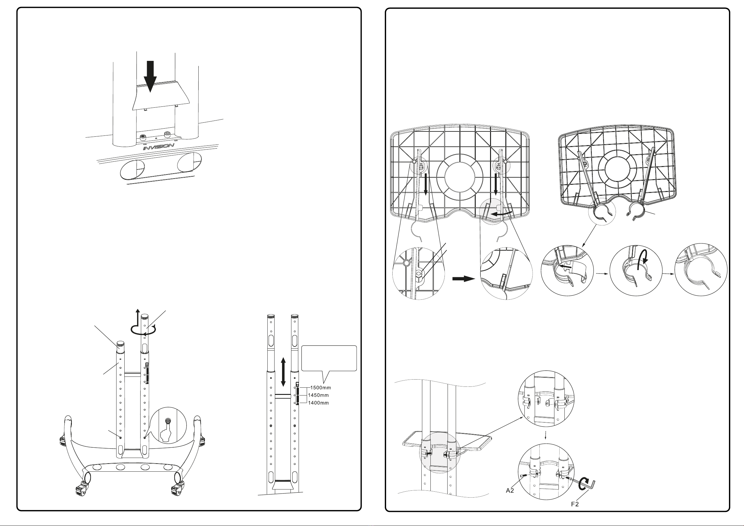
Step 1 - Installing the Castor Wheels to the Base
1. Remove base unit Part ‘A3’ from box, turn over and place on a flat surface so the Invision logo faces the
floor.
2. Lock all the wheels ‘D3’ first by pressing down the brake lever on each wheel - see Diagram ‘A’. Place
‘E2’ washers provided between the base and each wheel then using your hands screw wheels into the base
unit until tight - see Diagram ‘B’.
Step 2 - Fixing Post to Base Installation
1. Turn the base back over onto the wheels and place the posts ‘B3’ into the base, making sure the post
adjustment holes are to the bottom and the cable management access holes are facing to the rear of the base
- see Diagram ‘C’.
2. To secure the posts to the base, loosely fix the bottom two ‘A2’ bolts first then loosely fix the top two ‘A2’
bolts. Check the posts are correctly aligned with the base then tighten up all the bolts using Allen key ‘F2’
provided - see Diagram ‘D’.
Diagram ‘A’ Diagram ‘B’
Diagram ‘C’ Diagram ‘D’
2
Please Note:
Make sure post adjustment holes
are facing the rear of the base and the Invision
logo is situated at the front of the base
Caution:
Only fully tighten each bolt after all 4 have
been partially screwed in, this prevents the
bolts from becoming cross-threaded
E2
F2
A2
D3
A3
B3
English