iO HVAC Controls ZP3-HCMS-ESP Owner's manual

ZP3-HCMS-ESP Installation and Operation Instructions
2 Heat / 2 Cool - Auto Changeover
First Call Priority - Time Share
with Integrated ESP Static Pressure Module
OVERVIEW:
The ZP3-HCMS-ESP is a residential/light
commercial zone control panel that includes
integrated ESP static pressure control logic
designed to eliminate the need for a conventional
bypass damper when used with 3-wire zone
dampers.
SEQUENCE OF OPERATION:
The panel allows a single HVAC unit to have up
to three separate zones. Each zone is controlled
by its own thermostat. When a zone thermostat
calls for heating or cooling, the zones not calling
will have their dampers powered closed, and the
zones calling will have their dampers powered
opened. The heating or cooling equipment will
also be brought on.
As zone dampers open and close, the ZPA-SPS
Static Pressure Sensor continuously monitors
the system static pressure. If the static pressure
goes above the static pressure setpoint, the
panel will send a signal to all selected non-
calling zone dampers to start to open to a point
where the static pressure setpoint is maintained.
The SPS LED will come on with the non-calling
zone LEDs until the static pressure reaches
setpoint. The small amount of air allowed to
bleed into non-calling zones eliminates air noise
and assures proper airflow through the HVAC
system. This also prevents coil freeze up and
high temperature issues.
When all calls are satisfied, all zone dampers will
go to the full open position provided none of the
thermostats are calling for ventilation mode. If
opposite calls take place, the first zone to call for
heating or cooling receives priority. When the first
call is satisfied, the system will changeover and
take care of the opposite call. If zones being
served (heating or cooling) have not been
satisfied within 20 minutes while an opposite call
is taking place, the system will changeover. When
the zone is satisfied or 20 minutes has elapsed,
the system will again changeover if an opposite
call exists. This is referred to as Auto-Changeover
- First Call Priority - Time Share. In the event of a
tie, cooling will receive priority.
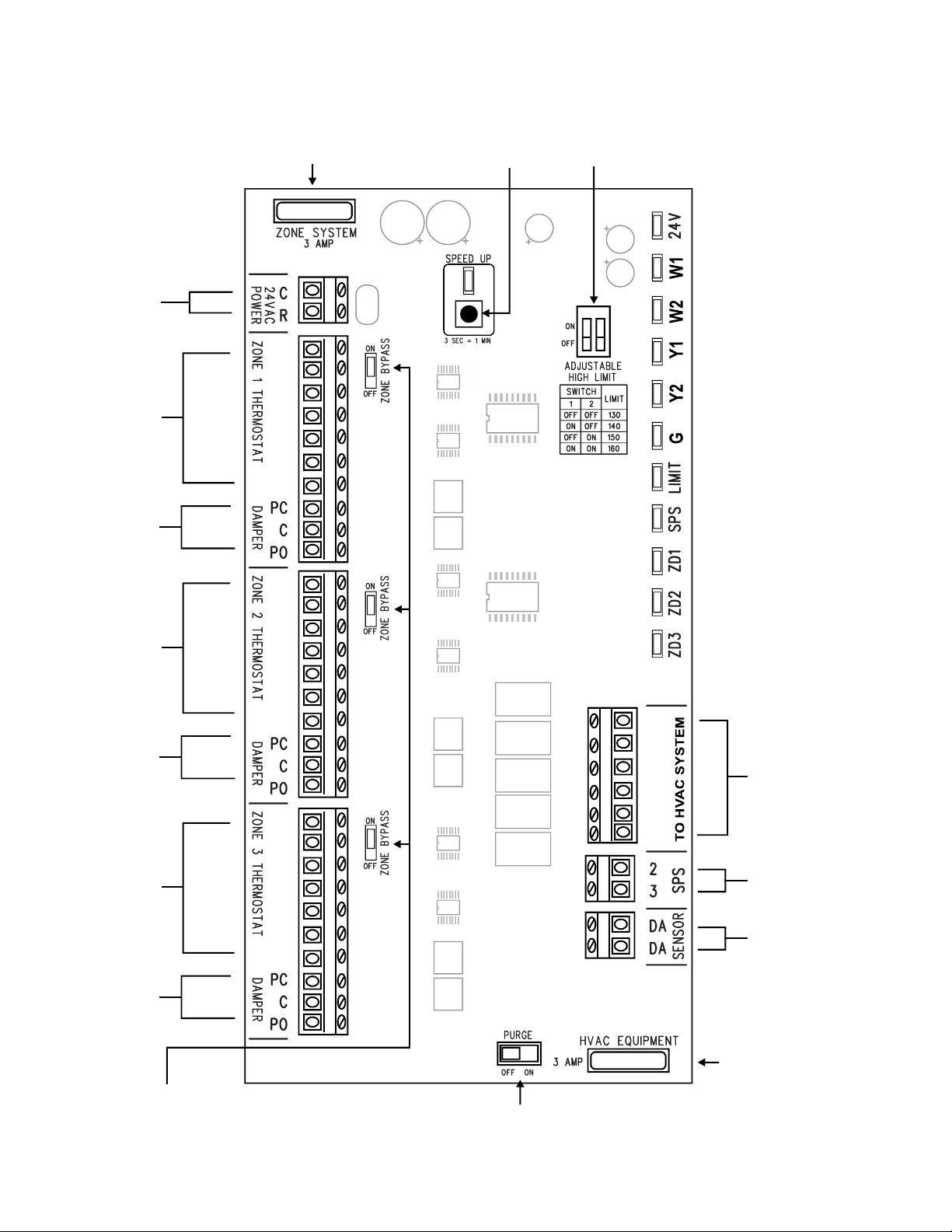
HIGH AND LOW LIMIT PROTECTION:
The ZPA-DTS Discharge Temperature Sensor
should be mounted on the discharge air plenum of
the HVAC unit and wired to the DA terminals on
the panel. The sensor is used for both high
(adjustable) and low (fixed) limit protection. The
high limit setting can be adjusted using the two
slide switches located on the panel. (See switch
location and settings on page 2) Low limit is fixed
at 45° F. When the discharge air temperature rises
above the high limit setting or falls below the low
limit setting, the panel will cycle the equipment off
while the fan continues to run. The LIMIT LED
blinks when high or low limit is reached and a 3
minute time delay is activated to prevent short
cycling of the equipment.
VENTILATION MODE:
Zone ventilation is established by the individual
zone thermostat fan setting. When no calls are
taking place, any thermostat set in the fan AUTO
mode will not receive ventilation air and its zone
damper will be closed. Any zone thermostat set in
the fan ON mode will receive ventilation air and its
zone damper will be opened. Heating or cooling
calls take priority over ventilation mode. The ESP
function will continue to maintain the system static
pressure by modulating open non-calling
ventilation zones as required.
POWER REQUIREMENTS:
The panel is powered by a single 24VAC, 40VA
transformer. Never use the equipment
transformer.
1
3 AMP
3 AMP
.
.
.
.
.
.
.
.
.
R
W1
W2
Y1
Y2
G
C
R
W1
W2
Y1
Y2
G
C
R
W1
W2
Y1
Y2
G
C
R
W1
W2
Y1
Y2
G
302HC
1 2

ZP3-HCMS-ESP Panel Layout
2
3 AMP FUSE PROTECTS
PRINTED CIRCUIT BOARD
3 AMP FUSE PROTECTS
THE RELAY CONTACTS
ZONE 1
THERMOSTAT
ZONE 1 DAMPER
24 VOLTS
PURGE
SWITCH
24 VOLT POWER LED
1ST STAGE HEATING LED
1ST STAGE COMPRESSOR LED
2ND STAGE COMPRESSOR LED
FAN LED
LIMIT LED
ZONE 1 DAMPER LED
ZONE 2 DAMPER LED
ZONE 3 DAMPER LED
ZONE 2
THERMOSTAT
ZONE 2 DAMPER
ZONE 3
THERMOSTAT
ZONE 3 DAMPER
HVAC UNIT
TERMINALS
DISCHARGE
TEMPERATURE
SENSOR
STATIC PRESSURE SENSOR LED
STATIC PRESSURE
SENSOR TERMINALS
SPEED UP
BUTTON
HIGH LIMIT
ADJUSTMENT
SWITCHES
ESP ZONE BYPASS
SELECTOR
PINS
3 AMP
3 AMP
.
.
.
.
.
.
.
.
.
R
W1
W2
Y1
Y2
G
C
R
W1
W2
Y1
Y2
G
C
R
W1
W2
Y1
Y2
G
C
R
W1
W2
Y1
Y2
G
302HC
2ND STAGE HEATING LED
1 2

iO-ZP3-HCMS-ESP TERMINAL DESIGNATIONS
3
TRANSFORMER
24VAC POWER
C (24V COMMON)
R (24V HOT)
W1 (1ST STAGE HEAT)
W2 (2ND STAGE HEAT)
Y1 (1ST STAGE COMPRESSOR)
Y2 (2ND STAGE COMPRESSOR)
G (FAN)
POWER CLOSE
COMMON
POWER OPEN
R (24V HOT)
W1 (1ST STAGE HEAT)
W2 (2ND STAGE HEAT)
Y1 (1ST STAGE COMPRESSOR)
Y2 (2ND STAGE COMPRESSOR)
G (FAN)
WIRE TO ZPA-SPS
STATIC PRESSURE
SENSOR
WIRE TO ZPA-DTS
DISCHARGE
TEMPERATURE SENSOR
R
W1
W2
Y1
Y2
G
C
R
W1
W2
Y1
Y2
G
C
R
W1
W2
Y1
Y2
G
C
R
W1
W2
Y1
Y2
G
302HC
C (24V COMMON)
R (24V HOT)
W1 (1ST STAGE HEAT)
W2 (2ND STAGE HEAT)
Y1 (1ST STAE COMPRESSOR)
Y2 (2ND STAGE COMPRESSOR)
G (FAN)
POWER CLOSE
COMMON
POWER OPEN
C (24V COMMON)
R (24V HOT)
W1 (1ST STAGE HEAT)
W2 (2ND STAGE HEAT)
Y1 (1ST STAE COMPRESSOR)
Y2 (2ND STAGE COMPRESSOR)
G (FAN)
POWER CLOSE
COMMON
POWER OPEN

ZP3-HCMS-ESP LED STATUS DEFINITIONS
4
PURGE SWITCH
PURGE
OFF = NO FAN PURGE
ON = 1 MINUTE FAN PURGE AFTER CALL DROPS OUT
SPEED UP BUTTON
The Speed Up button can be used
to put the internal panel time
delays in speed up mode. When
the button is pushed, the Speed
Up LED will blink. Pushing the
bottom again will reset the time
delays and the LED will turn off or
will automatically reset in 10
minutes.
Speed Up
LED
.
.
.
ESP ZONE BYPASS
SELECTOR PINS
Each zone has an ESP Zone Bypass selector pin. The
panel comes from the factory with all zones set to ON.
By placing a zones selector pin in the OFF position, this
will prevent air from bleeding into the zone when it is
not calling even if the static pressure goes above the
setpoint. This is sometimes useful for basement zones
or zones with small CFM requirements providing other
non-calling zones have the CFM capacity to allow
enough air to bleed without causing air noise without
over heating and cooling.
ADJUSTABLE
HIGH LIMIT
24 VOLT POWER LED
1ST STAGE HEATING LED
1ST STAGE COMPRESSOR LED
2ND STAGE COMPRESSOR LED
FAN LED
LIMIT LED
ZONE 1 DAMPER LED
ZONE 2 DAMPER LED
ZONE 3 DAMPER LED
STATIC PRESSURE SENSOR LED
2ND STAGE HEATING LED
High Limit adjustment switches are located on the
panel. The switches can be set to provide limit
protection below the safety limit on the furnace.
1 2

INSTALLING AND WIRING THE ZP3-HCMS-ESP
MOUNTING THE ENCLOSURE:
Carefully remove the panel from the shipping
carton. Remove the cover and any packing
material. Locate the panel on a flat, non-
condensating, vertical surface near the indoor
unit that will facilitate ease of wiring and service
access. Use appropriate anchors and screws to
secure the panel to the surface.
NOTE:
The panel utilizes home run wiring. Tag each
zone thermostat cable and its associated zone
damper cable to minimize wiring errors.
WIRING ZONE THERMOSTATS:
Use conventional 18-8 thermostat wire. After
removing the outer jacket, strip approximately
1/8” insulation off of each wire. Land each wire to
its designated screw terminal.
WIRING ZONE DAMPERS:
Use conventional 18-3 thermostat wire. After
removing the outer jacket, strip approximately
1/8” insulation off of each wire. Land each wire to
its designated screw terminal.
WIRING TO THE HVAC EQUIPMENT:
Use conventional 18-6 thermostat wire. After
removing the outer jacket, strip approximately
1/8” insulation off of each wire. Land each wire
into its designated screw terminal on the HVAC
UNIT terminals.
Note: Do not wire the equipment common to
the HVAC UNIT terminals on the panel.
INSTALLING AND WIRING THE ZPA-DTS
DISCHARGE TEMPERATURE SENSOR:
Drill a 15/32” hole in the middle of the main
discharge air plenum approximately 18” to 30”
from the heat pump electric strip heater or the
furnace heat exchanger in a fossil fuel
application. Slide the discharge air probe into the
hole and use two self-tapping sheet metal screws
to secure the base to the plenum. Use
conventional 18-2 thermostat wire and wire nuts
to attach the sensor leads. Replace the cover with
the wire nut connections inside. Strip 1/8”
insulation off of each wire at the other end and
land the wires to the screw terminals marked DA
on the panel.
INSTALLING AND WIRING THE ZPA-SPS
STATIC PRESSURE SENSOR:
The ZPA-SPS pressure sensor should be
installed on a flat, surface so that the diaphragm is
in the vertical position. Use the 1/4” x 36” tubing
provided and connect one end to the ( ) high P1+
pressure fitting on the sensor. The other end of the
tubing should be connected to the plastic sensing
probe mounted in the main discharge air plenum
prior to any zone dampers or duct transitions. The
sensing probe is 3-1/8” x 1/4” O.D. Install and
mount the probe with the arrow in the direction of
airflow. The ZPA-SPS is factory set for 0.35” W.C.
but is fully adjustable from 0.08” to 1.20” W.C. The
terminals are not polarity sensitive. Use 18-2
thermostat wire. After removing the outer jacket,
strip approximately 1/8” insulation off of each wire.
Land the wires to the 2 and 3 terminal on the
pressure sensor. Repeat the process on the other
end and land the wires to the screw terminals on
the panel marked SPS 2 and 3.
55
CONTROL MUST BE MOUNTED
IN VERTICAL POSITION
THE 1/4” TUBING SHOULD BE
CONNECTED TO P1+
HIGH PRESSURE FITTING ON THE
PRESSURE SENSOR
AIR HANDLER
TOP VIEW
RETURN
AIR
SUPPLY
AIR
INSTALL
SENSING
PROBE
WITH ARROW
IN DIRECTION
OF AIRFLOW
ZPA-SPS
32
FACTORY SET
0.35” W.G.AT
WIRE TO
SPS 2 & 3
STATIC PRESSURE
SETPOINT DIAL

INSTALLING AND WIRING THE ZP3-HCMS-ESP
WIRING THE TRANSFORMER:
Wire the separate 24 Volt transformer to the
24VAC POWER ‘R’ and ‘C’ terminals. Use
conventional 18-2 thermostat wire. After
removing the outer jacket, strip approximately
1/8” insulation off of each wire. Land each lead to
the 24VAC POWER screw terminals marked C
and R.
TEST, CHECK AND STARTUP:
1. Verify that all component wires have been
connected to the proper terminals and are
secure.
2. Make sure that the selector switches on the
panel are in their proper position.
3. Apply 24 Volt power to the panel.
4. Place all zone thermostats in the OFF mode
with Auto fan.
5. With no calls taking place, the following panel
LEDs should be lit:
24V
LIMIT
ZD1
ZD2
ZD3
6. Visually confirm that all zone dampers are in
the open position.
7. Place zone 1 thermostat in the continuous fan
ON mode and the system blower should come
on. The following panel LEDs should be lit:
24V
G
LIMIT
ZD1
Note: If system static pressure goes above
setpoint, the SPS LED will light along with the
selected non-calling zone LEDs until non-calling
zone dampers modulate to relieve the static
pressure then both LEDs will turn off.
8. Put zone 1 thermostat in Auto fan and repeat
the same steps for zone 2 and zone 3. The only
change in LED status will be ZD2 LED will light
for zone 2 and ZD3 LEDs will light for zone 3.
9. Once the ventilation test is completed, and the
zone thermostat fan modes are set to Auto,
place zone 1 thermostat in the cooling mode and
adjust the setpoint above the space temperature
until it calls for cooling. Keep in mind that the
zone thermostat may have a time delay and that
the panel has a 3 minute short cycle time delay
before allowing the equipment to come on.
6
Once the cooling cycle is energized, the
following panel LEDs should be lit:
24V
Y1
G
LIMIT
ZD1
10. Repeat the same step for zone 2 and zone
3. LED status should be the same with the
exception that ZD2 LED will light for the zone 2
thermostat cooling test and ZD3 LED will light
for the zone 3 thermostat test.
11. The same test can be done for a heating call
from each zone.
12. Once testing is confirmed, place zone
thermostats in their proper mode of operation.

iO-ZP3-HCMS-ESP SPECIFICATIONS:
Enclosure:
Aluminum
Panel Dimensions:
Height: 8.0”
Width: 6.0”
Depth 2.25”
PC Board Mounting:
Individual Snap Track mounted to enclosure base
Operating Temperature Rating:
-40° F to 150° F
Operating Humidity:
5% to 90% RH non-condensing
Wiring:
18-gauge wire for all equipment and component
connections.
Time Delays:
3 minutes off between heating and cooling calls.
3 minutes off on high or low limit
20 minute time share
Purge ON = 1 minute
Thermostats:
Single or multi-stage
Programmable or non-programmable
Auto or manual changeover
Sensors:
ZPA-DTS Discharge Temperature Sensor
NTC Type 3, 10K @ 77° F, +/- 3% @ 77° FΩ
FIELD WIRING TERMINALS:
Zone Thermostats:
C 24Vac (Common)
R 24Vac (Hot)
W1 First Stage Heat
W2 Second Stage Heat
Y1 First Stage Compressor
Y2 Second Stage Compressor
G Fan
HVAC Equipment:
R 24Vac Equipment Hot
W1 First Stage Heat
W2 Second Stage Heat
Y1 First Stage Compressor
Y2 Second Stage Compressor
G Fan
High / Low Limit
DA Land to ZPA-DTS
DA Land to ZPA-DTS
Panel Power:
C 24Vac (Common)
R 24Vac (Hot)
Damper Outputs
PC Power Close
C Common
PO Power Open
Pressure Sensor:
2 Land to ZPA-SPS
3 Land to ZPA-SPS
7
iO-06-1280-060221
Indianapolis, IN 46237
www.iohvaccontrols.com
For Technical Support Call Toll Free: 866-225-5032

Indianapolis, IN 46237
www.iohvaccontrols.com
For Technical Support Call Toll Free: 866-225-5032
SPECIAL ADDENDUM
USING ESP ZONING PANELS WITH GAS FURNACES
HAVING DIRECT SPARK IGNITION (DSI)
DSI functions by creating a rapid series of high-voltage electric
sparks, which means DSI controls generate electromagnetic
interference (EMI) during their trial for ignition. This electronic noise
can sometimes interfere with ESP zoning panels as well as other
nearby electronic components and even with the ignition control itself.
When using an ESP zoning panel with a gas furnace having DSI, we
recommend that the panel be mounted at least ten feet away from the
furnace to reduce any effects of EMI that can cause sporadic cycling
of the relay outputs.
Table of contents
Other iO HVAC Controls Control Panel manuals
Popular Control Panel manuals by other brands

Nederman
Nederman HV Control Panel EX Series Original installation and service manual

Sony
Sony RCP-TX7 Service manual

Metso
Metso LCP9H Series Installation maintenance and operating instructions

SILENTRON
SILENTRON 5529C manual

Tekmar
Tekmar Boiler Control 265 Data brochure

Vertiv
Vertiv Liebert EXL S1 user manual

Altinex
Altinex MULTITASKER MT101-114 user guide

Global Fire Equipment
Global Fire Equipment JUNO NET Configuration and connections

Geotech
Geotech ORS SITEPRO 2000 Installation and operation manual

Honeywell
Honeywell Gamewell-FCI GWF-7075 Installation and operation manual

Observer
Observer TSTAT0201CW installation manual

Oliver IGD
Oliver IGD TOCSIN 700 Installation and user instructions