manuals.online logo
Brands
  1. Home
  2. •
  3. Brands
  4. •
  5. Ioline
  6. •
  7. Industrial Equipment
  8. •
  9. Ioline CrystalPress User manual

Ioline CrystalPress User manual

1
14140 NE 200th St.
Woodinville, WA 98072
1.425.398.8282
www.ioline.com
Replace Sorter Bowl Limit Switch P/N 109799
Procedure P/N 111233 REV 0
Step 1: Tools needed: Needle nose pliers, wire cutters,
11/32” socket wrench, a small (in diameter) phillips
screwdriver and a normal phillips screwdriver.
Step 2: Shown is the limit switch and a black cable tie.
Part number: 109799
Step 3: Turn off the CPII and unplug both the power
cable and the communication cable. Step 4: Turn the CPII on its back and remove all 7
screws. Place the bottom cover to the side.
Step 7: With the 11/32” socket wrench, remove the
center nylon locking nut counter clockwise (appr. 6 1/2
full turns. NOTE: Do not remove the 2 threaded
silver screws. IMPORTANT: When replacing this
screw, you will tighten it appr. 6 1/2 full turns.
Step 5: With the sorter bowl bracket exposed, remove
the 3 nylon locking nuts (counter clockwise) with the
11/32” socket wrench.
Step 8: Shown, the center nylon locking nut removed.
NOTE: The 2 silver screws have not been
removed or loosened.
Step 6: Shown, all 3 locking nylon nuts have been
removed. You can now turn the CPII back on its feet.
2
14140 NE 200th St.
Woodinville, WA 98072
1.425.398.8282
www.ioline.com
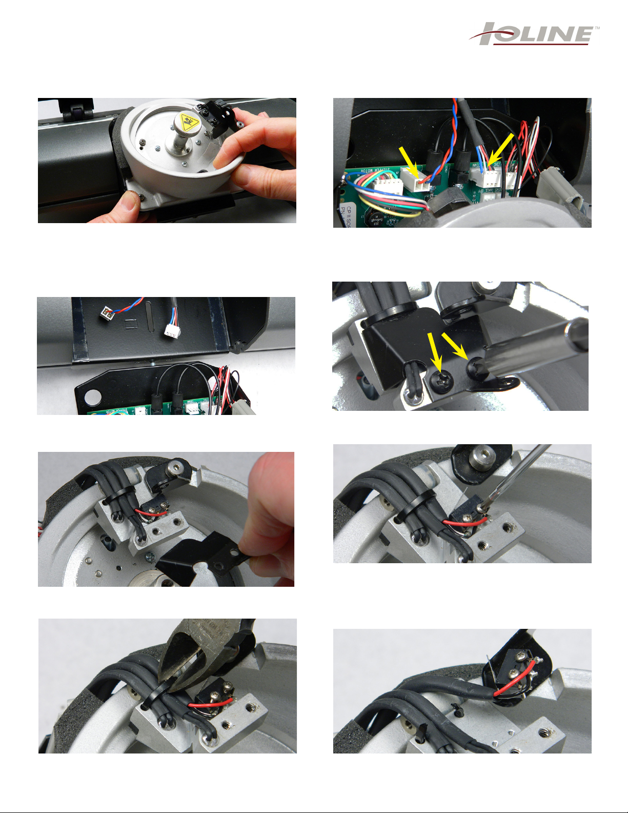
Step 9: Once all 4 locking nuts are removed, you can
remove the bowl from the bracket by pulling out about
1 inch, then lift up about 1 inch. You can now pull the
bowl out until the 2 wires that connect the bowl to the
main board prevent you from pulling further (about 3
inches). See step 10.
Step 10: NOTE: The 2 wires that need to be un-
clipped from the bowl board are shown before
removing the bowl entirely (arrows). NOTE: Pull
the clips straight up to remove from prongs.
Step 11: This shows the 2 wires un-clipped. You can
now move the bowl out to replace the limit switch.
Step 12: With the normal phillips screwdriver, remove
the 2 black screws from the cover (arrows).
Step 13: Once both screws are removed, lift the cover
off and place to the side. You will be placing the cover
back on.
Step 14: With the small phillips screwdriver, unscrew
both of the screws that hold the limit switch to the
jaw. The screws may remain in the old switch. Just pull
them out the rest of the way with a tweezers. NOTE:
You will re-use the screws for the new limit
switch.
Step 15: With the wire cutters, cut the black tie wrap.
IMPORTANT: BE CAREFUL NOT TO CUT THE
BLACK WIRES.
Step 16: The limit switch is now free from the arm.
You now need to turn the bowl towards you to view the
bowl board. Steps 17, 18 and 19.
3
14140 NE 200th St.
Woodinville, WA 98072
1.425.398.8282
www.ioline.com
Step 17: You need to unhook (open) the grey plastic
cable channel (arrow). Step 18: Grab the old limit switch and pull it out from
the cable channel as shown. NOTE: The other 2
wires remain in the cable channel.
Step 19: Shows the limit switch (arrow) already
removed from the board. This is the ‘Arm sensor”. It
has 3 wires Red, Black and White. Discard the old limit
switch.
Step 20: With the needle nose pliers, you need to
remove the tie wrap that you cut. This is slipped
through 2 holes in the arm. This needs to be removed
for the new cable tie wrap.
Step 21: With the new limit switch in hand, it will be
easier to place the 2 small silver screws in the black
plastic portion of the limit switch before screwing onto
the jaw, they will slide in.
Step 22: With the screws in place, align the screws up
with the holes. The holes are threaded and will screw
in the metal arm.
Step 23: IMPORTANT: THE LIMIT SWITCH MUST
GO IN THE WAY AS SHOWN. NOTE: THE ARROW
POINTS TO THE LEVER.
Step 24: You now need to insert the black tie wrap.
You start it on the bottom (side as shown, red arrow).
4
14140 NE 200th St.
Woodinville, WA 98072
1.425.398.8282
www.ioline.com
Step 25: The tie wrap, after inserting in the 1st hole,
wraps over all 3 wires (red arrow), and enters the 2nd
hole (yellow arrow).
Step 26:The tie wrap now is slipped into the locking
end of the tie wrap. The needle nose pliers will assist
in pulling it tight. When complete, cut off the excess.
Step 27: The tie wrap should appear as above. Tight
over the 3 wires. Place back on, the black metal cover
that you see back in step 12.
Step 28: With the arm closed and locked (step 27),
place the 3 wires back in the grey plastic clip as
shown.
Step 29: Snap close the grey plastic clip to keep the
wires in place. Step 30: Re-insert the limit switch (white clip) into
the sorter bowl board. 3 prongs, reads “Arm Sens”.
Shown on how it should appear (arrow).
Step 31: (left photo) Re-insert the 2 white clips,
(Comm) and the (power). You can now place the bowl
back in. The bowl MUST be inserted all the way in. You
can view step 7 & 8, or look at the bowl that you did
not pull out.
Step 32: Once the bowl is inserted correctly, you
should be able to see the threaded stub as in the left
photo. Tighten the nylon locking nut until the bowl will
not move in or out. Turn the CPII on its back and screw
on the 3 nuts and fully tighten, then back off 1/4 turn.
... FINISHED

Other manuals for CrystalPress

4

Other Ioline Industrial Equipment manuals

Ioline CrystalPress User manual

Ioline

Ioline CrystalPress User manual

Ioline CrystalPress-II User manual

Ioline

Ioline CrystalPress-II User manual

Ioline CrystalPress User manual

Ioline

Ioline CrystalPress User manual

Popular Industrial Equipment manuals by other brands

KAKA Industrial Q01-5216 Operation manual

KAKA Industrial

KAKA Industrial Q01-5216 Operation manual

ABB HT844381 Operation manual

ABB

ABB HT844381 Operation manual

ABB HT567830 Operation manual

ABB

ABB HT567830 Operation manual

Airec Cross 30 Installation and maintenance manual

Airec

Airec Cross 30 Installation and maintenance manual

ABB HT610994 Operation manual

ABB

ABB HT610994 Operation manual

DEPURECO RAM OIL T500 Series Use and maintenance manual

DEPURECO

DEPURECO RAM OIL T500 Series Use and maintenance manual

ROCKSOLAR Adventurer User instruction manual

ROCKSOLAR

ROCKSOLAR Adventurer User instruction manual

Allen-Bradley 140MG Series Installation

Allen-Bradley

Allen-Bradley 140MG Series Installation

ROBOTIQ EPick quick start guide

ROBOTIQ

ROBOTIQ EPick quick start guide

Plymovent DRAFTMAX BASIC ULTR A Installation and user manual

Plymovent

Plymovent DRAFTMAX BASIC ULTR A Installation and user manual

Strong GR4 Procedures manual

Strong

Strong GR4 Procedures manual

Borum BOD1906 owner's manual

Borum

Borum BOD1906 owner's manual

SCHUNK DPG-plus Series Assembly and operating manual

SCHUNK

SCHUNK DPG-plus Series Assembly and operating manual

Datacolor 110 user guide

Datacolor

Datacolor 110 user guide

ABB ACS580-01 +C135 Series Original instructions

ABB

ABB ACS580-01 +C135 Series Original instructions

Nabtesco RV RD2 Series Operation manual

Nabtesco

Nabtesco RV RD2 Series Operation manual

Lindab InCapsa Mounting instruction

Lindab

Lindab InCapsa Mounting instruction

M&R Challenger II 12 COLOR manual

M&R

M&R Challenger II 12 COLOR manual

manuals.online logo
manuals.online logoBrands
  • About & Mission
  • Contact us
  • Privacy Policy
  • Terms and Conditions

Copyright 2025 Manuals.Online. All Rights Reserved.