IPC Eagle Ultra Pure Systems Hydro Cart Compact User manual

1. p. 1
Ultra Pure Systems
Hydro Cart Compact
Reverse Osmosis / Deionizing water production machines designed for
water fed pole window cleaning.
OPERATIONS MANUAL
12450 Oliver Avenue South #300 • Burnsville, MN 55123
651.686.5399 • Fax 651.686.5695 • 800.486.2775
www.ipceagle.com

1. p. 2
System Overview
The following information is provided to help you understand how the system
operates.
•Pure water production volume on any Reverse Osmosis system is temperature
dependant.
oColder feed water, i.e. the late fall, winter and early spring will produce a lower
volume (gpm) of pure water.
oWarmer water, i.e. late spring, summer and early fall will produce a higher volume
(gpm) of pure water.
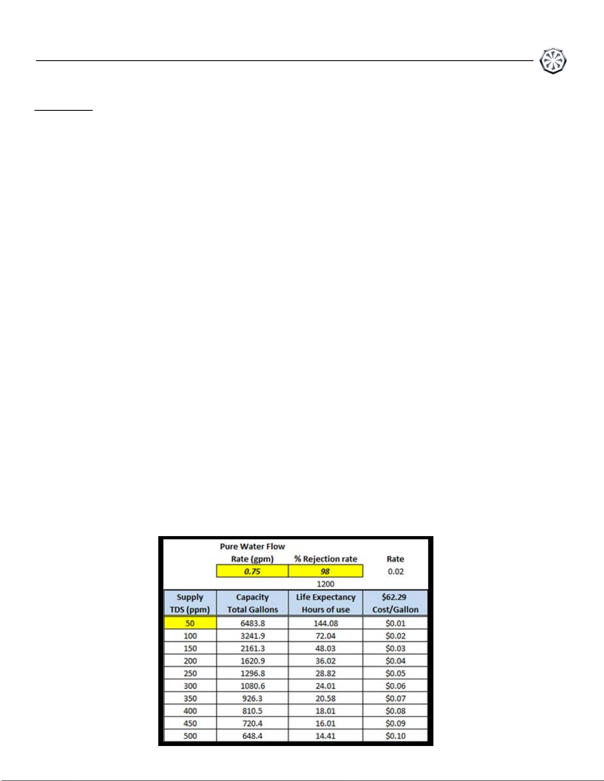
•The reverse osmosis (RO) portion of this system will remove 94% to 98% of the total
dissolved solids (TDS) from the feed water. The amount that is removed depends on
several factors such as water temperature, pressure,water quality, care of membrane and
outside conditions. New membranes may take some time to soak and provide more
efficient removal of dissolved solids.
oExample: if your supply water is 200 parts per million (200 ppm) at a removal rate
of 98% then the RO product water will be 4 ppm. If your supply water is 700 ppm,
then the RO product water will be 14 ppm.
•The RO product water then flows through the deionizing (DI) resin which removes the
balance of the dissolved solids, giving you water at 0 ppm TDS. The DI resin acts like
sponge that absorbs dissolved solids. Once it is full, it has to be replaced.
•The Carbon/Sediment filter removes all solid particles larger than 5 microns in size from
the feed water. In addition, it removes the chlorine from the feed water. Chlorine will
damage the RO membranes and make them ineffective. The carbon block can only hold a
finite amount of chlorine. It must be replaced after 5,000 gallons of feed water have
passed through it or 30 hours.
•Short term and long term storage is an important issue. The system must be protected
from algae and bacteria growth in the pressure vessels caused by stagnant water. The
membranes and DI resin must not be allowed to dry out either. Please see the Storage
section in this manual for proper instructions.
•The unit must be protected from freezing.

1. p. 3
Table of Contents
New Machine Setup Procedure
1. Unpack unit and inspect machine for shipping damage.
2. Take inventory of the following items shipped along with the unit.
•Qty. 1 - RO membrane (installed).
•Qty. 1 - DI resin cartridge (Not installed).
•Qty. 1 - Carbon/Sediment filter cartridge (installed).
•Qty. 1 - Small filter housing wrench.
•Qty. 1 - 50 ft. hose for pure water to pole.
•Qty. 1 - Magic Lube - o-ring lubricant.
•Qty. 1 - TDS meter.
•Qty. 1 - RO Protect Membrane Storage.
•Qty. 1 - Waste water hose.
•Qty. 1 - Axel.
•Qty 2 - Wheels.
•Qty 2 - Axel spacers.
•Qty 2 - Axel push nuts.
•Qty 2 - 5/16" x 2.5" Bolts.
•Qty 2 - 5/16" nuts.
•Qty 4 - 5/16" washers.
•Qty 1 - 22.5" feed hose, black (Top hose).
•Qty 1 - 19" RO discharge hose, black (Bottom hose)
2
13
3 & 4
14
4
15
5
16
5
17
7
8
9
10 & 11
System Analysis
Exploded Parts View Spare
Parts List
Notes
Warranty Policy
Warranty QR Code
11
System Overview New
Machine Setup
Membrane installation
Prefilter installation
DI Resin Cartridge installation
RO Membrane Replacement
HydroCart Compact
Operation Maintenance
RO Membrane Protection
Troubleshooting Procedures
System Performance Evaluation
System Testing 12
Title Page Title Page
6
18

3
4
Fi
t
r
6. C
p
RO
7. C
RO
D
Installation Video
(Scan to watch)
p. 4

Filter Installation
Carbon Sediment cartridge Installation:
•The 5 micron carbon/sediment filter cartridge is
the first filter the feed water goes through. Install it in
the housing on the right side, next to the water
supply hose inlet fitting.
1. Slide the small filter housing wrench up from under
the bottom of the white housing and turn CCW to
loosen. Remove the tool and spin housing
completely off.
2. Lubricate o-ring on housing with Magic Lube
o-ring lubricant.
3. Remove plastic wrapping on new filter cartridge.
Position center hole on shouldered ring on bottom
of housing.
4. Screw housing into base and tighten with small
filter housing wrench. Do not overtighten.
DI resin cartridge Installation:
1. Slide the small filter housing wrench up from under the bottom of the white housing and
turn CCW to loosen. Remove tool and spin housing completely off.
2. Lubricate o-ring on housing with Magic Lube o-ring lubricant.
3. Remove cartridge from the sealed bag and place into housing with seal washer in the
up position and locate the bottom hole on shouldered ring inside the bottom of the
housing.
4. Screw housing into base and tighten with filter housing wrench. Do not overtighten.
The DI filter cartridge is the final filter and removes the rest of the impurity's after the RO.
Install it in the housing on the left side, next to the pure water discharge fitting.
p. 5

RO Membrane Replacement
1. Disconnect the black hose from the top cap of
the RO housing.
2. Remove the clamp holding the top cap on.
3. Remove the top cap by using a screwdriver to
pry the top cap up. There are two notches on
opposite side of each other to pry cap up. Be
careful not to damage.
4. Remove RO membrane by using needle nose
plyers. Grab one of the spokes and pull up.
5. Apply Magic lube to the bottom nipple and top
seal of the RO membrane.
6. Insert membrane into pressure vessel, nipple
goes down and the seal is at the top.
7. Apply Magic lube to the o-rings on the cap and
install on pressure vessel.
8. Install the clamp to hold cap on.
9. Install black hose.
p. 6

HydroCart Compact Operating Instructions
SETUP
1. The machine may be operated standing upright or lying down.
Choose the position that offers the most stability at the job site.
2. Choose a location close to the water supply tap if possible.
Extension garden hoses may be used but must be 5/8 inch inside
diameter or larger to minimize line pressure loss. Additional
extension garden hoses may decrease system volume production
rate.
STARTUP
1. Connect water supply garden hose to feed water inlet connection.
2. Connect the yellow 50 ft hose to pure water outlet connection.
3. Connect wash pole hose to the other end of the 50 foot hose.
4. Connect waste water hose to an area that can accept the water such as
shrubs, trees, grass or drainage that leads to a storm drain. Attach an
extra garden hose if needed to reach the desired area.
Note: The waste water will not harm any plant life. It is just tap water with a higher
total dissolved solids content.
5. Turn on water supply.
6. Test water at the brush using the handheld TDS meter. Water should be less than 10 ppm.
7. Use the ball valve at the pole to adjust desired amount of pure water supplied to brush.
SHUTDOWN
1. Turn supply water off.
2. Let the water drain out of the waste water hose.
3. Connect the end of the waste water hose to the inlet of the Carbon/Sediment
filter for transport and to keep the system from drying out.
p. 7

Maintenance
DAILY
IMPORTANT: After the last use of the day, drain the RO
membrane by letting water flow out of the waste water
hose after removing supply water. This will help flush the
concentrated water from the membrane and increase the
life of the membrane. Reconnect to the intlet to keep
system from drying out.
CARBON/SEDIMENT FILTER
Change every 5000 gallons of feed water run through
the machine, or roughly 30 hours. It is recommended to
replace the carbon filter when the DI resin cartridge is
replaced to assure protection of the RO membrane.
DI RESIN CARTRIDGE
The life expectancy of the DI resin cartridge is based on
the TDS level of the RO water going into it. The RO
will remove up to 98% of the TDS from the feed water.
Example: The feed water supply from a garden hose at your job site has a TDS of 300 ppm. The RO removes
98%, so the water going into the DI resin cartridge will be at 6 ppm. (2% of 300 ppm)
The TDS levels of the feed supply water can vary at each job site due to the water coming from different sources.
The chart below will give you an estimated life based on an average of the supply water.
The supply water temperature will affect the pure water production rate from the RO. This will affect the estimated
reading for DI cartridge replacement as well. Test the water daily, if it goes beyond 10 parts per million change
your DI cartridge.
p. 8

Ultra Pure series Hydro Cart Compact long
term storage instructions
System Preparation:
1. Remove sediment filter and carbon filter, empty water. Reinstall empty
housings.
2. Set green waste water hose on ground to drain system empty. (see fig. A)
3. Remove cap on top of RO pressure vessel.
4. Remove DI resin cartridge. Reassemble empty DI pressure vessel.
5. Allow DI resin cartridge to drain for an hour. Then wrap it securely in
plastic to prevent it from drying out. Store indoors to protect from freezing.
RO Protect Solution preparation and application:
1. Pour entire package of RO Protect
™
into 1 gallon of pure water or distilled
water, mix thoroughly ensuring all powder has been dissolved.
Note: RV antifreeze (propylene glycol) may be used if freeze protection for
system is required. (see fig. B)
2.
Reinstall green hose to the inlet when the solution starts coming out.
3. Slowly pour solution into the top of the RO pressure vessel(s). (see fig. C)
4. Allow time for solution to settle into the membrane, top off as needed,
reinstall all covers and store.
RO Protect™
RO Membrane Protection & Storage Solution
A
MSDS - www.ipceagle.com/MSDS
Set green discharge hose onto the ground
and let waste water flow out of the sysem.
Pour entire package of
RO Protect™ into 1gallon
of pure water or distilled
water, mix thoroughly
ensuring all powder has
been dissolved.
Note: RV antifreeze
(propylene glycol) may be
used if freeze protection
for system is required.
Slowly pour solution into the top of the open
RO pressure vessel(s).
Reinstall green hose to
the inlet when the solution starts coming out.
B
C
p. 9

Troubleshooting Procedures
Condition Solution
Low supply water flow or pressure 1. Eliminate all extension hoses and
connect directly to spigot with a
single hose.
2. Check for blockage or kinks in
hose.
3. Connect to different water source.
4. Clean or replace sediment filter.
High wastewater flow with low
pure water flow good system
pressure
1. Remove DI cartridge and retest
2. Extremely cold water supply
3.
Plugged RO membrane – Replace
RO membrane
High pure water TDS and/or high
pure water flow
1. Damaged membrane –replace
2. Membrane installed upside down
Low System pressure with low
waste water flow
1. Verify supply water conditions
2. Clean or replace carbon sediment
filter.
3. Damaged pump – replace pump
p. 10

Troubleshooting Procedures
System performance evaluation:
In order to properly evaluate and troubleshoot the system, you will need to
perform a complete
set of tests on the unit. These tests will help identify the cause of the problem.
To run these tests, you will need the following items:
•Watch or clock with a sweep second hand.
•3 gallon bucket.
•Volume measurement method. This could be volume graduation marks inside
the bucket or a measuring cup/container.
Flow testing procedure:
•With water running from hose being tested, direct flow into bucket for exactly 1
minute while timing with watch.
•Measure volume of water and record the gallons per minute flow rate.
•If water volume is very low, perform a 2 - minute test and divide flow by 2.
•If water volume is more than your bucket can hold in 1 minute, take a 30 second
flow test and multiply the result by 2.
•Record the results in gpm (gallons per minute).
Use this procedure for all of the required flow tests as listed in the following
System Testing section.
p. 11

1. Set up unit to run as per operation/owners manual. Remove DI cartridge filter before
testing and reattach DI cartridge housing housing.
2. Before connecting the supply water hose to the machine, measure the water flow
from the end of the hose(s).
•Supply water flow __________________ gpm
3. Measure the TDS and temperature of the supply water.
•Supply water TDS __________________ ppm
•Supply water temperature ____________ °C
4. Connect the supply water hose to the machine and turn on the water.
•Supply water pressure _______________ psi
5. Place green waste water hose on the ground to allow water to flow onto the ground
or into a drain. For testing purposes, do not connect a pole hose. Wait for 1 minute
to allow system to stabilize.
6. Measure the water flow from the wastewater hose.
•Wastewater flow ___________________ gpm
7. Measure the water flow from the pure water hose.
•Pure water flow ____________________ gpm
8. Measure the TDS of the pure water.
•Pure water TDS ____________________ ppm
9. Measure the TDS of the wastewater.
•Wastewater TDS ____________________ ppm
10. Turn off machine water and compare test results to normal operation specifications
on page 12.
System Testing
p. 12

System Analysis
The following information of flows and pressures are median values for the system. All system
parameters will vary due to water supply temperature and TDS level. System setup may also affect
the readings. i.e. extension cord size and length, hose lengths and diameters. It is imperative to
connect the machine directly to the water and power source when evaluating performance.
Description Actual Normal
Supply water
______ Flow
TDS ______
______
Temperature
Pressure ______
4 gpm minimum
Check with local water authority
Varies by season and region
40 psi minimum
Specifications
______
______
______
______
System operating pressure
Wastewater flow
Wastewater TDS
Pure water flow
Pure water TDS ______
Identify the parameters that are outside of the normal range and use the information in the
following troubleshooting matrix to correct the situation.
If after performing all tests and working through the matrix you still have operational
issues, please fill out this form completely before contacting IPC Eagle Technical
Service Department. This information is required for proper evaluation of the system.
p. 13
______ 40psi minimum
0.5 gpm
Typically 2x higher than fed water
0.5 gpm minimum
Less than 10 ppm

20
17
17
7
2
10
9
24
23
8
1
10
32
22
22
19
18
14
12
10
15
6
4
5
3
11
21
25
17 25
21
28 27
26
30
31
33 34
33
18
Exploded View
p. 14

Item # Part # Description Qty
1 BD555075 Frame 1
2 BD555086 Handle 1
3 BD555088 Axel 1
4 BD555085 Spacer 2
5 BD555059 Wheel 2
6 BD545150 Axel Push Nut 2
7 BD555076 Tube Cap 3
8 BD411521 Hex Bolt, 5/16 - 18 x2.5" L. 4
9 BD442000 Nut, Nylock 5/16-18 4
10 BD432001 Washer, Flat 5/16 USS 8
11 BD505104 Pre-filter Housing 1
12 BD407001 Screw Plastite, #10 - 14 x1" L 4
13 BD430003 Washer, USS #10 4
14 BD555087 Mounting Bracket, Pre-filter Housing 1
15 BD411515 Hex Bolt 5/16 - 18 x 1.75" 2
17 BD500156 Pushlock 90°, 1/2 npt m x 1/2" 1
18 BD515092 GHF Swivel 1/2npt m 1
19 BD515117 Elbow, Street 45 degree 1
20 BD500157 1/2" Pushlock hose black (cut to length) 2ft each
NS BD515257 Clamp 2
21 BD505136 Pressure Vessel Asm, 4040, Stainless Steel 1
22 BD555077 Clamp, Band, 10" L x 3/4 W, SS 2
23 BD410513 Hex Bolt, SS, 1/4 - 28x 1.5" L 4
24 BD431000 Flat Washer, USS, 1/4, SS 4
25 BD515069 Hex Head, 1/2 npt, Brass 1
26 BD515058 Street Elbow, 90°, 1/2 npt m x 1/2" 1
27 BD515220 Check Valve, 1/2 npt 1
28 BD500104 Flow Regulator Asm, 2 lpm 1
29 BD515258 Hose Barb, 90°m 1/2 npt m x 1/2" 1
30 BD515221 GHM x 1/2 npt 1
Item # Part # Description Qty
1
36 BD545132 Membrane, RO 1
37 BD505108 Carbon Sediment Filter 1
38 BD500117 DI Cartridge, Full 1
40 BD545135 Hose Asm, 1/4 x 50 ft 1
41 BD500150 Interconnect Hose 1
42 Waste Water Hose 1
43 BD515214 Filter Wrench, Small 1
45 BD515153 Magic Lube 1
46 BD545179 TDS Meter 1
47 RO PROTECT RO Protect Membrane Storage, Concentrated Powder 1
Spare Parts List
Items not shown
p. 15

p. 16
Notes

IPC Eagle Warranty Policy
Limited Warranty
IPC Eagle warrants new cleaning equipment against defects in material and workmanship under normal
use and service to the original purchaser as detailed below.
1 year
Subject to the conditions stated below, IPC Eagle warrants all other cleaning equipment components to
be free from defects in materials and workmanship for a 1-year period. Parts replaced or repaired are
warranted for the remainder of the original warranty period. Batteries are pro-rated for one year.
IPC Eagle will furnish and charge for replacement parts, including transportation, to the original owner
through an IPC Eagle authorized service center. If the part is returned within 30 days and is found
defective, the owner will be credited for the cost of the replacement part including shipping and handling.
Wear items exempt from warranty include belts, carbon brushes, power cords, wheels, handle grips,
filters, and screens.
This warranty shall not apply to failures caused by misuse or abuse, improper maintenance as stated in
the operation manuals, use of unauthorized repair parts, repairs by other than an IPC Eagle authorized
service center, and damage in transit.
IPC Eagle disclaims and denies any liability for any direct, indirect, special incidental or consequential
damage which may be suffered as a result of sale, delivery, servicing, use, loss of any product,
downtime, labor, freight, or other charges not expressly included herein.
© Copyright IPC Eagle 2016 Rev F 09/16
12450 Oliver Avenue South #300 • Burnsville, MN 55123
651.686.5399 • Fax 651.686.5695 • 800.486.2775
www.ipceagle.com
p. 17

IPC EAGLE PRODUCT WARRANTY
Thank you for choosing topartner with IPC Eagle. Your IPC Eagle Product has been
thoroughly tested and inspected and iswarranted to be free ofdefects in material
and workmanship for a specific period, depending onthe product purchased. This
warranty does not cover normal wear items such as brushes, belts, filters, power
cords. squeegee blades, wheels and switches. Other items mayapply ornotapply
based on your specific IPC Eagle unit.
If such defects occur, this warranty isvoid if service isattempted by non-
authorized IPC Eagle service providers.
To register your product, goonline to
www.ipcworldwide.com/us/warranty or scan the QRcode below.If preferred,
you can call 651-686-5399 to register by phone.
You will need the machine serial number(s) and date ofpurchase when you
register. For future sales onparts oryour warranty service, please contact the IPC
Eagle distributor you purchased through.
IPC Eagle Corporation 651-686-5399 12450 Oliver Ave South #300 Burnsville, MN 55337
p. 18
Table of contents
Other IPC Eagle Ultrasonic Jewelry Cleaner manuals
Popular Ultrasonic Jewelry Cleaner manuals by other brands

Bowa
Bowa Lotus quick start guide

Powerfix Profi
Powerfix Profi KH 710 operating instructions

Cocraft
Cocraft HA 800 Original instructions

AquaDuna
AquaDuna DUNOS RB 50 operating instructions

Mi-T-M
Mi-T-M AW-7020-8002 Operation instructions

TYROLIT Hydrostress
TYROLIT Hydrostress VCE2500D Series operating instructions