5. Conneting to the Switch
5.1 Using Console Port
Attach a VT100-compatible terminal, or a PC running a terminal emulation program to
the switch. You can use the console cable provided with this package.
To connect a terminal to the console port, complete the following steps :
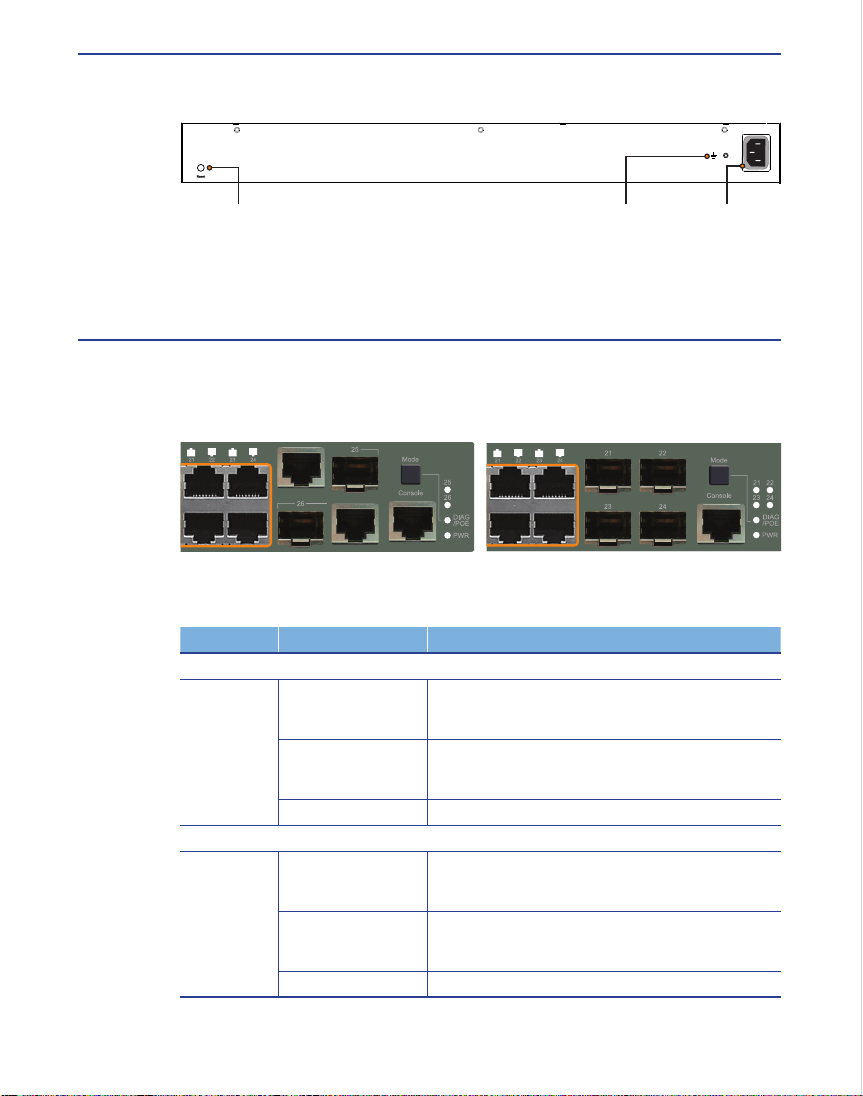
Step 1 : Connect the console cable to the serial port on a terminal, or a PC running
terminal emulation software, and tighten the captive retaining screws on the
DB-9 connector.
Step 2 : Connect the other end of the cable to the RS-232 serial port on the switch.
Step 3 : Make sure the terminal emulation software is set as follows :
• Select the appropriate serial port (COM port 1, or COM port 2, …).
• Select the baud rates to 115200 bps.
• Select the data format to 8 data bits, 1 stop bit, and no parity.
• Set the emulation mode to VT100.
• When using HyperTerminal, select Terminal keys, not Windows keys.
5.2 Accessing the CLI
To access the switch through the console port, perform the following steps :
Step 1 : At the console prompt, enter the user name and password. (The default user
names are “admin” and “guest” with corresponding passwords of “admin”
and “guest”.) When the administrator user name and password is entered,
the CLI displays the “ES-3026#” prompt and enters privileged access mode.
But when the guest user name and password is entered, the CLI displays the
“ES-3026>” prompt and enters normal access mode.
Step 2 : Enter the necessary commands to complete your desired tasks.
Step 3 : When nished, exit the session with the “quit” or “exit” command.
After connecting to the system through the console port, the login screen displays :
User Access Verication
Username: admin
Password:
CLI session with the ES-3026 is opened.
To end the CLI session, enter [Exit]
ES-3026#
5.3 Setting IP Address
You must establish IP address information for the stack to obtain management access
through the network. This can be done in either of the following ways :
• Manual : You have to input the information, including IP address and subnet mask.
If your management station is not in the same IP subnet as the stack’s mas-
ter unit, you will also need to specify the default gateway router.
• Dynamic : The switch can send IPv4 conguration requests to BOOTP or DHCP ad-
dress allocation servers on the network.
To assign an IPv4 address to the switch, complete the following steps :
Step 1 : From the Global Conguration mode prompt, type “interface vlan 1” to access
the interface-conguration mode. Press <Enter>.
Step 2 : Type “ip address ip-address netmask”, where “ip-address” is the switch IP
address and “netmask” is the network mask for the network. Press <Enter>.
Step 3 : Type “exit” to return to the global conguration mode prompt. Press <Enter>.
Step 4 : To set the IP address of the default gateway for the network to which the
switch belongs, type “ip default-gateway gateway”, where “gateway” is the IP
address of the default gateway. Press <Enter>.
5.4 Setting Password
Passwords can consist of up to 8 alphanumeric characters and are case sensitive. To
prevent unauthorized access to the switch, set the passwords as follows :
Step 1 : Open the console interface with the default user name and password “admin”
to access the privileged access mode.
Step 2 : Type “congure” and press <Enter>.
Step 3 : Type “username guest password 0 password”, for the normal access mode,
where “password” is your new password. Press <Enter>.
Step 4 : Type “username admin password 0 password”, for the privileged access
mode, where “password” is your new password. Press <Enter>.
ES-3026(cong)#interface vlan 1
ES-3026(cong-if)#ip address 192.168.1.1 255.255.255.0
ES-3026(cong-if)#exit
ES-3026(cong)#ip default-gateway 192.168.1.254
Username: admin
Password:
CLI session with the ES-3026 is opened.
To end the CLI session, enter [Exit].
ES-3026#congure
ES-3026(cong)#username guest password 0 [password]
ES-3026(cong)#username admin password 0 [password]
ES-3026(cong)#
5.5 Connecting to the Web Interface
Prior to accessing the switch from a web browser, be sure you have rst performed
the following tasks :
Step 1 : Congure the switch with a valid IP address, subnet mask, and default gate-
way using an out-of-band serial connection, BOOTP, or DHCP protocol. (See
“5.3 Setting IP Address”)
Step 2 : Set user name and passwords using a serial connection. Access to the web
agent is controlled by the same user names and passwords as onboard con-
guration program. (See “5.4 Setting Password”)
Step 3 : After you enter a user name and password, you will have access to the sys-
tem conguration program.
When your web browser connects with the switch’s web agent, the home page is
displayed as shown below. The home page displays the Main Menu on the left side of
the screen and System Information on the right side. The Main Menu links are used to
navigate to other menus, and display conguration parameters and statistics.
Quick Installation Guide
iPECS Ethernet Switch
ES-3000/3000G Series
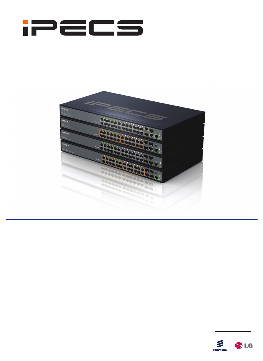
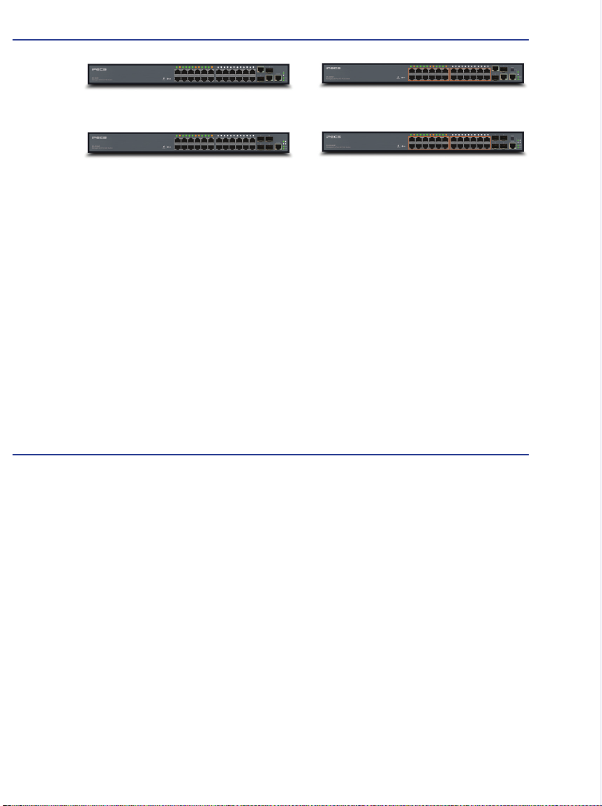
Package Contents
• Managed 26-Port FE Switch (ES-3026) or
Managed 26-Port FE PoE Switch (ES-3026P) or
Managed 24-Port GE Switch (ES-3024G) or
Managed 24-Port GE PoE Switch (ES-3024GP)
• RJ-45 to RS232 Console Cable
• Four Adhesive Foot Pads
• Two Brackets and Eight Screws
• One Ground Screw
• Quick Installation Guide (QIG)
• Manual CD
Note : Power Cord is separately supplied for the product with the sufx of “*.STGDLN”
NOV/2012/ISSUE 2.2
150200000243A R02
Printed in China
Inquire and Technical Support
For further information, please refer to the Ericsson-LG Website at www.ericssonlg.com
Copyright
Information furnished by Ericsson-LG Co., Ltd. (Ericsson-LG) is believed to be accurate and reliable.
However, no responsibility is assumed by Ericsson-LG for its use, nor for any infringements of pat-
ents or other rights of third parties, which may result from its use. No license is granted by implication
or otherwise under any patent or patent rights of Ericsson-LG. Ericsson-LG reserves the right to
change specications at any time without notice.
Copyright Ericsson-LG Co., Ltd. 2011. All rights reserved. Ericsson-LG is a registered trademark.
Other product and company names are trademarks and registered trademarks of their respective-
holders.
iPECS is an Ericsson-LG Brand