manuals.online logo
Brands
  1. Home
  2. •
  3. Brands
  4. •
  5. ipf electronic
  6. •
  7. Security Sensor
  8. •
  9. ipf electronic UT139573 User manual

ipf electronic UT139573 User manual

MANUAL • Subject to alteration! Version: June 2022
ipf electronic gmbh
│
Rosmarter Allee 14 • 58762 Altena • Germany
│
Tel +49 2351 9365-0 • info@ipf-electronic.com •
www.ipf-electronic.com
1
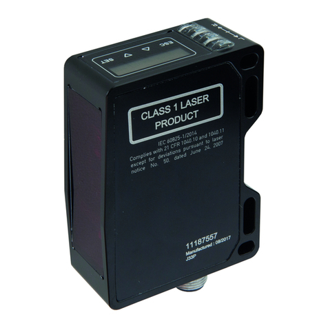
UT139573
Diffuse-reflection sensor
ISetting via teach-in
I3 different teach modes
IPush-pull switching output
IM8-connector
TECHNICAL DATA
Scanning range 40 … 400mm
Operating voltage U
B
18 … 30V DC
Analog output Push-pull, no/nc switchable
Output current (max. load)
150mA
Short-circuit proof
+
Reverse polarity protected
+
Voltage drop
2.0V DC
Switching frequency
10Hz
Current consumption (without load) 40mA
Standard measuring plate
100 x 100mm
Resolution
1mm
Repeatability
0.5mm
Hysteresis
2 … 20mm (adjustable via IO-Link)
Mounting distance (sensor to sensor)
250mm
Setting
Teach-in
Carrier frequency
300kHz
Protection class
III
Insulation dielectric strength
500V
Protection class (EN 60529)
IP 67
Material (housing)
Brass nickel plated
Temperature (operation)
-25 … +70°C
Temperature drift
0.2%/K (uncompensated)
Connection
M8-connector 4-pin
Connection accessories
e.g. VK200375
Connection Dimensional
drawing
IO-Link interface
Normally open contact / normally closed contact switchable
brown
white
Teach-in / lock
black
Push-pull NO / NC switchable
blue
*
*Sound outlet
MANUAL • Subject to alteration! Version: June 2022
ipf electronic gmbh
│
Rosmarter Allee 14 • 58762 Altena • Germany
│
Tel +49 2351 9365-0 • info@ipf-electronic.com •
www.ipf-electronic.com
2
Proper use
Ultrasonic diffuse-reflection sensor are used as part of a higher-level overall system for the contactless detection of objects.
Function
Ultrasonic diffuse-reflection sensors work on the principle of time-of-flight measurement. The device transmits a pulse
sequence, which is then reflected by an object. The device detects the reflected wave and measures the time that has
elapsed between the transmission and reception processes. This time is used to determine the distance between the sensor
and the object. If the results correspond to the specified values, the switching output is set accordingly.
Mounting
The sensor may be mounted in any position. Make sure that it is mounted in a vibration-free and vibration-damping manner.
Also protect the device against mechanical loads such as shocks or impacts.
The transducer surface and the area of the detection lobe must be kept free. Make sure that there are no interfering objects
between the sensor and the target object inside the lobe. Otherwise, it is possible that the interfering object will cause
faulty switching.
Temperature
The speed of sound in air depends on the temperature. Operation outside the specified ambient temperature is not
allowed. A temperature compensation can be switched on via IO-Link.
When temperature compensation is activated, the sensor requires about 15 minutes of warm-up time after a cold start;
only then are the measured values reproducible. Also, avoid positioning two or more ultrasonic sensors opposite each
other.
Transmission angle of the object in diffuse mode
Objects with a smooth surface are scanned reliably up to an angle of
inclination of approx. 10°. The maximum permissible tilting angle
increases for objects with a rough or heavily structured (grained)
surface.
Blind range in touch mode
The range of 0 … 40mm in front of the sensor corresponds to the ultrasonic typical
blind range.
Distance measurements are not possible in the blind range!
The maximum scanning distance 400 mm.
Operation as a reflex barrier can be selected via IO-Link. To do this, set the value 1 to the desired distance from the reference
surface. The selected distance may vary by about 5mm. All objects that interrupt the sound between the sensor and the
reference surface are detected. The blind area may be disregarded in this case.
Sound cone
Plate 100 x 100mm
- - - - - - Round bar Ø 10mm
MANUAL • Subject to alteration! Version: June 2022
ipf electronic gmbh
│
Rosmarter Allee 14 • 58762 Altena • Germany
│
Tel +49 2351 9365-0 • info@ipf-electronic.com •
www.ipf-electronic.com
3
Cleaning
For cleaning a soft cloth moistened with soapy water is recommended.
Commissioning and adjustment
The measuring range is taught-in and the analog output is switched over by connecting the black wire (PIN 2) to the
operating voltage (PIN1).
The teach process is aborted after 20 seconds (Time Out function).
Make sure that the object to be detected is always within the scanning range limits (40 … 400mm).
In normal operation, connect the teach line to 0V to avoid interference.
1. Teach-in of a switching window
1. position the object at the switching limit 1.
2. Connect the white wire to the operating voltage for between 0.1 and 2 seconds. The LED flashes with approx.
1Hz.
3. position the object at the switching limit 2.
4. connect the white wire to the operating voltage for between 0.1 and 2 seconds.
5. the switching output is active at a distance between switching limit 1 and switching limit 2.
2. Teach-in of an object with background suppression (2-point teach)
1. position the object at the desired position.
2. connect the white wire to the operating voltage for between 2 and 4 seconds. The LED flashes with approx.
1Hz.
3. take the object out of the detection lobe so that the sensor is aligned with the background.
4. connect the white wire to the operating voltage for between 0.1 and 2 seconds.
5. the switching threshold is centered between object and background.
3. Automatic teach-in (Auto-Teach)
1. align the sensor with the background.
2. connect the white wire to the operating voltage for between 4 and 6 seconds. The LED flashes with approx.
2Hz.
3. in the next 4 to 8 seconds, guide as many objects as possible past the sensor at the desired distance.
4. the switching threshold is between object and background.
4. Change switching function (no / nc)
1. connect the white wire to the operating voltage for more than 6 seconds.
2. the switching output now works with the inverted function.
5. LED display after each teach process
If the status LED flashes twice, the teach process was successful and the sensor operates with the new values.
If the status LED flashes four times, the teach process has been aborted or the time window of 20 seconds has
been exceeded. The sensor operates with maximum switching distance as a normally open contact.
On the following page the descriptions are shown again graphically.
MANUAL • Subject to alteration! Version: June 2022
ipf electronic gmbh
│
Rosmarter Allee 14 • 58762 Altena • Germany
│
Tel +49 2351 9365-0 • info@ipf-electronic.com •
www.ipf-electronic.com
4
1. Teach-in of a switching window
2. Teach-in of an object with
background suppression (2-
point teach)
3. Automatic teach-in (Auto-
Teach)
4. Change switching function
5. LED display after each teach
process
Note: Resetting to the factory setting is only possible via IO-Link
SAFETY INSTRUCTIONS:
Before commissioning, please make sure that all safety instructions listed in the product documentation, if applicable,
have been observed!
In case of direct impact on personal safety, the use of these products is prohibited.

Other ipf electronic Security Sensor manuals

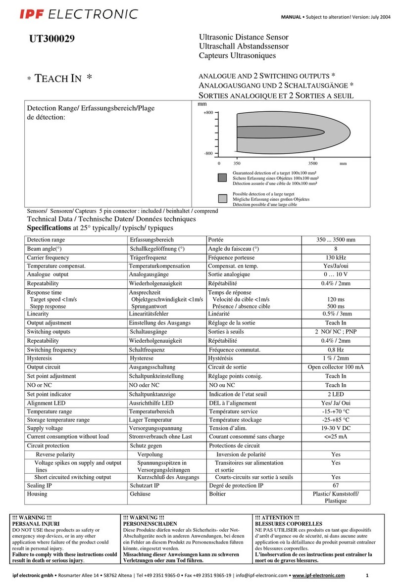
ipf electronic OY36 User guide

ipf electronic

ipf electronic OY36 User guide

ipf electronic UT18002E User manual

ipf electronic

ipf electronic UT18002E User manual

ipf electronic UT300029 User manual

ipf electronic

ipf electronic UT300029 User manual

ipf electronic PY740025 User manual

ipf electronic

ipf electronic PY740025 User manual

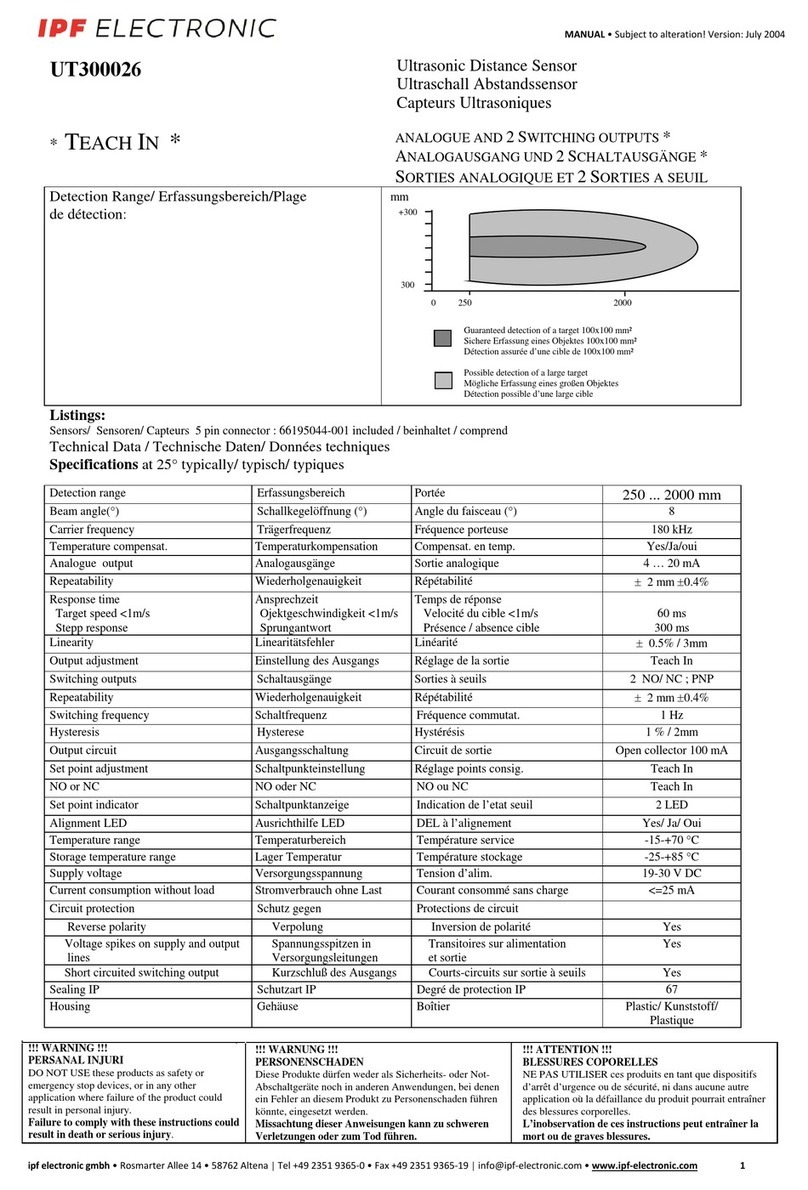
ipf electronic UT300026 User manual

ipf electronic

ipf electronic UT300026 User manual

ipf electronic UT990895 User manual

ipf electronic

ipf electronic UT990895 User manual

ipf electronic UT300024 User manual

ipf electronic

ipf electronic UT300024 User manual

ipf electronic UT300028 User manual

ipf electronic

ipf electronic UT300028 User manual

ipf electronic UY000001 User manual

ipf electronic

ipf electronic UY000001 User manual

ipf electronic PT740020/21 User manual

ipf electronic

ipf electronic PT740020/21 User manual

Popular Security Sensor manuals by other brands

ZyXEL Communications SHD1110 quick start guide

ZyXEL Communications

ZyXEL Communications SHD1110 quick start guide

jablotron JA-187P manual

jablotron

jablotron JA-187P manual

Assa Abloy Yale SR-PC Installation

Assa Abloy

Assa Abloy Yale SR-PC Installation

Samsung ADT SmartThings F-ADT-WTR-1 Setup guide

Samsung

Samsung ADT SmartThings F-ADT-WTR-1 Setup guide

Saxby Lighting PIR MINI instruction manual

Saxby Lighting

Saxby Lighting PIR MINI instruction manual

AJAX FireProtect 2 Jeweller manual

AJAX

AJAX FireProtect 2 Jeweller manual

Jade JD-WD10 manual

Jade

Jade JD-WD10 manual

teko Astra-5121 user guide

teko

teko Astra-5121 user guide

BBC 7.5HK500 Installation & maintenance instructions

BBC

BBC 7.5HK500 Installation & maintenance instructions

hyfire HFI-DPT-05 instructions

hyfire

hyfire HFI-DPT-05 instructions

GORBEL Tether Track TTM-FSC Installation, operation & maintenance manual

GORBEL

GORBEL Tether Track TTM-FSC Installation, operation & maintenance manual

iRay Technology VENU1012V user manual

iRay Technology

iRay Technology VENU1012V user manual

Oxford PRECISION OXD-516-1336M Operator's manual

Oxford PRECISION

Oxford PRECISION OXD-516-1336M Operator's manual

INTER LIGHT IL-CLSR280E manual

INTER LIGHT

INTER LIGHT IL-CLSR280E manual

Omega SA1-RTD instruction sheet

Omega

Omega SA1-RTD instruction sheet

BUCKINGHAM MFG 355B manual

BUCKINGHAM MFG

BUCKINGHAM MFG 355B manual

General NGD7201 user manual

General

General NGD7201 user manual

Phoenix ISL SP-ARC user manual

Phoenix ISL

Phoenix ISL SP-ARC user manual

manuals.online logo
manuals.online logoBrands
  • About & Mission
  • Contact us
  • Privacy Policy
  • Terms and Conditions

Copyright 2025 Manuals.Online. All Rights Reserved.