IPMobileNet IPM4 User manual

I
IP
PS
Se
er
ri
ie
es
s
M
Mo
ob
bi
il
le
e
R
Ra
ad
di
io
o
U
Us
se
er
r
M
Ma
an
nu
ua
al
l
Released: April 8, 2003
IPMN p/n: 516.80495.UM
Revision: A
16842 Von Karman Avenue, Suite 200 Irvine, CA 92606
Voice: (949) 417-4590 Fax: (949) 417-4591
www.ipmobilenetinc.com

2003 IPMobileNet, Inc. Revision & Copyright IPSeries MR User Manual / Rev. A / 08-Apr-03
DOCUMENT REVISION CONTROL
Document Title: IPSeries Mobile Radio User Manual
New Release Version: A
New Release
Date
Previous
Version Action Old
Pages
New
Pages
04/08/03 X6 Release document N/A N/A
COPYRIGHTS STATEMENT
The IPSeries Mobile Radio User Manual is copyrighted to IPMobileNet, Inc.
All rights reserved. This document is confidential and proprietary information of IPMobileNet, Inc. The
distribution or duplication of this document is expressly forbidden without IPMobileNet’s prior written consent.
Disclaimer. While reasonable efforts were made to ensure that the information in this document was complete and
accurate at the time of printing, IPMobileNet, Inc. can assume no responsibility for any inaccuracies. Changes and
corrections to the information within this document may be incorporated in future releases.

TABLE OF CONTENTS
2003 IPMobileNet, Inc. 3 IPSeries MR User Manual / Rev. A / 08-Apr-03
MANUAL COMPONENTS.........................................................................................................................5
Manual Purpose ...........................................................................................................................5
Manual Contents...........................................................................................................................5
Manual Use ...................................................................................................................................6
Audience .......................................................................................................................................6
CHAPTER 1: INTRODUCTION................................................................................................................7
Product Description.......................................................................................................................7
Product Functionality.....................................................................................................................7
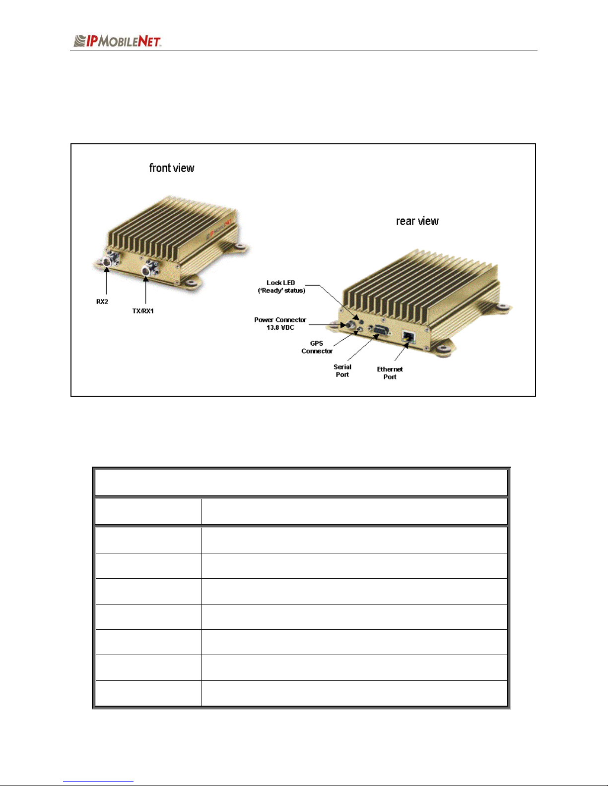
External Features..........................................................................................................................8
Product Specifications...................................................................................................................9
Theory of Operation ....................................................................................................................10
Block Diagram Definitions..............................................................................................10
CHAPTER 2: BASIC NETWORK CONFIGURATIONS.........................................................................12
Basic Network Connection..........................................................................................................12
Network Connection to an Existing LAN .....................................................................................13
Wireless High Speed Digital IP Voice and Data (over the Internet) ...........................................14
CHAPTER 3: SETUP AND CONFIGURATION SCENARIOS...............................................................15
Mobile Radio Setup Scenarios....................................................................................................15
Mobile Radio-to-Mobile Computer Setup.......................................................................15
Mobile Radio-to-VIU-to-Mobile Computer Setup ...........................................................16
CHAPTER 4: PRODUCT INSTALLATION ............................................................................................17
Installation Overview ...................................................................................................................17
Installation Requirements ..............................................................................................17
Installation Instructions................................................................................................................20
Pre-Installation Guidelines .............................................................................................20
Mounting the Mobile Radio ............................................................................................21
Serial Cable Connection and Routing............................................................................22
Ethernet Setup ...............................................................................................................22
Delay Time Installation...................................................................................................22
Carling Switch Installation..............................................................................................24
Mobile Radio Power Supply Installation.........................................................................25
Antenna Configuration ...................................................................................................26
Measuring Return Loss.....................................................................................27
Measuring Voltage Standing Wave Ratio .........................................................28
Measuring Insertion Loss..................................................................................27
Voice Interface Unit Connections...................................................................................28
Post Installation Checklist ..............................................................................................30
Mobile Installation Layout Diagrams ...........................................................................................31
Vehicle Unit Wiring Interconnection Layout ...................................................................31
Mobile Antenna Distance Matrix ....................................................................................31
Diversity Antenna Mobile Installation Detail (Typical Installation) .................................32
Vehicle Unit Wiring Interconnection Layout (with Voice Interface Unit).........................32
Preliminary Testing and Troubleshooting ...................................................................................33
Checklist of Required Materials .....................................................................................33
Base Station Setup for Testing ......................................................................................34
Preliminary Test Procedure and Troubleshooting .........................................................35

TABLE OF CONTENTS
2003 IPMobileNet, Inc. 4 IPSeries MR User Manual / Rev. A / 08-Apr-03
CHAPTER 5: PROGRAMMING INSTRUCTIONS .................................................................................38
Enabling Ethernet for Static IP Address Update in the Mobile Radio.........................................38
Viewing Mobile Radio’s Configuration Data................................................................................40
Changing the Mobile Radio’s IP Address ...................................................................................40
Changing the Mobile Radio’s Parameters ..................................................................................40
Factory Default Save and Restore..............................................................................................43
CHAPTER 6: CUSTOMER SUPPORT ..................................................................................................44
APPENDIX A: Mobile Radio IPMessage Parameters ..........................................................................45
FIGURE LISTING ....................................................................................................................................48
GLOSSARY .............................................................................................................................................49
INDEX ......................................................................................................................................................53

MANUAL COMPONENTS
2003 IPMobileNet, Inc. 5 IPSeries MR User Manual / Rev. A / 08-Apr-03
Manual Purpose
The purpose of the IPSeries IPM Mobile Radio User Manual is to provide IPMobileNet dealers and
customers with the necessary information required to install, operate, and troubleshoot problems with the
mobile radio.
Manual Contents
This user manual contains the following sections:
Chapter 1: Introduction
The Introduction provides a description of the mobile radio as well as a general overview of its
functionality, how it operates, product interfaces, package contents at shipment, and theory of
operation with a block diagram and block definitions.
Chapter 2: Basic Network Configurations
Basic Network Configurations provides a series of network diagrams depicting possible network
configurations.
Chapter 3: Setup and Configuration Scenarios
Setup and Configuration Scenarios provide the diagrams and information required for the two (2)
possible setup methods for the mobile radio.
Chapter 4: Product Installation
Product Installation provides installation diagrams and instructions for installing the mobile radio and
other required components.
Chapter 5: Programming Instructions
Programming Instructions provides programming and setup instructions for setting up the mobile
radio and its interfaces.
Chapter 5: Customer Support
Customer Support provides instructions for ordering parts, documentation support, and reporting
problems.
Appendix A: Mobile Radio IPMessage Parameters
Figure Listing
Glossary
Index

MANUAL COMPONENTS
2003 IPMobileNet, Inc. 6 IPSeries MR User Manual / Rev. A / 08-Apr-03
Manual Use
Special icons appear throughout this manual to emphasize important information related to the chapter in
which the icons are found. The definitions for these icons are listed below.
1It is imperative that the user read this section carefully prior to continuing to the next chapter of
this user manual.
TABLE 1: ICON HELPS
ICON INDICATES DEFINITION
NOTE This icon indicates that a note follows
highlighting or stressing a special point.
%PROCEDURE This icon indicates that the section that
follows contains a procedure.
1CAUTION
This icon indicates that a precautionary
message follows. Carefully read the
message following this icon and proceed with
caution.
#TROUBLESHOOTING This icon indicates that a troubleshooting
strategy follows.
Audience
This user manual is intended for specific use by IPMobileNet, Inc. staff, dealers, and customers. This
user manual is not to be reproduced without expressed written consent of IPMobileNet Management.

CHAPTER 1: INTRODUCTION
2003 IPMobileNet, Inc. 7 IPSeries MR User Manual / Rev. A / 08-Apr-03
Product Description
The content of this manual applies to all frequency ranges of the IPSeries Mobile Radio, unless
otherwise specified. This manual will note key differences when appropriate.
The IPSeries Mobile Radios are intelligent devices designed for the challenging requirements of mobile
data and voice applications. Mounted in vehicles, other intelligent devices may connect to the serial or
Ethernet ports for connectivity back to the Internet Protocol Network Controller (IPNC) and other such
servers. The IPSeries Mobile Radio provides the mobile link to land-based wired networks. The mobile
radio circuit boards are built using surface mount technology (SMT) and through-hole components.
Figure 1: IPSeries Mobile Radio (Front View)
Product Functionality
The mobile radio utilizes a high-performance, 4-level Frequency-Shift Keying (FSK) wireless data modem;
a multi-layered approach to signal reliability, including patented multi-receiver Intelligent Diversity
Reception; data scrambling; data interleaving; Forward Error Correction (FEC); and Viterbi soft-decision
algorithms, providing up to 20 dB improvement in Signal-to-Noise Ratio (SNR) in low signal-to-noise
environments. This assures a very high message success rate even while transferring large blocks of
data at high vehicle speeds. The mobile radio features a low-power consumption, high performance
integrated GPS receiver. Embedding this technology in the mobile radio lowers the cost of acquiring GPS
data from vehicles and ensures optimal performance.
The IPSeries Mobile Radio technology includes IPMobileNet’s Diversity Reception (DR) capability. DR
reduces the effects of fades in multi-path environment. With the use of two (2) antennas mounted at a
calculated distance on the roof of the vehicle (refer to the section in Chapter 4 titled Antenna
Configuration) the Diversity Reception System (DRS) minimizes the effects of fading by intelligently
selecting the receiver with a better signal.
Diversity is most effective when the vehicle is in motion.

CHAPTER 1: INTRODUCTION
2003 IPMobileNet, Inc. 8 IPSeries MR User Manual / Rev. A / 08-Apr-03
External Features
As seen in Figure 2 below, the IPSeries Mobile Radio technology is enclosed in a compact and sturdy
aluminum case.
Figure 2: IPSeries Mobile Radio (External Features)
The mobile radio external features consist of the following components:
TABLE 2: EXTERNAL FEATURES
FEATURE DESCRIPTION
TX/RX1 Transmitter / Receiver 1 antenna connection
RX2 Receiver 2 antenna connection
Power Connector 13.8 VDC mobile radio power connector
Lock LED Unit ‘Ready’ Status Indicator LED (light emitting diode)
GPS GPS antenna (3V) connector
Serial Port RS232 Serial Line Internet Protocol (SLIP) interface port
Ethernet Port 10 Base T Ethernet interface port

CHAPTER 1: INTRODUCTION
2003 IPMobileNet, Inc. 9 IPSeries MR User Manual / Rev. A / 08-Apr-03
Product Specifications
TABLE 3: PRODUCT SPECIFICATIONS
GENERAL SPECIFICATIONS
PARAMETER Model IPM1 Model IPM4 Model IPM8
Frequency range 135 to 175 MHz 400 to 512 MHz 806 to 869 MHz
channel spacing / speed 12.5 kHz / 9600 bps
25.0 kHz / 19200 bps
12.5 kHz / 9600 bps
25.0 kHz / 19200 bps
12.5 kHz / 9600 bps
25.0 kHz / 19200 bps
mode of operation half-duplex, diversity reception half-duplex, diversity reception half-duplex, diversity reception
operating temperature range -30C to +60C (-22F to +140F) -30C to +60C (-22F to +140F) -30C to +60C (-22F to +140F)
power supply voltage 13.8 VDC +/-20% 13.8 VDC +/-20% 13.8 VDC +/-20%
power supply <0.2 amps receive <0.2 amps receive <0.2 amps receive
current consumption 16 amps transmit 13 amps transmit 8 amps transmit
number of channels 256 256 256
intelligent diversity reception dual receiver, diversity reception dual receiver, diversity reception dual receiver, diversity reception
antenna connections Two (2) type “N” jacks
(tx/rx1, rx2)
two (2) type “N” jacks
(tx/rx1, rx2)
two (2) type “N” jacks
(tx/rx1, rx2)
interface connection RS232 serial port connector or
RJ45 Ethernet 10 Base T
RS232 serial port connector or
RJ45 Ethernet 10 Base T
RS232 serial port connector or
RJ45 Ethernet 10 Base T
dimensions (HxWxD / lbs) 2” X 4.5” X 8” / 2.5 lbs 2” X 4.5” X 8” / 2.5 lbs 2” X 4.5” X 8” / 2.5 lbs
Regulatory FCC Part 90 and Part 15 FCC Part 90 and Part 15 FCC Part 90 and Part 15
IPSERIES MOBILE RADIO TRANSMITTER SPECIFICATIONS
PARAMETER Model IPM1 Model IPM4 Model IPM8
frequency stability +/- 1.5 ppm @ operating temp +/- 1.5 ppm @ operating temp +/- 1.0 ppm @ operating temp
emission designator 20K0F1D 20K0F1D 20K0F1D
spurious and harmonic -61 dBc max -59 dBc max -56 dBc max
transmit power 60 watts 40 watts 20 watts
transmit attack time less than 5 ms less than 5 ms less than 5 ms
IPSERIES MOBILE RADIO RECEIVER SPECIFICATIONS
PARAMETER Model IPM1 Model IPM4 Model IPM8
sensitivity (voice) 12.0 dB SINAD@
-119 dB max level
12.0 dB SINAD@
-118 dB max level
12.0 dB SINAD@
-118 dB max level
distortion less than 3% @ 1.0 kHz less than 3% @ 1.0 kHz less than 3% @ 1.0 kHz
spurious response 85 dBm minimum 85 dBm minimum 85 dBm minimum
intermodulation distortion 75 dB minimum 75 dB minimum 75 dB minimum
GPS RECEIVER SPECIFICATIONS
general L1 frequency, C/A code (SPS), 8-channel continuous tracking receiver, 32 correlators
protocols TSIP, TAIP, and NMEA 0183

CHAPTER 1: INTRODUCTION
2003 IPMobileNet, Inc. 10 IPSeries MR User Manual / Rev. A / 08-Apr-03
Theory of Operation
Figure 3: General Block Diagram
Block Diagram Definitions
For increased data security, the modem supports the Federal Government developed Digital
Encryption Standard (DES) data encryption and decryption protocols. This capability requires
installation of third party, Internet Protocol (IP) compliant DES encryption and decryption
software on the system.
The IPSeries Mobile Radio is comprised of two (2) sections, the digital section and the RF (radio
frequency) section.
The digital circuit board contains the following sections:
Input/Output Circuitry associated with the following data connectors:
RS232 Serial Port DB9 Data Connector
RJ45 Ethernet 10 Base T Interface Connection
For further details on the Ethernet Controller refer to the Crystal
LANEthernet Controller Product Bulletin (CS8900A-
EthernetCtrlr.pdf) available on the Product Documentation CD.
Microcontroller Manages the operation of the mobile radio, the modem, and determines
which receiver provides a better signal from a given transmission. Also
provides transmit time-out protection in the event a fault causes the mobile
radio to halt in the transmit mode.
Modem Converts serial data into an analog audio waveform for transmission and
analog audio from the receiver to serial data. Within a single chip it
provides forward error detection and correction, bit interleaving for more
robust data communications, and third generation collision detection and
correction capabilities.

CHAPTER 1: INTRODUCTION
2003 IPMobileNet, Inc. 11 IPSeries MR User Manual / Rev. A / 08-Apr-03
Power Supply The power supply creates the various voltages required by the digital
portion of the mobile radio.
The RF circuit board contains the following sections:
Transmit Processing Circuitry that amplifies the analog audio signal from the modem and uses it
to modulate the voltage-controlled oscillator (VCO) and reference oscillator
in the injection synthesizer section. Modulating the VCO and reference
oscillator simultaneously results in a higher quality FM signal.
Injection Synthesizer Provides programmable, ultra stable signals for the mobile radio.
Synthesizer incorporates phase lock loop technology used for both
receiving and transmitting.
Injection In the receive mode, the synthesizer provides a local oscillator signal of 45
MHz above or below the selected receive channel frequency.
Transmitter Consists of an exciter and power amplifier module. The transmitter covers
the various frequency bands in segments. A different power amplifier
module is required for each segment. The transmitter circuitry includes a
T/R switch switching the antenna between transmitter and receiver 1
(TX/RX1).
Receiver 1/Receiver 2 Required to support the mobile DRS; two (2) discrete receivers are tuned
to the same channel and use two (2) antennas.
The receivers are double-conversion superheterodyne with a first
Intermediate Frequency (IF) of 45 MHz and a second IF frequency of 455
KHz. Each receiver consists of bandpass filters, an RF amplifier, a MMIC
mixer, crystal filters, and a one-chip IF system. The injection synthesizer
provides the first local oscillator signal. Outputs from each receiver include
RSSI and analog audio for the baseband routing circuitry and modem.
For further details on the integrated GPS unit, refer to the Lassen GPS Unit Specification
(Lassen-GPSUnitSpec.pdf) available on the Product Documentation CD.

CHAPTER 2: BASIC NETWORK CONFIGURATIONS
2003 IPMobileNet, Inc. 12 IPSeries MR User Manual / Rev. A / 08-Apr-03
Basic Network Configurations
This section provides basic network connection samples to help the user better understand some of the
possibilities in setting up their respective systems.
Basic Network Connection
Figure 4 depicts a basic network connection for a network inclusive of one (1) Internet Protocol Network
Controller (IPNC) and a range of base stations, mobile radios, VIUs (voice interface units), mobile
computers, and additional components that can interface with the system.
Figure 4: Basic Network Connection

CHAPTER 2: BASIC NETWORK CONFIGURATIONS
2003 IPMobileNet, Inc. 13 IPSeries MR User Manual / Rev. A / 08-Apr-03
Network Connection to an Existing LAN
Figure 5 depicts network connection to an existing LAN (local area network) inclusive of one (1) IPNC,
one (1) base station, and a range of mobile radios, VIUs, mobile computers, and additional components
that can interface with the system. This diagram also shows a LAN VIU as well as Terminal Server VIU.
Figure 5: Network Connection to an Existing LAN

CHAPTER 2: BASIC NETWORK CONFIGURATIONS
2003 IPMobileNet, Inc. 14 IPSeries MR User Manual / Rev. A / 08-Apr-03
Wireless High Speed Digital IP Voice and Data (over the Internet)
Figure 6 depicts a variety of wireless data and voice networks on different frequencies.
Figure 6: Wireless High Speed Digital IP Voice & Data (over the Internet)

CHAPTER 3: SETUP AND CONFIGURATION SCENARIOS
2003 IPMobileNet, Inc. 15 IPSeries MR User Manual / Rev. A / 08-Apr-03
Mobile Radio Setup Scenarios
The following describes the two (2) methods of setting up a mobile radio in a vehicle:
Mobile Radio-to-Mobile Computer
Mobile Radio-to-VIU-to-Mobile Computer
Mobile Radio-to-Mobile Computer Setup
Figure 7: Mobile Radio-to-Mobile Computer Setup
To setup a mobile radio-to-mobile computer configuration, additional components are required, as listed
in Table 4:
TABLE 4: MOBILE RADIO-TO-MOBLE COMPUTER COMPONENTS REQUIRED FOR
INSTALLATION
QTY DESCRIPTION
1 IPM Mobile Radio
1 Mobile Computer
1 20-foot serial cable (DB9F – DB9M)
1 Mobile Radio SLIP Port Driver Installation Diskette
If using the mobile radio’s Ethernet feature an Ethernet crossover cable is required to replace 20-
foot serial cable.
To configure the mobile radio and computer for this type of setup, follow the instructions on pages
2 through 17 in the Mobile Computer Setup for Communication with the Mobile Radio
Installation Guide (IPMN p/n: 516.80310.IG) available on the Product Documentation CD.

CHAPTER 3: SETUP AND CONFIGURATION SCENARIOS
2003 IPMobileNet, Inc. 16 IPSeries MR User Manual / Rev. A / 08-Apr-03
Mobile Radio-to-VIU-to-Mobile Computer Setup
Figure 8: Mobile Radio-to-VIU-to-Mobile Computer Setup
To setup a mobile radio-to-VIU-to-mobile computer configuration, additional components are required, as
listed in Table 5:
TABLE 5: MOBILE RADIO-TO-VIU-TO-MOBLE COMPUTER COMPONENTS
REQUIRED FOR INSTALLATION
QTY DESCRIPTION
1 IPM Mobile Radio
1 Mobile Computer
1 Voice Interface Unit (VIU)
1 20-foot serial cable (DB9F – DB9M)
1 10-foot serial cable (DB9F – DB9M)
1 Mobile Radio SLIP Port Driver Installation Diskette
To configure the mobile radio, the voice interface unit, and the mobile computer for this type of
setup, follow the instructions on pages 18 and 19 in the Mobile Computer Setup for
Communication with the Mobile Radio Installation Guide (IPMN p/n: 516.80310.IG) available on
the Product Documentation CD.

CHAPTER 4: PRODUCT INSTALLATION
2003 IPMobileNet, Inc. 17 IPSeries MR User Manual / Rev. A / 08-Apr-03
Installation Overview
This chapter provides the basic steps involved in the installation process of an IPSeries Mobile Radio.
This chapter includes wire routing and connections between the mobile radio, other components, and the
vehicle’s power.
1To prevent personal injury and vehicle damage, exercise extreme caution throughout the
installation process and follow the reminders listed below.
Follow safety precautions for handling wiring, tools, and a vehicle’s engine.
Handle the vehicle’s battery with extreme caution to avoid burns.
Do not alter the components listed in the Installation Requirements section below, unless
substitutions are noted within this chapter.
Once the antennas are installed, as directed within this user manual, all persons must
maintain a distance of no less than 39 inches from the antennas.
Installation Requirements
Table 6 lists the documents required to successfully install the mobile radio and connect to the various
components within the vehicle:
TABLE 6: DOCUMENTS REQUIRED FOR MOBILE RADIO INSTALLATION
DESCRIPTION PART NUMBER
The following documents are available on the Product Documentation CD
enclosed in the shipment with the mobile radio: 480.0001.001
IPSeries Mobile Radio User Manual 516.80495.UM
Installation Guide for Mobile Computer Setup for Communication with
the Mobile Radio 516.80310.IG
Confirming Mobile Radio Receiver Sensitivity TN01-0027

CHAPTER 4: PRODUCT INSTALLATION
2003 IPMobileNet, Inc. 18 IPSeries MR User Manual / Rev. A / 08-Apr-03
Table 7 lists the components required to perform a successful mobile radio installation and are available
for purchase through IPMobileNet, Inc.
TABLE 7: MOBILE INSTALLATION ACCESSORIES KIT
QTY DESCRIPTION PART NUMBER
4 Screws, Self Tapping #10 X 5/8 37040010-10
1 EMI Filter 127-0020-002
1 Timer, 2 hours 150-0127-004
1 Relay 128-0117-001
1 Relay Socket 128-0116-001
2 Butt Connectors #8 AWG 120-0256-001
1 Terminal, Ring #8 AWG, #10 Screw Insulated 120-0127-001
4 Terminal, Ring #18-22 AWG, #10 Screws Insulated 120-0250-004
4 Terminal, Ring #10-12 AWG, #10 Screws Insulated 120-0250-005
4 Terminal, Disconnect #14-16 F 120-0244-002
18 Terminal, Disconnect #10-12 F 120-0244-003
2 Disconnect Tab, Quad Male 200-1377-001
1 Wire, 12 AWG Black, order 5 ft. 156-0242-001
1 Wire, 12 AWG Red, order 44 ft. 156-0242-003
1 Fuse, 15 AMPS ATO 122-0042-003
2 Fuse, 30 AMPS ATO 122-0042-001
3 Fuse Holder, 12 AWG 120-0253-001
1 Switch, Toggle DPST 144-0136-001
1 Diagram, Mobile Installation without VIU (see page 31) 502-80259
1 Diagram, Mobile Installation with VIU (see page 32) 502-80260

CHAPTER 4: PRODUCT INSTALLATION
2003 IPMobileNet, Inc. 19 IPSeries MR User Manual / Rev. A / 08-Apr-03
Table 8 lists the auxiliary equipment required to complete the installation process.
TABLE 8: AUXILIARY EQUIPMENT
QTY DESCRIPTION PART NUMBER
1 Serial Cable (DB9MF), 20 ft. 156-0245-020
1 Wire, 8 (133/29) AWG VW-1 Red, by foot, order 19.5 ft. 156-0243-003
1 Wire, 8 (133/29) AWG VW-1 Black, by foot, order 19.5 ft. 156-0243-001
2 RG58U Cable and Mount, VHF, 17 ft. (incl ¾” Brass Mount and N Male Crimp) 102-0200-001
2 RG8X Cable and Mount, UHF & 800 MHz, 17 ft. (incl ¾“ Brass Mount & N Male Crimp) 102-0200-002
2 Antenna, ¼ Wave, 136-144 MHz 102-0204-001
2 Antenna, ¼ Wave, 144-152 MHz 102-0204-002
2 Antenna, ¼ Wave, 152-162 MHz 102-0204-003
2 Antenna, ¼ Wave, 162-174 MHz 102-0204-004
2 Antenna, Radome Type, 410-430 MHz, 3dB Gain (requires 1 MB8XN for ea antenna) 102-0206-001
2 Antenna, Radome Type, 430-450 MHz, 3dB Gain (requires 1 MB8XN for ea antenna) 102-0206-002
2 Antenna, Radome Type, 450-470 MHz, 3dB Gain (requires 1 MB8XN for ea antenna) 102-0206-003
2 Antenna, Radome Type, 470-490 MHz, 3dB Gain (requires 1 MB8XN for ea antenna) 102-0206-004
2 Antenna, Radome type, 806-866 MHz, 3dB Gain (requires 1 MB8XN for ea antenna) 102-0207-001
2 Antenna, Radome Type 821-896 MHz, 3dB Gain (requires 1 MB8XN for ea antenna) 102-0207-002
2 Antenna, 5/8 Wave, 406-430 MHz, 3dB Gain (requires 1 MB8XN for ea antenna) 102-0199-003
2 Antenna, 5/8 Wave, 430-450 MHz, 3dB Gain (requires 1 MB8XN for ea antenna) 102-0199-004
2 Antenna, 5/8 Wave, 450-470 MHz, 3dB Gain (requires 1 MB8XN for ea antenna) 102-0199-005
2 Antenna, 5/8 Wave, 470-490 MHz, 3dB Gain (requires 1 MB8XN for ea antenna) 102-0199-002
2 Antenna, 5/8 Wave 490-512 MHz, 3dB Gain (requires 1 MB8XN for ea antenna) 102-0199-006
2 Antenna, 5/8 Wave, 806-866 MHz, 3dB Gain (requires 1 MB8XN for ea antenna) 102-0199-001
2 Antenna, ¼ Wave, 406-430 MHz, Unity Gain (requires 1 MB8XN for ea antenna) 102-0204-005
2 Antenna, ¼ Wave, 430-450 MHz, Unity Gain (requires 1 MB8XN for ea antenna) 102-0204-006
2 Antenna, ¼ Wave, 450-470 MHz, Unity Gain (requires 1 MB8XN for ea antenna) 102-0204-007
2 Antenna ¼ Wave, 470-490 MHz, Unity Gain (requires 1 MB8XN for ea antenna) 102-0204-008
2 Antenna, ¼ Wave, 490-512 MHz, Unity Gain (requires 1 MB8XN for ea antenna) 102-0204-009
2 Antenna, ¼ Wave, 806-896 MHz, Unity Gain (requires 1 MB8XN for ea antenna) 102-0204-010

CHAPTER 4: PRODUCT INSTALLATION
2003 IPMobileNet, Inc. 20 IPSeries MR User Manual / Rev. A / 08-Apr-03
Installation Instructions
Pre-Installation Guidelines
Prior to installing new equipment, perform the following steps:
11. Remove existing equipment and all related components to include stock clips on radio
wiring harness and antenna.
2. As shown in Figure 9 below, mounting of the mobile radio, delay timer, relay, and EMI
filter will take place in the trunk compartment, unless installing in a vehicle without a trunk
(refer to page 31 for the full drawing).
Figure 9: Trunk Compartment Installation
Removal of seats, rubber mats, and other obstructions, from inside the driver compartment, may
be necessary to facilitate routing of wires to the engine and trunk compartments.
3. To ensure appropriate cable and wire routing, exercise the following precautions:
Route cables away from sharp edges that can penetrate cable insulation and damage
wires.
Protect wires with silicone rubber grommets when routing through the engine
compartment firewall or through other holes with sharp edges.
Use high-quality electrical tape when covering exposed wires in the engine
compartment.
Avoid routing cables through areas exposed to extreme heat, such as the exhaust
system.
This manual suits for next models
2
Table of contents
Other IPMobileNet Radio manuals

IPMobileNet
IPMobileNet M64700G25 User manual

IPMobileNet
IPMobileNet IP Series User manual

IPMobileNet
IPMobileNet M1617-12 User manual

IPMobileNet
IPMobileNet M64800D25 User manual

IPMobileNet
IPMobileNet M64780D25 User manual

IPMobileNet
IPMobileNet IP Series User manual

IPMobileNet
IPMobileNet IPM8 User manual

IPMobileNet
IPMobileNet F32700N25 User manual