IPMobileNet M64700G25 User manual

I
IP
PS
Se
er
ri
ie
es
s
M
M6
64
47
70
00
0G
G2
25
5
H
Hi
ig
gh
h
S
Sp
pe
ee
ed
d
M
Mo
ob
bi
il
le
e
R
Ra
ad
di
io
o
P
Pr
ro
od
du
uc
ct
t
O
Ow
wn
ne
er
r’
’s
s
M
Ma
an
nu
ua
al
l
Date Released: March 30, 2005
Document #: 516.80528.POM
Revision: B
Copyright 2005 IPMobileNet, Inc.
16842 Von Karman Avenue, Suite 200 Irvine, CA 92606
Voice: (949) 417-4590 Fax: (949) 417-4591

M64700G25-FCCRpt.doc Page ii
The term “IC”: before the radio certification number only signifies that Industry of Canada
technical specifications were met.
Operation is subject to the following two (2) conditions: (1) this devise may not cause
interference, and (2) this device must accept any interference, including interference that may
cause undesired operation of this device.
The following U.S. Patents apply to this product:
U.S. Patent numbers 5,640,695,6,018,647,6,243,393
Information contained in this document is subject to change without notice.
All rights reserved. Reproductions, adaptations, or translation without prior written permission is
prohibited, except as allowed under copyright laws.

TABLE OF CONTENTS
M64700G25-FCCRpt.doc Page 2
SECTION 1: OVERVIEW..........................................................................................................................3
Product Description....................................................................................................................3
M64700G25 Mobile Radio Section Descriptions......................................................................3
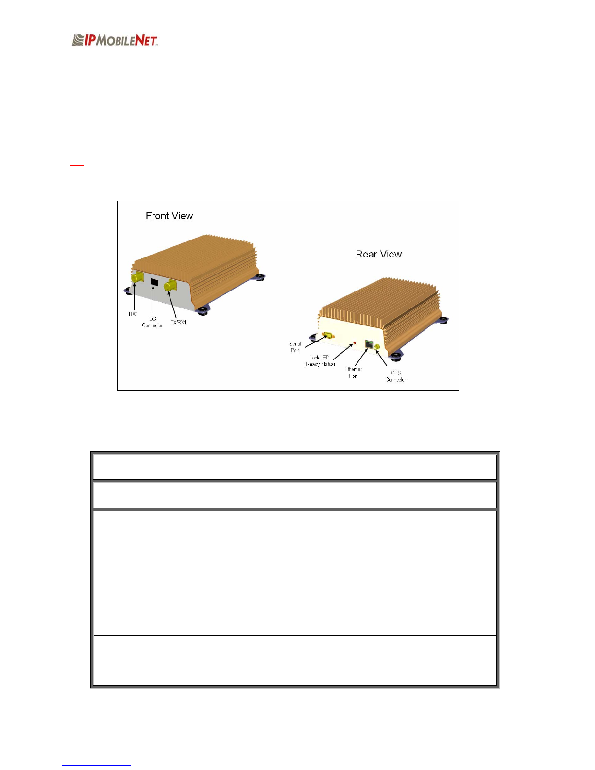
External Features ........................................................................................................................ 4
SECTION 2: SETUP AND CONFIGURATION METHODS .....................................................................5
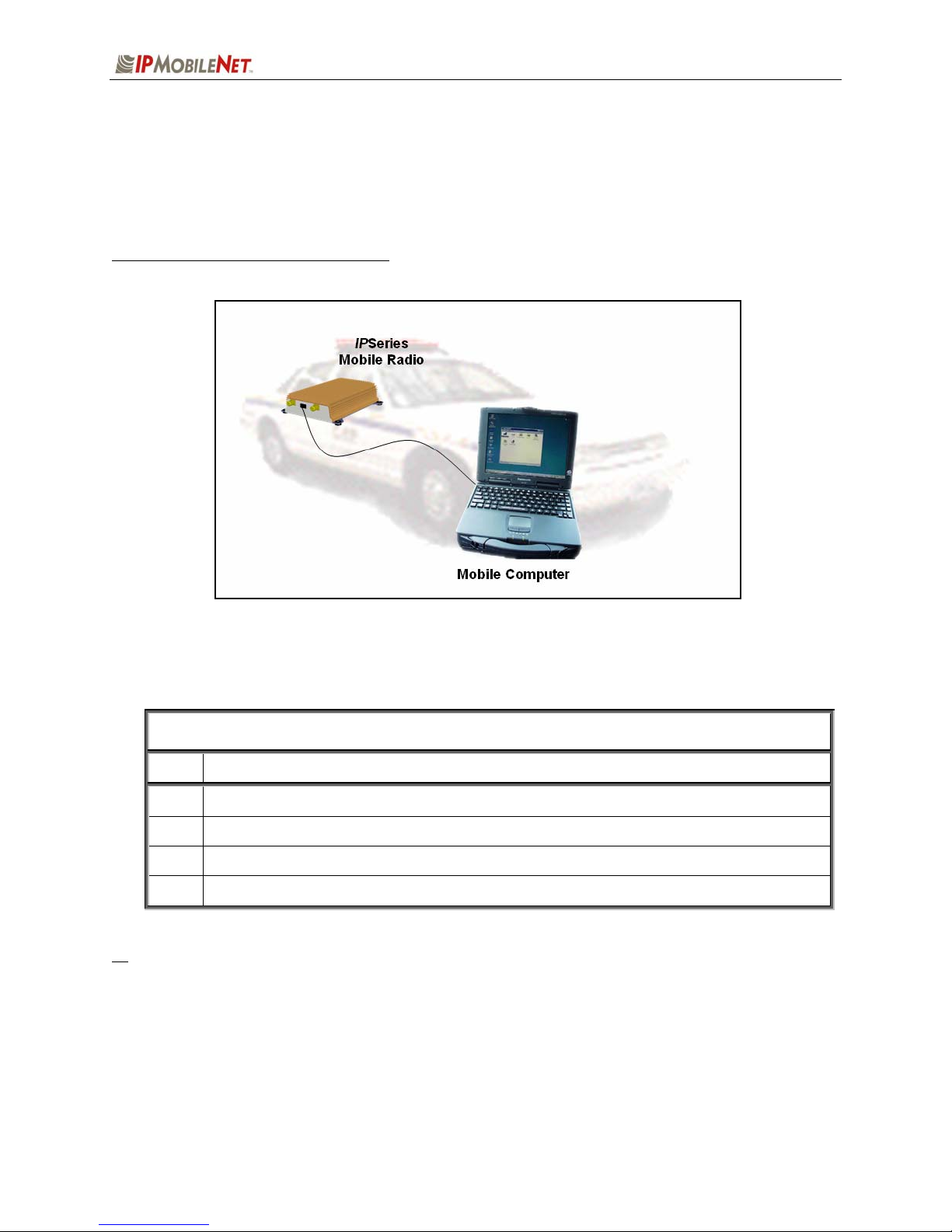
High Speed Mobile Radio Setup and Configuration Method..................................................5
Mobile Radio-to-Mobile Computer Setup......................................................................... 5
SECTION 3: INSTALLATION INSTRUCITONS ......................................................................................6
Installation Overview ..................................................................................................................6
Installation Instructions..............................................................................................................8
Pre-Installation Guidelines ...............................................................................................8
Mounting the High Speed Mobile Radio ..........................................................................9
Serial Cable Connection and Routing............................................................................10
Ethernet Setup ...............................................................................................................10
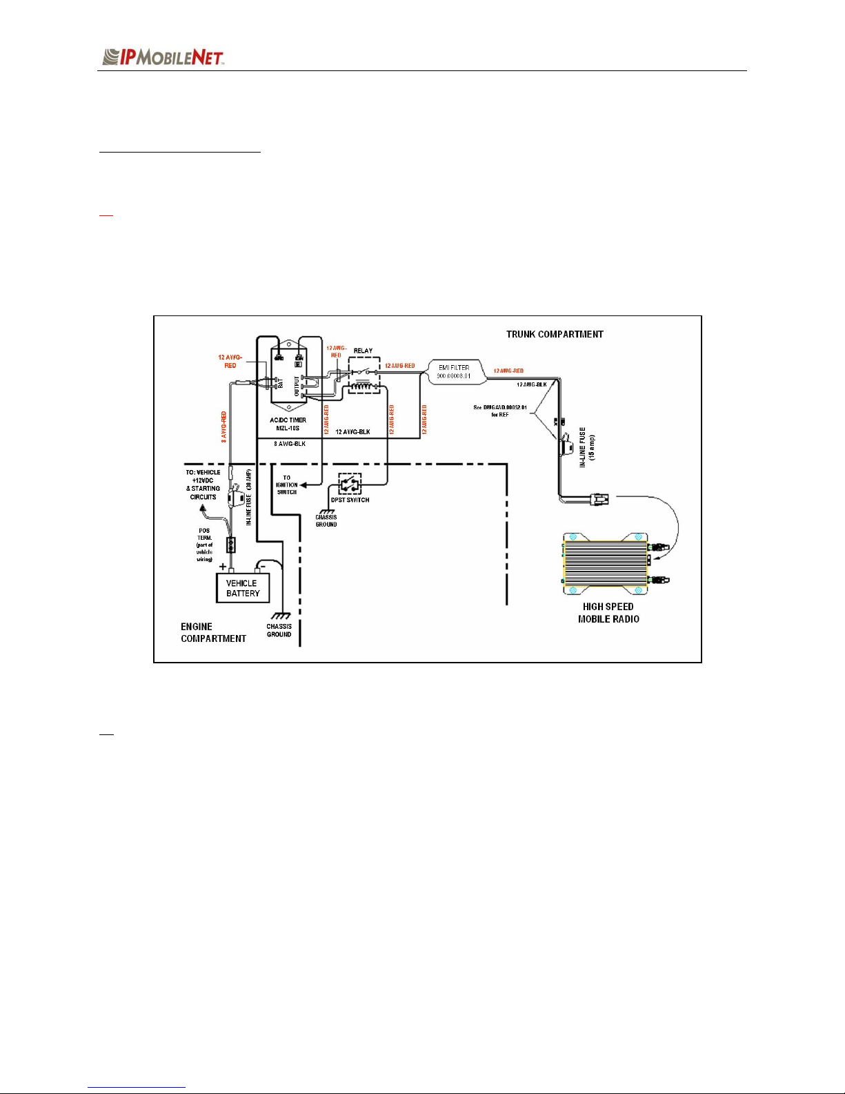
Delay Timer Installation .................................................................................................10
Carling Switch Installation (DPST Heavy Duty Toggle).................................................12
Mobile Radio Power Supply Installation.........................................................................13
Antenna Configuration ...................................................................................................14
Measuring Return Loss ...................................................................................15
Measuring Voltage Standing Wave Ratio .......................................................15
Measuring Insertion Loss ................................................................................16
Post Installation Checklist ..............................................................................................16
Mobile Installation Layout Diagrams ......................................................................................17
Preliminary Testing and Troubleshooting..............................................................................19
Checklist of Requirement Materials ...............................................................................19
Base Station Setup for Testing ......................................................................................20
Preliminary Test Procedure and Troubleshooting ................................................................21
Confirming High Speed Mobile Radio Receiver Sensitivity ...........................................24
SECTION 4: FACTORY TEST PROCEDURE .......................................................................................25
Equipment List .........................................................................................................................25
Programming and Configuring Mobile Radio ........................................................................26
Adjustment / Alignment Procedures....................................................................................... 27
Receiver Injection...........................................................................................................27
Receiver1
......................................................................................................................27
Receiver2......................................................................................................................27
TransmitData
.................................................................................................................28
Power Setting.................................................................................................................28
ReceiveData..................................................................................................................29
Final Test .......................................................................................................................29
Uplink Hardware Timing Verification..............................................................................31
Downlink Hardware Timing Verification .........................................................................33
SECTION 5: FCC LABEL.......................................................................................................................35
M64700G25 Data Transceiver FCC Label Placement ............................................................35
M64700G25 Data Transceiver FCC Label ...............................................................................35
APPENDIX A: M64700G25 CIRCUIT BOARD DIAGRAMS .................................................................36
APPENDIX B: M64700G25 TEST DATA SHEET..................................................................................37

SECTION 1: OVERVIEW
M64700G25-FCCRpt.doc Page 3
Product Description
The M64700G25 Mobile Radio works within a frequency range of 794-806 MHz and requires a 1/4-wavelength
antenna.
The IPSeries High Speed Mobile Radios are intelligent devices designed for the challenging requirements
of mobile data applications. Mounted in vehicles, other intelligent devices may connect to the serial or
Ethernet ports for connectivity back to the Internet Protocol Network Controller (IPNC) and other such
servers. It provides the mobile link to land-based wired networks. The high speed mobile radio circuit
boards are built using surface mount technology (SMT) and through-hole components.
Figure 1: IPSeries High Speed Mobile Radio (Front View)
Product Functionality
The high speed mobile radio utilizes a high-performance, 32-level QAM. Further it uses state-of-the-art
OFDM technique. This new technique will enable the high speed mobile radio to transmit and receive
more than 100 Kbps data in a 25 kHz band. The high speed mobile radio features low power
consumption, high performance integrated GPS receiver. Embedding this technology in the mobile radio
lowers the cost of acquiring GPS data from vehicles and ensures optimal performance.
The high speed mobile radio technology includes Diversity Reception (DR) capability. DR reduces the
effects of fades in a multi-path environment. With the use of two (2) antennas mounted at a calculated
distance on the roof of the vehicle the Diversity Reception System (DRS) minimizes the effects of fading
by intelligently selecting the receiver with a better signal.
Diversity is most effective when the vehicle is in motion.

SECTION 1: OVERVIEW
M64700G25-FCCRpt.doc Page 4
External Features
As seen in Figure 2 below, the IPSeries High Speed Mobile Radio technology is enclosed in a compact
and sturdy aluminum case. The external features consist of a series of connectors and ports as
described in this section.
aThe product warranty becomes void if an uncertified or unauthorized individual removes the
mobile radio cover.
Figure 2: IPSeries High Speed Mobile Radio (External Features)
The high speed mobile radio external features consist of the following connectors and ports:
TABLE 1: EXTERNAL FEATURES
FEATURE DESCRIPTION
TX/RX1 Transmitter / Receiver 1 antenna connection
RX2 Receiver 2 antenna connection
Power Connector 13.8 VDC high speed mobile radio power connector
Lock LED Unit ‘Ready’ Status Indicator LED (light emitting diode)
GPS GPS antenna (SMA) connector
Serial Port RS232 Serial Line Internet Protocol (SLIP) interface port
Ethernet Port 10 Base T Ethernet interface port

SECTION 2: SETUP AND CONFIGURATION METHOD
M64700G25-FCCRpt.doc Page 5
Mobile Radio-to-Mobile Computer Setup and Configuration
The following section describes the setup and configuration method for the high speed mobile radio in a
vehicle.
Mobile Radio-to-Mobile Computer Setup
Figure 3: High Speed Mobile Radio-to-Mobile Computer Setup
Additional components are required to setup a high speed mobile radio-to-mobile computer configuration,
and are listed below in Table 2:
TABLE 2: HIGH SPEED MOBILE RADIO-TO-MOBLE COMPUTER COMPONENTS
REQUIRED FOR INSTALLATION
QTY DESCRIPTION
1 IPSeries High Speed Mobile Radio
1 Mobile Computer
1 20-foot serial cable (DB9F – DB9M)
1 IPMobileNet SLIP Port Driver Installation Diskette (SLIP2IPMN.exe)
If using the high speed mobile radio’s Ethernet feature an Ethernet crossover cable is required to
replace the 20-foot serial cable.
To configure the high speed mobile radio and computer for this type of setup, follow the
instructions on pages 2 through 17 in the Mobile Computer Setup for Communication with the
Mobile Radio Installation Guide (IPMN p/n: 516.80310.IG) available on the Product
Documentation CD.

SECTION 3: INSTALLATION INSTRUCTIONS
M64700G25-FCCRpt.doc Page 6
Installation Overview
This chapter provides the basic steps involved in the installation process of an IPSeries High Speed
Mobile Radio into a vehicle. This chapter includes wire routing and connections between the high speed
mobile radio, other components, and the vehicle’s power.
aTo prevent personal injury and vehicle damage, exercise extreme caution throughout the
installation process and follow the reminders listed below.
Follow safety precautions for handling wiring, tools, and a vehicle’s engine.
Handle the vehicle’s battery with extreme caution to avoid burns.
Do not alter the components listed in the Installation Requirements section below, unless
substitutions are noted within this chapter.
Once the antennas are installed, as directed within this user manual, all persons must
maintain a distance of no less than 39 inches from the antennas while the high speed mobile
radio is in the transmit mode.
Installation Requirements
Table 3 lists the documents required to successfully install the high speed mobile radio and connect to
the various components within the vehicle:
TABLE 3: DOCUMENTS REQUIRED FOR HIGH SPEED MOBILE RADIO INSTALLATION
DESCRIPTION PART NUMBER
The following documents are available on the Product Documentation CD
enclosed in the shipment with the high speed mobile radio: 480.0001.001
M64700G25 High Speed Mobile Radio Product Owner’s Manual 516.80528.POM
Installation Guide for Mobile Computer Setup for Communication with
the Mobile Radio 516.80310.IG

SECTION 3: INSTALLATION INSTRUCTIONS
M64700G25-FCCRpt.doc Page 7
Table 4 lists the components required to perform a successful high speed mobile radio installation and
are available for purchase through IPMobileNet, Inc.
TABLE 4: MOBILE INSTALLATION ACCESSORIES KIT
QTY DESCRIPTION IPMN PART NUMBER
4 Screws, Self Tapping #10 X 5/8 37040010-10
1 EMI Filter 127.0020.002
1 Timer, 2 hours 150.0127.004
1 Relay 128.0117.001
1 Relay Socket 128.0116.001
2 Butt Connectors #8 AWG 120.0256.001
1 Terminal, Ring #8 AWG, #10 Screw Insulated 120.0127.001
4 Terminal, Ring #18-22 AWG, #10 Screws Insulated 120.0250.004
4 Terminal, Ring #10-12 AWG, #10 Screws Insulated 120.0250.005
4 Terminal, Disconnect #14-16 F 120.0244.002
18 Terminal, Disconnect #10-12 F 120.0244.003
2 Disconnect Tab, Quad Male 200.1377.001
1 Wire, 12 AWG Black, order 5 ft. 156.0242.001
1 Wire, 12 AWG Red, order 44 ft. 156.0242.003
1 Fuse, 15 AMPS ATO 122.0042.003
2 Fuse, 30 AMPS ATO 122.0042.001
3 Fuse Holder, 12 AWG 120.0253.001
1 Switch, Toggle DPST 144.0136.001
1 Diagram, Mobile Installation (included in this manual) 502.80259.52
1 Diagram, Diversity Antenna Mobile Installation Detail (Typical Install) DT450-10-0201
Table 5 lists the auxiliary equipment required to complete the installation process.
TABLE 5: AUXILIARY EQUIPMENT
QTY DESCRIPTION IPMN PART NUMBER
1 Serial Cable (DB9MF), 20 ft. 156.0245.020
1 Wire, 8 (133/29) AWG VW-1 Red, by foot, order 19.5 ft. 156.0243.003
1 Wire, 8 (133/29) AWG VW-1 Black, by foot, order 19.5 ft. 156.0243.001
2 RG8X Cable and Mount, 800 MHz, 17 ft. (incl ¾“ Brass Mount & N
Male Crimp) 102.0200.002
2 Antenna, Radome type, 806-866 MHz, 3dB Gain (requires 1 MB8XN
for ea antenna) 102.0207.001
2 Antenna, Radome Type 821-896 MHz, 3dB Gain (requires 1 MB8XN
for ea antenna) 102.0207.002
2 Antenna, 5/8 Wave, 806-866 MHz, 3dB Gain (requires 1 MB8XN for
ea antenna) 102.0199.001
2 Antenna, ¼ Wave, 806-896 MHz, Unity Gain (requires 1 MB8XN for
ea antenna) 102.0204.010

SECTION 3: INSTALLATION INSTRUCTIONS
M64700G25-FCCRpt.doc Page 8
Installation Instructions
Pre-Installation Guidelines
Prior to installing new equipment, perform the following steps:
a1. Remove existing equipment and all related components to include stock clips on radio
wiring harness and antenna.
2. As shown in the figure below, mounting of the high speed mobile radio, delay timer, relay,
and EMI filter (noise filter) will take place in the trunk compartment, unless installing in a
vehicle without a trunk.
Figure 4: Trunk Compartment Installation
Removal of seats, rubber mats, and other obstructions from inside the driver compartment may
be necessary to facilitate routing of wires to the engine and trunk compartments.
3. To ensure appropriate cable and wire routing, exercise the following precautions:
Route cables away from sharp edges that can penetrate cable insulation and damage
wires.
Protect wires with silicone rubber grommets when routing through the engine
compartment firewall or through other holes with sharp edges.
Use high-quality electrical tape when covering exposed wires in the engine
compartment.
Avoid routing cables through areas exposed to extreme heat, such as the exhaust.
Keep wires routed through the engine compartment away from hot and/or moving
parts.

SECTION 3: INSTALLATION INSTRUCTIONS
M64700G25-FCCRpt.doc Page 9
4. Prior to drilling holes in the engine compartment firewall, inspect both sides to avoid
obstructions.
5. For grounding point, use the engine block or the negative (-) terminal of the vehicle battery.
Ground connection surfaces must be free of paint, rust, and other corrosion to maximize
performance and avoid damage. Do not tie to the vehicle chassis.
6. To simplify troubleshooting problems, label all connecting points and wires.
Mounting the High Speed Mobile Radio
To mount the high speed mobile radio, perform the following steps:
Step 1 As shown in the figure below, secure the high speed mobile radio into the trunk
compartment. Insert four (4) sheet metal screws in the high speed mobile radio
brackets.
Figure 5: High Speed Mobile Radio Mounting
aIf less than four (4) screws are used, the high speed mobile radio can become loose in the trunk
compartment. This may cause the high speed mobile radio not to function properly.
When inserting screws, be careful not to disturb the vehicle’s gas tank.

SECTION 3: INSTALLATION INSTRUCTIONS
M64700G25-FCCRpt.doc Page 10
Serial Cable Connection and Routing
The serial cable connects the mobile radio to the mobile computer located in the driver compartment.
To connect the serial cable, perform the following steps:
Step 1 Attach the 20-foot serial cable male connector (DB9M – see Figure 6)
to the mobile radio.
Step 2 Route the female connector (DB9F – see Figure 7) to the driver
compartment and connect to the serial port located on the rear of the
mobile computer.
Route the serial cable to minimize foot pressure and other potential stresses. Use split
loom tubing and nylon cable ties for cable protection.
Ethernet Setup
The user also has the option to connect the mobile radio and the mobile computer via Ethernet.
To connect the Ethernet crossover cable, perform the following steps:
Step 1 Attach the Ethernet crossover cable (minimum 20 feet) to the Ethernet port on the rear
of the mobile radio.
Step 2 Route the other end of the Ethernet crossover cable to the driver compartment and
connect to the Ethernet port located on the rear of the mobile computer.
Route the cable to minimize foot pressure and other potential stresses. Use split loom
tubing and nylon cable ties for cable protection.
Delay Timer Installation
To install the Delay Timer, perform the following steps:
Step 1 Secure Delay Timer to the trunk compartment of the vehicle inserting screws in the
appropriate locations using care not to puncture the vehicle’s gas tank.
Step 2 Route the black wire (#12 AWG) from ground connection on the Delay Timer to the
vehicle chassis (see Figure 9).
Step 3 Route and wire the red wire (#8 AWG) from the positive (+) terminal connection on
the vehicle battery connection via the in-line fuse toward the battery connection on
the Delay Timer.
Connect the red wire (#8 AWG) to the two red wires (#12 AWG). Route and wire the
red (#12 AWG) wires to the two (2) battery connections on the Delay Timer.
Figure 6
Figure 7

SECTION 3: INSTALLATION INSTRUCTIONS
M64700G25-FCCRpt.doc Page 11
Figure 8: Delay Timer Installation
Step 4 Route a red wire (#12 AWG) from the ignition connection on the Delay Timer to the
ignition switch in the driver compartment (see the figure above). The ignition wire
should be fused with 2A fuse.
Step 5 Route a red wire (#12 AWG) from the first and last output connections on the Delay
Timer to the Automotive Power Relay.
Step 6 Route and wire a red (#12 AWG) wire from the second output connection on the
Delay Timer to the last output connection on the Delay Timer.
Step 7 Route and wire a red (#12 AWG) wire from the last output connection on the Delay
Timer to the Automotive Power Relay coil at the position shown in the figure above.
Step 8 Route and wire a black (#8 AWG) wire from the junction (negative battery post
group) in the trunk compartment to the negative (-) terminal on the vehicle battery.
Step 9 Wire the red (#12 AWG) wire to the battery input on the Delay Timer and route the
black (#8 AWG) portion of the wire to the positive terminal on the battery via an in-
line fuse (30 AMP).

SECTION 3: INSTALLATION INSTRUCTIONS
M64700G25-FCCRpt.doc Page 12
Carling Switch Installation (DPST Heavy Duty Toggle)
To install the switch, perform the following steps:
Step 1 Mount the switch in the selected location.
Step 2 Route and wire a red wire (#12 AWG) from the switch to the Automotive Power Relay
(see the figure below).
Step 3 Ground the switch by routing and wiring a black wire from the switch to the chassis
ground.
Figure 9: Carling Switch Installation

SECTION 3: INSTALLATION INSTRUCTIONS
M64700G25-FCCRpt.doc Page 13
Mobile Radio Power Supply Installation
To install the mobile radio power connection, perform the following steps:
Step 1 Route and connect the power cable to the EMI filter, as shown in the figure below.
Figure 10: Power Supply Installation
Step 2 Route and connect the other end of the power cable to the rear of the mobile radio
to the power connector (13.8 VDC) connection.
aWARNING! Do not connect power before installing and connecting proper antenna or dummy
load on the TX/RX1 port. The mobile radio must never be allowed to transmit without a suitable
output load.
Step 3 Install the GPS antenna. The GPS antenna is required for the mobile radios and
the base stations.

SECTION 3: INSTALLATION INSTRUCTIONS
M64700G25-FCCRpt.doc Page 14
Antenna Configuration
Two (2) antennas are mounted and installed on the roof of the vehicle using specific
measurements for distance.
To mount and install the antennas, perform the following steps:
Step 1 Install antennas (see the figure below).
Observe correct separation between antennas (refer to Table 7: Mobile Antenna
Distance Matrix). This table provides midpoint distance calculations and minimum and
Near-Field Exclusion Zone (NFEZ) for proper diversity reception.
aThe NFEZ distance is an absolute minimum. The greater the distance between the
antennas to any other surfaces will result in improved performance.
Step 2 Cut a mounting hole in the roof of the vehicle using an electric drill or hole saw.
The antenna-mounting hole provides ground connection to the antenna. Ensure that a
metal-to-metal connection between the antenna shields exists.
Figure 11: Antenna Distance Configuration
1 2

SECTION 3: INSTALLATION INSTRUCTIONS
M64700G25-FCCRpt.doc Page 15
The previous figure represents the recommended front-to-rear antenna installation. The
receiver antenna (RX2) should be the antenna nearest to the light bar.
Step 3 All antenna mounts must be environmentally tight. Install or use O-rings to seal the
antenna base to the rooftop of the vehicle.
Step 4 Route the coaxial cables to the mobile radio through one of the hollow spaces in the
roof supports into the trunk compartment where the high speed mobile radio is
mounted.
Both antennas should be checked and tested to ensure they are functioning properly.
aIf these installation guidelines are followed, it will be safe for persons to stand at a
distance no less than 39 inches from the antennas while the mobile radio is in
transmit mode.
Measuring Return Loss
The following test is performed without any power, thus can be performed immediately after the
installation of the coax and antenna, following the installation of the N-type connector on the coax.
To measure Return Loss, perform the following steps:
Step 1 Select the appropriate Antenna Analysts to perform the test.
Step 2 Connect the antenna to be tested to the Antenna Analyst.
Step 3 Turn on the Antenna Analyst and the Return Loss (RETL) is displayed in dB to the
left of the Voltage Standing Wave Ratio (VSWR) curve.
The Return Loss Specification is –14 dBm or greater (with good antennas the typical
range will be between –14 and –28).
Measuring Voltage Standing Wave Ratio
To measure the Voltage Standing Wave Ratio (VSWR) Reflected Power, perform the following
steps:
Step 1 After selecting the appropriate Analyst and connecting the antenna to be tested,
press F1 to access the Analyst Menu.
Step 2 Press F1 again to access the Display (DSPLY) menu, which lists the modes.
Step 3 Press F2 to select the VSWR display mode. Plotting will resume and the VSWR
value is highlighted.
The VSWR Reflected Power Specification should be at a ratio of approximately 1.6 to 1.

SECTION 3: INSTALLATION INSTRUCTIONS
M64700G25-FCCRpt.doc Page 16
Measuring Insertion Loss
To measure Insertion Loss of an unterminated length of coax, perform the following steps:
Step 1 Connect the antenna to be tested to the appropriate Antenna Analyst.
Step 2 Turn on the Antenna Analyst and the Return Loss is displayed in dB to the left of the
VSWR curve.
To switch from the RETL mode to VSWR mode, refer back to the previous set of
instructions.
Step 3 Divide the result by two (2).
Post Installation Checklist
Table 6 lists the tasks that should be performed upon completing installation.
TABLE 6: POST INSTALLATION CHECKLIST
NO. CHECKLIST ITEM ;
1 Scope out the entire vehicle setup to locate any obvious problem areas.
2 Check wiring for safety concerns.
3 Use tie wraps to ensure that all wires routed in parallel are bundled together.
4 Check to see if any wires are exposed.
5
If any wires are exposed, use electrical tape to cover.
When covering wires in the engine compartment, use high-quality
electrical tape.
6 Perform appropriate testing as described in this manual to ensure mobile radio
works properly.
Once installation is completed, remove all debris and restore dismantled parts and rubber mats to
appropriate locations.

SECTION 3: INSTALLATION INSTRUCTIONS
M64700G25-FCCRpt.doc Page 17
Mobile Installation Layout Diagrams
Figure 12 Vehicle Unit Wiring Interconnection Layout
Table 7 lists the high speed mobile radio antenna distances by frequency band.
TABLE 7: MOBILE ANTENNA DISTANCE MATRIX
Frequency
Band in MHz
Center
Frequency in
MHz
Antenna
Spacing for
¼ Wave Ant
(inches)
Wavelength
(inches)
Near-Field
Exclusion
Zone*
(inches)
¼ Wave
Length
(inches)
130-140 135 65.4 87.3 10.9 21.8
140-150 145 61.2 81.4 10.2 20.4
150-160 155 57.0 76.2 9.5 19.0
160-174 167 53.1 70.7 8.9 17.7
450-470 460 19.2 25.7 3.2 6.4
470-490 480 18.6 24.6 3.1 6.2
490-512 501 17.7 23.6 2.9 5.9
764-784 774 11.4 15.26 1.91 3.81
784-804 794 11.2 14.88 1.86 3.72
806-821 814 10.8 14.5 1.8 3.6
*NFEZ = Minimum Near-Field Exclusion Zone **Round antenna spacing to the nearest ⅛”

SECTION 3: INSTALLATION INSTRUCTIONS
M64700G25-FCCRpt.doc Page 18
Figure 13 Diversity Antenna Mobile Installation Detail (Typical Installation)

SECTION 3: INSTALLATION INSTRUCTIONS
M64700G25-FCCRpt.doc Page 19
Preliminary Testing and Troubleshooting
This section provides a functional preliminary test for the mobile radio once installed. It is used to
determine the condition of new mobile radios before being placed into service.
Checklist of Required Material
Table 8 provides a checklist of the tools and equipment required to perform the preliminary test
procedure.
TABLE 8: CHECKLIST OF REQUIRED MATERIAL TO PERFORM PRELIMINARY TESTING
NO. REQUIRED TOOLS/EQUIPMENT ;
1 IPSeries High Speed Mobile Radio installed in the vehicle as previously described
in this chapter
2 A laptop with an available serial communication port and Microsoft Windows 98 or
greater installed
3 IPMobileNet Dial-Up Networking and IPMessage software loaded onto the laptop
(SLIP2IPMN.exe)
4 DC power supply with ammeter, 13.8V, 12 amps or more (Astron VS12M or
equivalent)
5 Corresponding calibrated IPSeries Base Station
6 Internet Protocol Network Controller (IPNC)
7 Two antennas (generic mag mounts) tuned to frequency of transceiver
8 Serial cable DB9M – DB9F connectors (IPMN p/n: 156.0245.020)
9 RF Attenuator 10-20 dB with appropriate wattage rating for transceiver
Table of contents
Other IPMobileNet Radio manuals

IPMobileNet
IPMobileNet IP Series User manual

IPMobileNet
IPMobileNet IP Series User manual

IPMobileNet
IPMobileNet M64780D25 User manual

IPMobileNet
IPMobileNet IPM8 User manual

IPMobileNet
IPMobileNet M1617-12 User manual

IPMobileNet
IPMobileNet M64800D25 User manual

IPMobileNet
IPMobileNet F32700N25 User manual

IPMobileNet
IPMobileNet IPM4 User manual
Popular Radio manuals by other brands

Denver
Denver TR-54 operating instructions

Innovative Technology
Innovative Technology ITSB-353 instruction manual

Sony
Sony Shower Mate ICF-S70 operating instructions

MFJ Enterprises
MFJ Enterprises Grandmaster MFJ-484 owner's manual

Hypercable
Hypercable HYC-4009-30 user manual

Matsui
Matsui M1DAB11E instruction manual