IPS IPS-600 User manual

Thank you for choosing Full-Inverter heat pump.
This manual provides you necessary information for optimal
use and maintenance, please read it carefully and keep it for
subsequent use.
INSTALLATION AND
USER MANUAL
EN / DE

Summary
1. General information ................................................................................................................ - 1 -
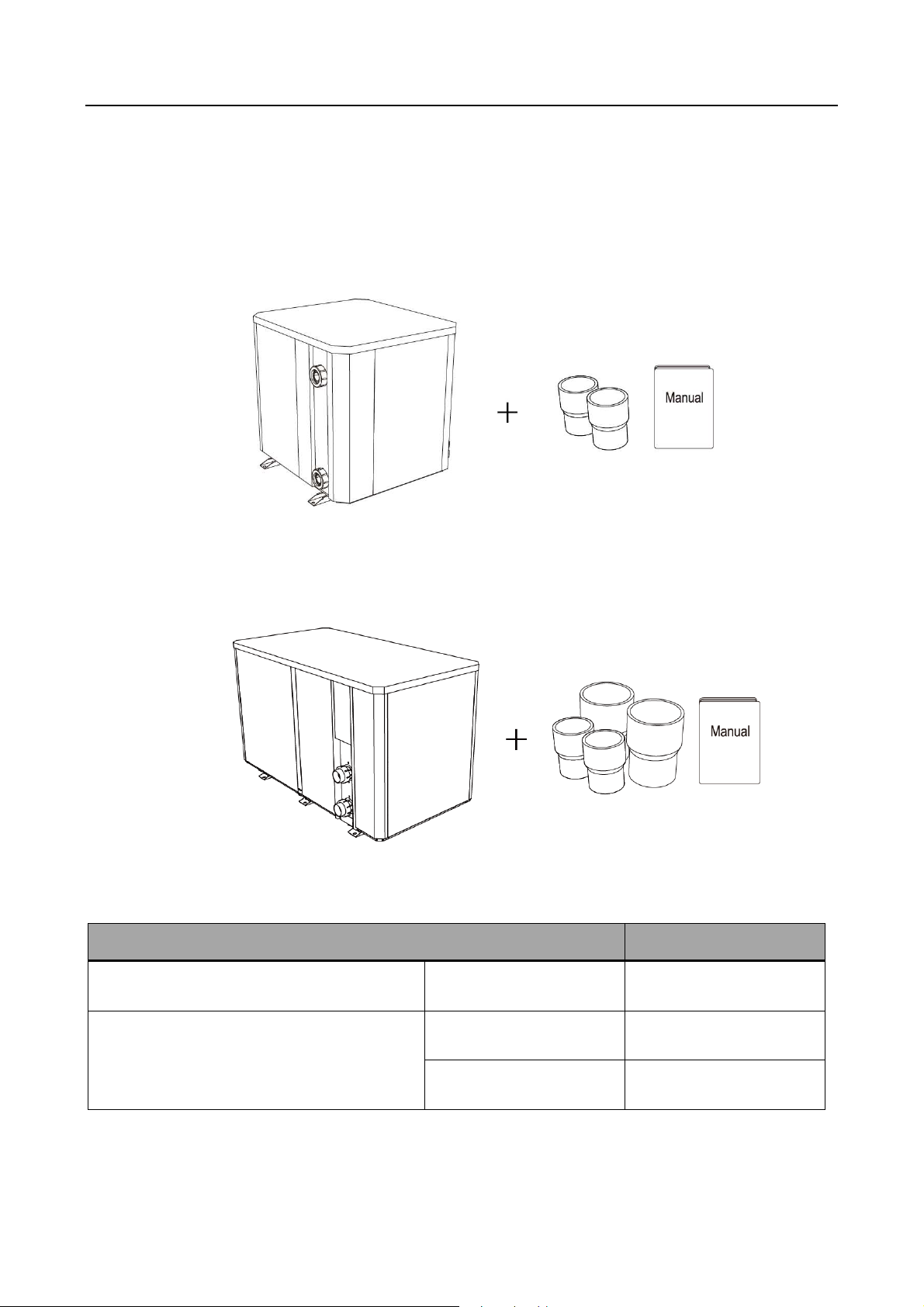
1.1. ontents .............................................................................................................................. - 1 -
1.2. Operating conditions and range ........................................................................................... - 1 -
1.3. Advantages of different modes ............................................................................................. - 2 -
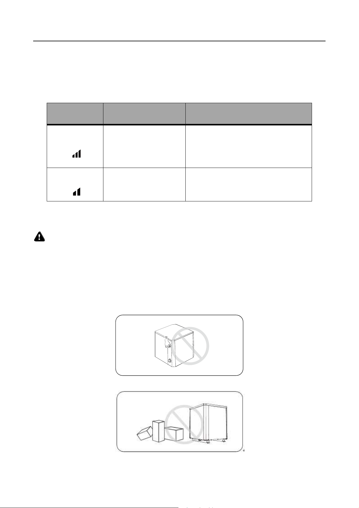
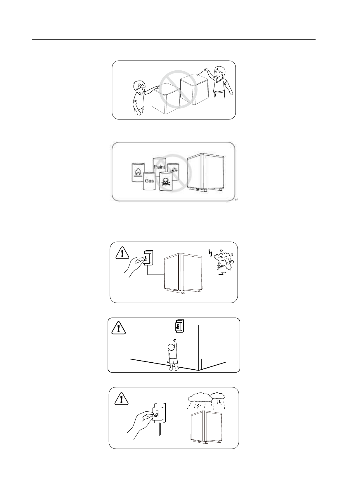
1.4. Kind reminder ....................................................................................................................... - 2 -
2. Operations .............................................................................................................................. - 4 -
2.1. Notice before using .............................................................................................................. - 4 -
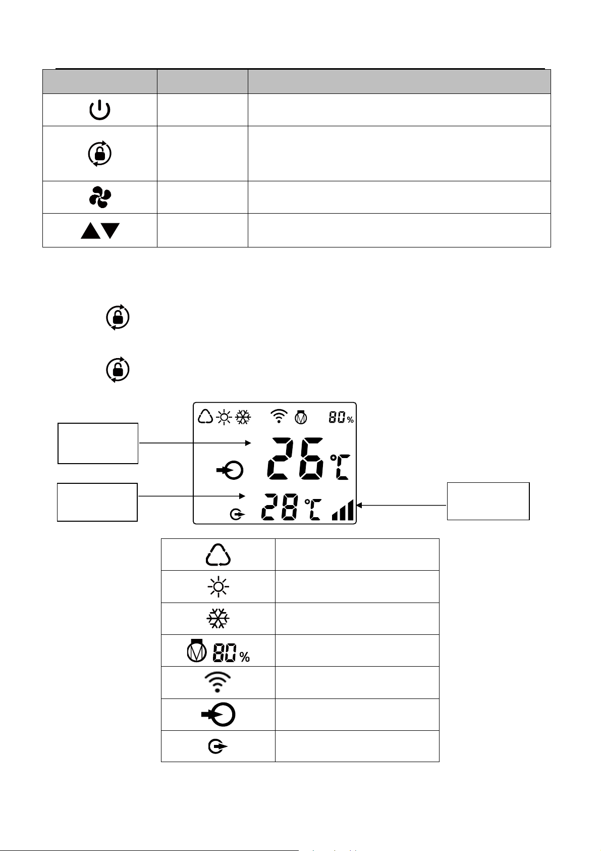
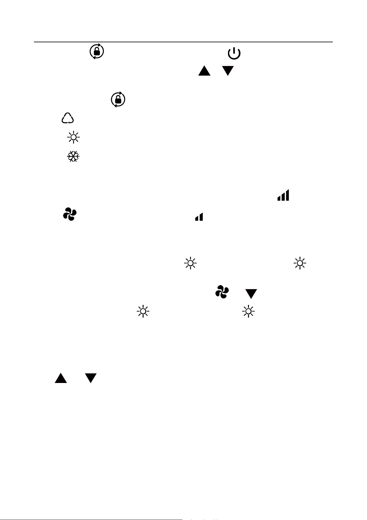
2.2. Operation instructions .......................................................................................................... - 4 -
2.3. Daily maintenance and winterizing ....................................................................................... - 7 -
3. Technical specification ............................................................................................................ - 8 -
1. Transportation ......................................................................................................................... - 9 -
2. Installation and maintenance ................................................................................................. - 10 -
2.1. Notice before installation: ................................................................................................ - 10 -
2.2. Installation instruction ......................................................................................................... - 10 -
2.3. Trial after installation .......................................................................................................... - 15 -
2.4. Maintenance and winterizing .............................................................................................. - 16 -
3. Trouble shooting for common faults ...................................................................................... - 16 -
4. Failure code .......................................................................................................................... - 17 -
Appendix 1: Heating priority wiring diagram (Optional) .............................................................. - 18 -
5.
Wifi setting ............................................................................................................................. - 20 -
For users ……………………………………………………………………………….
P.1
-
P.
8
Fo
r installers and professionals
…………
………………………………………
P.
9
-
P.2
5

For users
- 1 -
1. General information
1.1. Contents
After unpacking, please check if you have all the following components.
OR
1.2. Operating conditions and range
Items Range
Operating range Air temp
-7℃~43℃
Temp. setting
heating
18℃~40℃
cooling
12℃~30℃
The heat pump will have ideal performance in the operation range Air 1
℃~
2
℃

For users
- 2 -
1.3. Advantages of different modes
The heat pump has two modes: Smart and Silence. They have different advantages under
different conditions.
1.4. ind reminder
This heat pump has Power-off memory function. When the power is recovered, the heat
pump will restart automatically.
1.4.1. The heat pump can only be used to heat the pool water. It can NEVER be used to
heat other flammable or turbid liquid.
1.4.2. Don’t lift the water union when moving the heat pump since the titanium heat
exchanger inside the heat pump will be damaged.
1.4.3. Don’t put obstacles before the air inlet and outlet of the heat pump.
MODE RECOMMENDATION ADVANTAGES
Smart mode
As standard
Heating capacity: 20% to 100% capacity
Intelligent optimization
Fast heating
Silent mode
Use at night Heating capacity: 20% to 80% capacity

For users
- 3 -
1.4.4. Don’t put anything into inlet or outlet, or the efficiency of the heat pump will be
reduced or even stopped.
1.4.5. Don’t use or store combustible gas or liquid such as thinners, paint and fuel to avoid
fire.
1.4.6. If any abnormal circumstances occurred, e.g.: abnormal noises, smells, smokes and
leakage of electricity, switch off the main power immediately and contact your local
dealer. Don’t try to repair the heat pump by yourselves.
1.4.7. The main power switch should be out of the reach of hildren.
1.4.8. Please cut off the power in the lightning storm weather.

For users
- 4 -
1.4.9. Please note that following codes are not failure.
Description
Codes
No water flow
Anti-Freezing Reminder
Out of the operating range
Insufficient water flow or pump
blocked
Power abnormal
2. Operations
2.1. Notice before using
①
For longer service life, please ensure water pump is on before heat pump is on, and
water pump is off after heat pump is off.
② Ensure no water leakage on piping system, then unlock screen and power on heat
pump.
2.2. Operation instructions

For users
- 5 -
Symbol Designation Function
ON/OFF 1. Power On/Off
2. Wifi setting
Unlock / Mode
1. Press it for 3 seconds to unlock/lock screen.
2. After screen is unlocked, press it to select mode.
Auto (12~40℃) Heating (18~40℃) ooling (12~30℃)
Speed Select Smart/Silence mode
Up / Down Adjust set temperature
Note:
① Screen lock:
a. If no operation in 30 seconds, screen will be locked.
b. When HP is off, screen will be dark and “0%” will be displayed.
c. Press for 3 seconds to lock screen and it will be dark.
② Screen unlock:
a. Press for 3 seconds to unlock screen and it will be lit up.
b. Only after screen is unlocked, any other buttons can be functioned.
Auto
Heating
ooling
Heating capacity percentage
Wifi connection
Water inlet
Water outlet
Water inlet
temperature
Water outlet
temperature
Smart/Silence
mode

For users
- 6 -
1.Power On: Press for 3 seconds to light up screen, then press to power on heat pump.
2.Adjust Set Temperature: When screen is unlocked, press or to display or adjust the set
temperature.
3. Mode Selection: Press to select mode.
a. Auto : adjustable temperature range 12~40℃
b. Heating : adjustable temperature range 18~40℃
c. ooling : adjustable temperature range 12~30℃
4. Smart/Silence mode selection:
①
Smart mode as default will be activated when heat pump is on, and screen shows .
② Press to enter Silence Mode
, and screen shows .
(Suggestion: select Smart mode for initial heating)
5. Defrosting
a. Auto Defrosting: When heat pump is defrosting, will be flashing. After defrosting, will stop
flashing.
b. ompulsory Defrosting: When heat pump is heating, press and together for 5 seconds to
start compulsory defrosting, and will be flashing. After defrosting, will stop flashing.
(Note: ompulsory defrosting intervals should be more than 30 minutes and the compressor should run for
more than 10 minutes.)
6. Temperature display conversion between ℃ and ℉:
Press " " and " " together for 5 seconds to switch between ℃ and ℉.
7. Wifi setting
Please kindly check the last page.

For users
- 7 -
2.3. Daily maintenance and winterizing
2.3.1. Daily Maintenance
Please don’t forget to cut off power supply of the heat pump.
Please clean the evaporator with household detergents or clean water, NEVER use
gasoline, thinners or any similar fuel.
heck bolts, cables and connections regularly.
2.3.2. Winterizing
In winter season when you don’t swim, please cut off power supply and drain water out
of the heat pump. When using the heat pump under 2℃, make sure there is always
water flow.
Important:
Unscrew the water union of inlet pipe
to let the water flow out.
When the water in machine freezes in
winter
season, the titanium heat
exchanger may be damaged.

For users
- 8 -
3. Technical specification
Model IPS-600 IPS-1200
Advised pool volume (m
3
) 130~260
260~520
Operating air temperature (℃) -7~43
Performance Condition: Air 26°C, Water 26°C,
Humidity 80%
Hea
ting capacity (kW)
60.0
110.0
OP at 50% capacity 10.1 10.0
Performance Condition: Air 15°C, Water 26°C,
Humidity 70%
Heating capacity (kW)
40.0 81.0
OP at 50% capacity 6.8 6.8
Performance Condition: Air 35°C, Water 28°C, Humidity 80%
ooling capacity (kW) 26.5 54.0
Sound pressure at 1m dB(A) 54.0~62.0 56.0~65.0
Sound pressure of 50% capacity at 1m
dB(A) 56.0 58.0
Sound pressure at 10m dB(A) 34.0~42.0 36.0~45.0
ompressor D inverter
Heat exchanger Spiral titanium tube in PV
asing Aluminum-alloy
Fan direction Vertical
Power supply 400V/3Ph/50Hz
Rated input power at air 15° (kW) 2.20~8.03
4.69~17.6
Rated input current at air 15° (A) 3.17~11.59
6.77~25.4
Advised water flux (m³/h) 20~25
40~50
Water pipe in-out size (mm) 75
110
Net dimension LxWxH (mm) 1110x1023x1260
2100×1090×1280
Net weight (kg) 230
448
The values indicated are valid under ideal conditions: Pool covered with an isothermal cover,
filtration system running at least 1 hours a day.
Related parameters are subject to adjustment periodically for technical improvement without
further notice. For details please refer to nameplate.

For installers and professionals
- 9 -
1. Transportation
1.1. When storing or moving the heat pump, the heat pump should be at the upright
position.
1.2. When moving the heat pump, do not lift the water union since the titanium heat
exchanger inside the heat pump will be damaged.
1.3. Before moving the ommercial inverter, remove the screws which fixed on the pallet
and remove the pallet.
1. Remove the screws which fixed on the pallet
2. Deliver with fork lift

For installers and professionals
- 10 -
2. Installation and maintenance
The heat pump must be installed by a professional team. The users are not qualified to
install by themselves, otherwise the heat pump might be damaged and risky for users’
safety.
2.1. Notice before installation:
2.1.1. The inlet and outlet water unions can’t bear the weight of soft pipes. The heat pump
must be connected with hard pipes!
2.1.2. In order to guarantee the heating efficiency, the water pipe length should be ≤10m
between the pool and the heat pump.
2.2. Installation instruction
2.2.1. Location and size
The heat pump should be installed in a place with good ventilation
*
Distance Minimale
Fltre
Vannes hydrauliques
Traitement automatique

For installers and professionals
- 11 -
E
B
F
G
D
A
H
C
※
Above data is subject to modification without notice.
2.2.2. Heat pump installation.
The frame must be fixed by bolts (M10) to concrete foundation or brackets. The
concrete foundation must be solid; the bracket must be strong enough and anti-rust
treated;
The heat pump needs a water pump (Supplied by the user). The recommended pump
specification-flux: refer to Technical Parameter, Max. lift ≥10m
When the heat pump is running, there will be condensation water discharged from the
bottom, please pay attention to it.
UNIT=MM A B C D E F G H
Model IPS-600
1010
705
1110
1070
1023
780
105
1260
UNIT=MM A B C D E F G H
Model IPS-1200
1010
1630
1090
1050
2100
515
140
1280

For installers and professionals
- 12 -
2.2.3. Wiring & protecting devices and cable specification
onnect to appropriate power supply, the voltage should comply with the rated voltage
of the products.
Well earth the heat pump.
Wiring must be connected by a professional technician according to the circuit diagram.
Set breaker or fuse according to the local code (leakage operating current ≤ 30mA).
The layout of power cable and signal cable should be orderly and not affecting each
other.
1. How to connect to the terminal board
Step 1. Open the maintenance panel
IPS-600
Remove the screws
Open the front right panel and the internal
onnect the wire
Restore the internal panel and the front right
panel
Fix by screws

For installers and professionals
- 13 -
IPS-1200
Remove three screws outside
Open the panel
Remove two screws inside
Open the internal
Step 2. Power cord must be passed through below 3 holes
onnect the wire through three holes
Hole1 Hole2 Hole3

For installers and professionals
- 14 -
② Restore the internal panel
③ Fix the internal panel by two screws
Restore the panel
Fix the panel by three screws
2. Wiring diagram
Note:
Must be hard wired, no plug allowed.
For your safe use in winter, it’s strongly recommended to equip heating priority function.
For the detailed wiring diagram, please refer to Appendix 1.
Distribution Box ( ustomer prepare)
Power ord Swimming Pool Heat Pump Wiring Board
Power Supply
400V 50Hz
Breaker
For power supply: 400V 50Hz
Earthing
Fuse

For installers and professionals
- 15 -
3. Options for protecting devices and cable specification
MODEL
IPS-600 IPS-1200
Breaker
Rated Current (A) 23.0 45.0
Rated Residual
Action Current
(
mA
)
30 30
Fuse (A) 23.0 45.0
Power Cord (mm
2
) 5×6 5×16
Signal cable(mm
2
) 3×0.5 3×0.5
NOTE: The above data is adapted to power cord ≤ 10m. If power cord is
>
10m, wire diameter must be
increased. The signal cable can be extended to 0m at most.
2.3. Trial after installation
Please check all the wirings carefully before turning on the heat pump.
2.3.1. Inspection before use
heck installation of the whole heat pump and the pipe connections according to the
pipe connecting drawing;
heck the electric wiring according to the electrical wiring diagram and earthing
connection;
Make sure that the main power is well connected;
heck if there is any obstacle in front of the air inlet and outlet of the heat pump.
2.3.2. Trial
The user is advised to start the water pump before the heat pump, and turn off the heat
pump before the water pump for long life circle.
The user should start the water pump, and check for any leakage of water; Power on
and press the ON/OFF button of the heat pump, and set desired temperature in the
thermostat.
In order to protect the heat pump, the heat pump is equipped with start delay function.
When starting the heat pump, the fan will start to run in 3 minutes, in another 30
seconds, the compressor will start to run.
After pool heat pump starts up, check for any abnormal noise from the heat pump.
heck the temperature setting.

For installers and professionals
- 16 -
2.4. Maintenance and winterizing
2.4.1. Maintenance
The maintenance should be carried out once per year by qualified professional technician.
ut off power supply of the
heat pump before cleaning,
examination and repairing .
Do not touch the electronic
components until the LED
indication lights on P B turn off.
Please clean the evaporator with household detergents or clean water, NEVER use
gasoline, thinners or any similar fuel.
heck bolts, cables and connections regularly.
2.4.2. Winterizing
In winter season when you don’t swim, please cut off power supply and drain water out of
the heat pump. When using the heat pump under 2℃, make sure there is always water
flow.
3. Trouble shooting for common faults
Failure Reason Solution
Heat pump doesn’t run
No power Wait until the power recovers
Power switch is off Switch on the power
Fuse burned heck and change the fuse
The breaker is off heck and turn on the breaker
Fan running but with
insufficient heating
evaporator blocked Remove the obstacles
Air outlet blocked Remove the obstacles
3 minutes start delay Wait patiently
Display normal, but no
heating
Set temp. too low Set proper heating temp.
3 minutes start delay Wait patiently
If above solutions don’t work, please contact your installer with detailed information and your model
number. Don’t try to repair it yourself.
ATTENTION!Please don’t try to repair the heat pump by yourself to avoid any risk.
Important:
Unscrew the water union of inlet pipe
to let the water flow out.
When the water in machine freezes in
winter season, the titanium h
eat
exchanger may be damaged.

For installers and professionals
- 17 -
4. Failure code
NO. Display Not failure description
1 E3 No water protection
2 E5 Power supply excesses operation range
3 E6 Excessive temp difference between inlet and outlet water(Insufficient water flow
protection)
4 Eb Ambient temperature too high or too low protection
5 Ed Anti-freezing reminder
NO. Display Failure description
1 E1 High pressure protection
2 E2 Low pressure protection
3 E4 Phases lack protection (three phase model only)
4 E7 Water outlet temp too high or too low protection
5 E8 High exhaust temp protection
6 EA Evaporator overheat protection (only at cooling mode)
7 E System communication failure
8 P0 ontroller communication failure
9 P1 Water inlet temp sensor failure
10 P2 Water outlet temp sensor failure
11 P3 Gas exhaust temp sensor failure
12 P4 Evaporator coil pipe temp sensor failure
13 P5 Gas return temp sensor failure
14 P6 ooling coil pipe temp sensor failure
15 P7 Ambient temp sensor failure
16 P8 ooling plate sensor failure
17 P9 urrent sensor failure
18 PA Restart memory failure
19 F1 ompressor drive module failure
20 F2 PF module failure
21 F3 ompressor start failure
22 F4 ompressor running failure
23 F5 Inverter board over current protection
24 F6 Inverter board overheat protection
25 F7 urrent protection
26 F8 ooling plate overheat protection
27 F9 Fan motor failure
28 Fb apacitor no charging protection
29 FA PF module over current protection
30 F
A fan motor overcurrent protection
31 Fd A fan motor overheat protection
32 FE A fan motor phase protection

For installers and professionals
- 18 -
Appendix 1: Heating priority wiring diagram (Optional)
This manual suits for next models
1
Table of contents
Languages:
Other IPS Inverter manuals
Popular Inverter manuals by other brands

Cerus Industrial
Cerus Industrial C Series Installation & operation manual

Jupiter Avionics
Jupiter Avionics JA37-201 Installation and operating manual

Sungrow
Sungrow SG30KU user manual

Siemens
Siemens MICROMASTER 411 operating instructions

PL&T
PL&T PLT-11632 user manual

Hitachi
Hitachi J300 Series instruction manual

Peimar
Peimar PSI-5500TL installation guide

Alpha Technologies
Alpha Technologies AMPS HP2 Power System Installation & operation manual

Growatt
Growatt MIN 2500TL-X Installation & operation manual

Solplanet
Solplanet ASW LT-G3 Series user manual

ROTOSOL
ROTOSOL RITxK Series user manual

Lenze
Lenze 8200 vector Mounting instructions