IQ Gate Systems IQ-500 Quick guide

IQ Gate Systems
IQ-500 Installation And
Instruction Manual
www.iqgatesystems.com
1-801-455-7961
UL 325 and UL 991 Compliant
Revision B

IQ Gate Systems: IQ-500 Installation
IQ-500 Capacities:
Swing gates that are up to 20 feet in length and 1000 lbs.
! Warning: Do not install this gate operator if you
don’t have experience or proper training with gate operators
Important Safety Instructions
WARNING –
TO REDUCE THE RISK OF INJURY OR DEATH - READ AND FOLLOW ALL
INSTRUCTIONS.
Never let children operate or play with gate controls. Keep the remote
control away from children.
Always keep people and objects away from the gate. NO ONE SHOULD
CROSS THE PATH OF THE MOVING GATE.
Test the gate operator monthly. The gate MUST reverse on contact with a
rigid object or stop when an object activates the non-contact sensors.
After adjusting the force or the limit of travel, retest the gate operator.
Failure to adjust and retest the gate operator properly can increase the
risk of injury or death.
Use the emergency release only when the gate is not moving. Make sure
that all power to the gate operator is off.
KEEP GATES PROPERLY MAINTAINED. Read the owner’s manual.
Have a qualified service person make repairs to gate hardware.
The entrance is for vehicles only. Pedestrians must use separate
entrance.
SAVE THESE INSTRUCTIONS.
2

Warning: To reduce the risk of injury or death, please read the following:
1. Read, follow and understand all instructions
2. The automated gate is not for pedestrian use
3. Do not activate your gate operator unless it is in sight and you can
determine that it will travel without interfering with any objects or persons.
Always keep people and objects away from the gate and its area of travel
4. Keep all access devices such as key switches, push buttons, and
telephone entry systems away from the gate. The recommended distance
is a minimum of 10 feet.
5. Make sure that all warning signs have been attached and that the
operator has been installed correctly
6. If edges and photoelectric sensors have been installed, they should be
tested for proper operation.
7. Keep gates properly maintained. Grease and lubricate all hinges and
brackets to prevent binding and unnecessary friction.
8. Have the operator tested and serviced by a qualified and experienced
technician. The gate should respond and reverse to all obstructions both
inherently and externally
9. Disconnect the operator only when it is not in motion
10.DO NOT turn on the automatic close timer unless the gate is equipped
with at least one non-contact external obstruction sensor, e.g., a photo
electric beam, a vehicle loop, etc.
3

RESIDENTIAL VEHICULAR GATE OPERATOR
CLASS I – A vehicular gate operator (or system) intended for use
in a home of one-to four single family dwelling, or a garage or
parking area associated therewith.
COMMERCIAL/GENERAL ACCESS VEHICULAR GATE OPERATOR
CLASS II – A vehicular gate operator (or system) intended for use
in a commercial location or building such as a multi-family housing
unit (five or more single family units), hotel, garages, retail
store, or other building servicing the general public.
INDUSTRIAL/LIMITED ACCESS VEHICULAR GATE OPERATOR
CLASS III – A vehicular gate operator (or system) intended for
use in an industrial location or building such as a factory or
loading dock area or other locations not intended to service the
general public.
RESTRICTED ACCESS VEHICULAR GATE OPERATOR
CLASS IV – A vehicular gate operator (or system) intended for
use in a guarded industrial location or building such as an airport
security area or other restricted access locations not servicing
the general public, in which unauthorized access is prevented
via supervision by security personnel.
The IQ-500 is a residential/commercial swing gate operator
1) Install the gate operator only when:
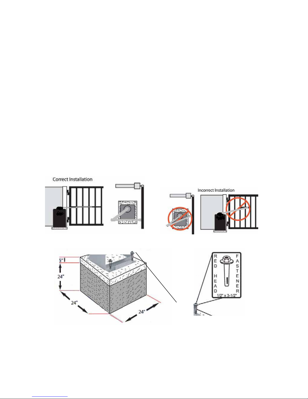
•The operator is appropriate for the construction of the gate (see the
ASTM F2200 standard) and the usage UL Class of the gate,
•It is recommended that all openings of a swing gate are guarded or
screened from the bottom of the gate to a minimum of 4 feet (1.22
m) above the ground to prevent a 2-1/4 inch (57.2 mm) diameter
sphere from passing through the openings anywhere in the gate,
and in that portion of the adjacent fence that the gate covers in the
open position,
•Guarding is supplied for exposed hinges
•The bottom of the gate has been constructed so that a “raking”
action has been eliminated
•All exposed pinch points are eliminated or guarded
2) The operator is intended for installation only on gates used for vehicles.
Pedestrians must be supplied with a separate access opening.
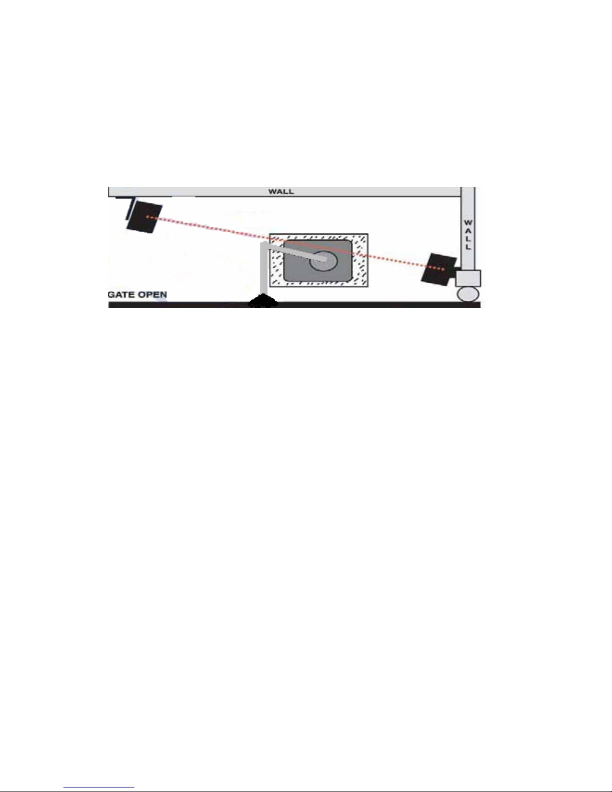
3) The gate must be installed in a location so that enough clearance is supplied
between the gate and adjacent structures when opening and closing to reduce
the risk of entrapment. Swinging gates shall not open “into” public access areas.
4

4) The gate must be properly installed and work freely in both directions prior to
the installation of the gate operator. Do not increase the operator amperage
levels beyond the required operable amounts to compensate for a damaged
gate.
5) For gate operators utilizing Type D protection:
•The gate operator controls must be placed so that the user has full
view of the gate area when the gate is moving,
•The placard be placed adjacent to the controls,
•An automatic closing device (such as a timer, loop sensor, or
similar device) shall not be employed
•No other activation device shall be connected.
6) Controls must be far enough from the gate so that the user is prevented from
coming in contact with the gate while operating the controls. Controls intended to
be used to reset an operator after 2 sequential activations of the entrapment
protection device or devices must be located in the line-of-sight of the gate.
Outdoor or easily accessible controls shall have a security feature to prevent
unauthorized use.
7) All warning signs and placards must be installed where visible in the area of
the gate. A minimum of two placards shall be installed. A placard is to be
installed in the area of each side of the gate and be visible to persons located on
the side of the gate on which the placard is installed.
8) For gate operators utilizing a non-contact sensor such as a photo beam:
•See instructions on the placement of non-contact sensors for each
type of application,
•Care shall be exercised to reduce the risk of nuisance tripping,
such as when a vehicle, trips the sensor while the gate is still
moving
•One or more non-contact sensors shall be located where the risk of
entrapment or obstruction exists, such as the perimeter reachable
by a moving gate or barrier.
9) For a gate operator utilizing a contact sensor such as an edge sensor:
•One or more contact sensors shall be located where the risk of
entrapment or obstruction exists, such as at the leading edge,
5

trailing edge, and post mounted both inside and outside of a
vehicular horizontal Swing gate.
•One or more contact sensors shall be located at the bottom edge of
a vehicular vertical lift gate.
•One or more contact sensors shall be located at the pinch point of a
vehicular vertical pivot gate.
•A hardwired contact sensor shall be located and its wiring arranged
so that the communication between the sensor and the gate
operator is not subjected to mechanical damage.
•A wireless contact sensor such as one that transmits radio
frequency (RF) signals to the gate operator for entrapment
protection functions shall be located where the transmission of the
signals are not obstructed or impeded by building structures,
natural landscaping or similar obstruction. A wireless contact
sensor shall function under the intended end-use conditions.
Before installation:
•Read and follow all instructions
•Verify that the IQ Gate Systems operator that is being installed is the
correct operator for the gate.
•Make sure that the gate has been properly installed and swings freely and
level throughout its travel. Repair or replace any damaged or unsafe
hardware. A gate that swings free of friction and binding will greatly
increase the life of the gate operator.
•Review the operation of the system and the customers needs to make the
installation as easy and efficient as possible.
•This gate operator is intended for vehicular gates only. A separate
entrance must be provided for pedestrian use.
•Please conform with the UL and ASTM standards on building safe and
approved gates
6

During installation:
•Install the gate operator on the secured side of the property and away
from public access.
•Be mindful of moving parts and pinch points. Avoid close proximities.
•Installation of contact and non-contact sensors such as edges and
photoelectric sensors is suggested to enhance the prevention of
entrapment.
•Determine the best level of open and close force for the installation. An
improper level will defeat the inherent current sensing purpose and make
the installation unsafe. By utilizing the “Motor Diagnostic” feature;
proper and accurate levels can be obtained when adjusting the open and
close force settings. Improper testing and setting of the force
adjustment can increase the risk of serious injury or death.
•Mount all access controls away from the gate a recommended minimum
distance of 10 feet. The gate must be in full view of controls but out of
reach.
After Installation:
•Review ALL safety instructions with the end user. Explain the basic
operation and features including safety precautions of the entire gate
operator system. Don’t forget to include how to disconnect power to the
operator and how to operate the gate manually.
•Attach all warning signs and placards as well as your own business
contact information to the gates. It is recommended that you take a picture
of the gates with the warning signs in place and record the date of the
photo. Keep for your records.
7

•SAVE ALL INSTRUCTIONS. Leave a copy of the manual and your
contact information with the end user.
Preparing to install the IQ-500
Consider the following when installing an IQ-500:
•Survey the desired location for the gate. Make sure that the opening is far
enough away from a main road or heavy traffic. Be sure to allow enough
distance away from the road so that a vehicle can approach the gate
without obstructing traffic. Twenty-five feet from the road should be
sufficient, but compliance with local codes should be observed.
•Keep power requirements in mind. The IQ-500 is capable of operating
with a supply of power from a solar panel that consists of at least 20 watts.
AC power is recommended to consist of 110 to 220 volts. AC power is the
preferred method of supply.
•Depending on soil conditions, set the concrete pad at least 2 feet in the
ground with an abundance of concrete. Check and conform to local codes.
•Install the gate with the incline of the road in mind. For proper operation,
the gate must swing back and forth at a level plane.
For Master / Slave Applications:
•The recommended installation of a master/slave or bi-parting swing gate is
to pull motor and limit switch wires across the road to the “master”
operator. This kind of setup allows for easy programming and servicing of
the gate operators. If it is desired to have a Motor Board in each operator,
the required number and gauge of wires will remain the same.
The following is the preferred master/slave wiring requirements:
8

•Be sure to provide a ¾” conduit between the two gates if they will be set
up as bi-parting. A minimum of at least 8 comm. wires and 2 power wires
are required for the IQ-500 to function with the greatest amount of
accuracy. A CAT5e and a 18-16 gauge 2 conductor cable will be
sufficient. The 16 gauge wires are to be provided for the motor power.
They will connect the RED and BLACK wires from the motor to the
MOTOR A and B terminals on the Motor Board.
•Utilize the Cat5e cable to terminate the open and close limit switches and
the Encoder wires from the slave connection terminal block. Connect
these wires in the Master operator on the M-2 motor board. The Encoder
and the limit switches all utilize a common ground.
•When programming the IQ Control Board for a Master / Slave application,
be sure to change the number of operators in the “Motor Drive Menu” to 2
operators. Also, make note of what operator is Motor 1 and what operator
is Motor 2 when selecting the on board slide switch on the motor board
labeled “M1 – M2”.
Installing the IQ-500
Be sure to follow these instructions:
•Bolt the IQ-500 onto a concrete pad
9

•Tighten all necessary bolts and prepare the gate and operator for motion
•Properly secure and attach the desired form of power in the control box
where power termination is labeled.
•Attach the battery wires to the batteries after the AC power has been
terminated and energized.
10

DO NOT REVERSE BATTERY POLARITY AT THE
BATTERY OR THE CIRCUIT BOARD. SEVERE
DAMAGE WILL OCCUR
The IQ-500 is a 24 volt DC gate operator. Utilizing (2) 12 vdc
batteries, the batteries must be connected in series, and then
the positive (+) power wire (RED) is to be connected to the
positive (+) battery terminal
•For Solar powered IQ-500 operators, the AC power supply
should be disconnected and removed. The Solar panel
should be wired into the power terminal block or solar
regulator (if provided).
•Take note of the software version on the LCD display upon power up.
11

Limit Settings
Setting the Gate Direction
•If the gate operator opens to the Right, the red motor wire will need to be
inserted into the Motor A terminal, with the Black motor wire being inserted
in the Motor B terminal. If the gate opens to the Left, the Red wire should
be inserted into the Motor B terminal, with the Black motor wire being
inserted into the Motor A terminal.
•The open and close limit switch wires will need to be switched accordingly.
Limit Switches
•IQ-500 Left Hand:
Bottom limit switch is the open limit
•IQ-500 Right Hand:
Top limit switch is the open limit
12

Wiring the IQ Control Board
The IQ Control board utilizes spring loaded terminal connections. To connect or
disconnect wires, push the white prong inwards towards the circuit board using a
3/16th inch blade screwdriver; insert or remove the desired wire, and release the
pressure on the terminal spade.
The IQ control board has numerous terminals to accommodate your entire
accessory wiring needs. The IQ control board uses pull down contacts so that
the ground or “GND” terminals should be used as the common contact to
complete the circuit for your normally open contacts. The IQ control board also
consists of 2 separate power output supplying areas. The Red terminals located
at the far most bottom right corner of the Terminal board are labeled {+ 12V}.
These 4 terminals can be used for your 12 vdc positive power output terminals
and are only designed for 12vdc accessory power. Maximum output is 125ma.
13

The 3 Red terminals that are located directly above these are labeled: {28/14
VDC}. These 3 terminals are whatever voltage that the operator is being
supplied with, rather it be 12 vdc or 24 vdc.
All of the GND terminals on the board may be used for the “ – “ power terminal
or for a common contact.
The 6 terminals at the top right corner of the terminal board are for the
termination of ground loops. These terminals correspond with the 3 available
plug-in loop detector slots. The loop detector slots are available for use as a
EXIT, SAFE and AUX configuration.
•The EXIT detector will provide an open contact to the controller and will
display “Exit Loop/Term”.
•The SAFE detector will provide a “safe” or close-reversing contact to the
controller and will display “Safe Loop/Term”.
The AUX detector will provide the output contacts from the detector to the
terminals on the board labeled “A – AUX – B”. When a AUX loop is utilized and
detecting, the output from the detector will be able to be utilized from the Aux A
and B terminals and from here you can jump to whatever contact you would like.
For example, if you should require a shadow loop, insert the shadow loop wires
into the AUX loop terminals at the top right corner of the board and then use a
jumper wire and insert it between the “Aux A” and “Shadow” terminals.
14

140ma +12vdc
Use 24 vdc
power
To 24 vdc power
15

The IQ Control Board is equipped with (2) 15 amp programmable relays. These
relays can be configured to perform a variety of functions. The output terminals
for these relays are directly below there corresponding relay.
The IQ Control Board is also supplied with a programmable input terminal. A
contact closure between the AUX IN terminal and the GND terminal will activate
the function that the input terminal has been programmed to do.
The output relay functions and input terminal options can be programmed in the
Auxiliary Settings Menu.
Receive / Transmit LED’s
Close limit terminal
Open Limit
Terminal
Common
Motor Wire Terminals
16

Be sure to disconnect and disable any magnetic or other gate locks before
learning an operator
Programming the IQ Control Board
The following is a list of programming and available features. Please be aware
that the IQ control board is one of the most advanced gate operator circuit
boards available and take care when programming and choosing desired
features. Refer to this manual if a feature that you desire is needed or if any
changes are necessary to be made in the menus.
The IQ control board is divided into 7 menus. Using the round
rotating programming knob on the display board, you can scroll through the
menus and select an option or enter a menu by depressing the programming
knob. When changes are being made in any menus the programming “ *“ will be
displayed at the top left of the screen. The 7 menus consist of the following:
Adjust the Clock
Adjust Time Settings
Auxiliary Settings
Maintenance Menu
Motor Drive Menu
IQ Gate Learning
Error and Fault Log
To enter any of the menus, rotate the programming knob one click to the right, or
clockwise. The first option that will appear is “Enter Password / None”. This is
indicating that the menu is not being password protected. If the password
feature was/is being utilized then the appropriate password would need to be
entered prior to advancing into the menus past this point. After 1 second, the
“Enter Password / None” display will expire and “Adjust the Clock” will be
displayed. At this point, you have entered the menu and may scroll clockwise or
counter-clockwise to make the adjustments that you desire. To enter a menu,
scroll until the one you desired is displayed and push the programming knob to
enter. To exit a sub-menu, scroll all the way clockwise until “exit the sub-menu”
is displayed and then push the programming knob in. To exit the main menus,
just scroll all the way counter-clockwise until the time and date is displayed.
17

Adjust the Clock:
Adjust Date / Time
•Year =
•Month =
•Date =
•Day =
•Hour =
•Minute =
Exit the sub-menu
Adjust Time Settings
•Maximum Run Timer = adjustable from 10 to 90 seconds, this timer
amount represents the maximum number of seconds that the gate
operator can run in one direction
•Close Delay Timer = adjustable from OFF to 4:15, this timer represents
the amount of time from OFF to seconds to minutes of how long the gate
waits to close from the open limit after all open and hold open inputs are
removed
•One day holiday = Next: (adjustable up to 7 days in advanced) This
option is to be used to define what day of the week an upcoming holiday is
(if it is desired that the gate not open with the 7-day open timer on that
holiday)
•7-day open timer = (Completely Off, Off to next {next on program}, On)
this is the option in which the 7-day open timer could be activated
•P-1 Open @ 08:00am / Su Mo Tu We Th Fr Sa
(These P-* options are the programmable 7 day auto open timers. You can
choose the time and days that the gates automatically open and then close.
There are 4 available auto open time slots. To program, adjust the desired time
and then display what days you would like the timer to function. If a day is
undesired, move the cursor under that day and press the programming knob to
erase that day from the program. Then scroll clockwise and set the days and
time for the auto close).
•7Day Security Timer = (Completely Off, Off to next {next on program}, On)
(The security timer has 2 available time slots that can be programmed for desired
days and times to allow or secure 4 inputs. The inputs that can be secured are:
Open, Radio, Exit and AUX. To program a secured input, simply program the
desired time and the days to secure that input, and also when to release. Then
allow the inputs by scrolling to “Secure Inputs, Allow” screen and move the
cursor under a desired input. To secure that input, press the programming knob.
The inputs that remain displayed will be allowed during the Secured Input timer.
•Secure Inputs, Allow = Open, Radio, Exit, Aux
Exit the sub-menu
18

Auxiliary Settings / Enter to View/Adjust
•Aux Input Terminal
(These are available programmable inputs that can be programmed to take
on the function that is selected when the AUX terminal is activated)
oOpen
oSafe
oShadow
oFire
oClose
oPhoto Eye Close (stops the gate from closing but doesn’t reverse
the gate)
oAux Out 1 (momentary activation of Aux 1 output relay)
oAux Out 2 (momentary activation of Aux 2 output relay)
oToggle Aux 1 (toggles Aux 1 output relay on/off)
oToggle Aux 2 (toggles Aux 2 output relay on/off)
o7-day Open Timer Off (turns off the 7-day open timer until the next
open schedule)
•Aux 1 Output Relay
•Aux 2 Output Relay
(These are available options for the Aux 1/2 output relays to perform if
selected)
oPulse on Open Limit (a 2 second relay activation on the open limit)
oPulse on Close Limit (a 2 second relay activation on the close limit)
oHold on Open Limit (latches the relay on the open limit)
oHold on Close Limit (latches the relay on the close limit)
oPulse on Motor Open (a 2 second relay activation when gate is
opening)
oPulse on Motor Close (a 2 second relay activation when gate is
closing)
oHold on Motor Open (latches the relay when gate is opening)
oHold on Motor Close (latches the relay when gate is closing)
oHold on UL-325 Alarm (latches the relay upon a UL-325 alarm)
oAux Input Received (activates the relay when the Aux input is in
use)
oAC Power Loss (activates the relay upon AC power loss detection
which is measured when the gate receives less then 23.5 VDC)
oLow DC Power (activate the relay upon low DC power detection, a
value of equal to or less then 75% of full power supplied)
oThermostat Engaged (activates the relay when the thermostat is
engaged)
oMaintenance Request (activates the relay upon a maintenance
request)
19

•Recycle Test Mode = OFF, ON (This is for testing purposes. If selected, it
will cause the gate to cycle open and close unless stopped with the radio
input or turned off in this menu)
Exit the sub-menu
Maintenance Menu
•Main Power/Battery = 24 VDC or 12 VDC (should be set at 24VDC for IQ
Gate operators
•Maintenance Request in = Cycles or Days
•Maintenance Request after = _ _ Cycles or _ _ Days
•Current _ _ _ _ _ _ Cycles/Days – Enter to reset (pressing the
programming knob to enter will erase and reset the current maintenance
count)
•Total Operator Cycle = M1 00,000,000 (this is displaying the total
accumulated cycles and is non-resetable)
•Low Power Function =
Hold Open – the gate will hold open until battery is above 75% full
Normal – the gate will continue to function regardless of low power
Fire – the gate will only open from a FIRE input
•Alarm Relay = Pulsed or Continuous output
•Motion Warning Type =
3 Sec Pre-Warn – Activates the alarm relay for 3 seconds before
motion
Motion Warning – Activates the alarm relay 3 seconds before
motion as well as during gate motion
Off – no audible notification of gate motion
•Reset Password = None or New (press enter to setup a new password)
•Limit Secure = Off or On (this is fail-secure option recommended for use in
the IQ-5000 only)
•Input Contacts = Momentary or Constant (affects the OPEN and CLOSE
inputs) should be set on Momentary
•Stop Input = Normally Open(default) or Normally Closed
•De-Icing Mode = On or Off (see below)
•Activate De-Icing at Temp: 37 F = (user selectable temperature) this
temperature setting is used to activate the De-Icing mode if activated. It
can also be used to energize the output relays if they have been selected
to activate on a temperature selection
•Abrupt Reverse = Off or On (this selects rather the gate ramps down or
instantly reverses upon a input when closing) Should be set to OFF
•Motor Diagnostics View for M1 = Off or On (turns off or on the M1
diagnostics) (see below)
•Motor Diagnostics View for M2 = Off or On
•Temperature Cal Display = (allows the thermostat to be calibrated
accurately)
Exit the sub-menu
20
Table of contents
Other IQ Gate Systems Gate Opener manuals