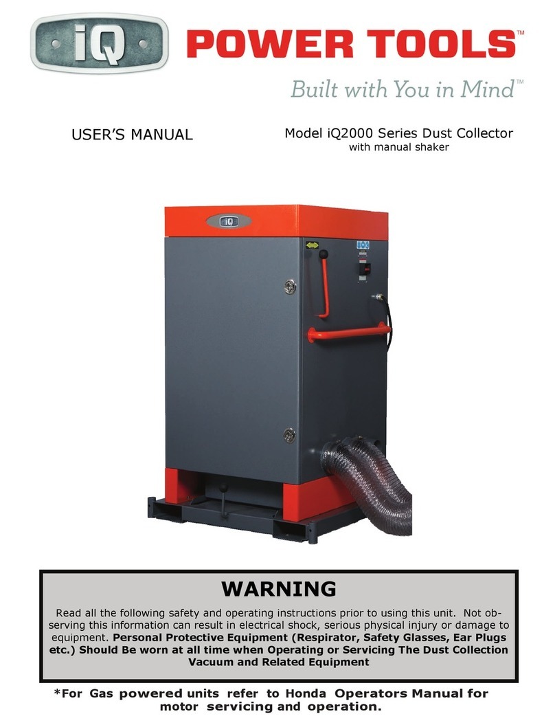
IQ 2003 S User manual

WARNING
Read all the following safety and operating instructions prior to using this unit. Not ob-
serving this information can result in electrical shock, serious physical injury or damage to
equipment. Personal Protective Equipment (Respirator, Safety Glasses, Ear Plugs
etc.) Should Be worn at all time when Operating or Servicing The Dust Collection
Vacuum and Related Equipment
Model iQ 2000 Series Dust Collector
with manual shaker
USER’S MANUAL
*For Gas
powered
units refer to Honda
Operators Manual
for
motor
servicing
and
operation.

Model # iQ-2003 S iQ-2007 T iQ-2013 G
Input Voltage
(VAC)
220 Single
Phase
480 Three
Phase
Gas Powered
Honda GXV160
Power Consumption
3 HP 7.5 HP 13 HP
Amperage (A) 15 7 N/A
Power Cable Length
10 Ft. 10 Ft. N/A
Fan Wheel
Diameter x Width
13½” x 2½” 13½” x 5” 13½” x 5”
Weight (LB) 400 430 400
Max Air Flow (CFM) 1700 4000 4000
Max Static Pressure
(INCH H²O)
88
8
Filter Area (SQ FT) 144, Polyester 144, Polyester 144, Polyester
Noise Level (dB A) 83 85 83
Hose Inlet Diameter
(INCH)
1(4”) 2(6”) 1(4”) 2(6”) 1(4”) 2(6”)
Size W x L x H 35” x 35” x 64” 35” x 35” x 64” 35” x 35” x 64”
Dust Capacity
(Cubic Ft.)
1.5 1.5 1.5
2
Specifications
*For Gas
powered
units refer to Honda
Operators Manual
for
motor
servicing
and
operation.

ITEM NO IQ-2000 PART # DESCRIPTION
1IQ2-P001 Enclosure Top
2IQ2-P002 Main Door
3IQ2-P003 Dust Tray
4IQ2-P004 Fork Tube Base
5IQ2-P005 Dust Tray Gasket
6IQ2-P006 Filter Element Assembly
7IQ2-P007 Manual Shaking Handle
8IQ2-P008 Main Door Gasket
9IQ2-P009 Door Knob
10 IQ2-P010 Grab Bar
13 IQ2-P013 Auxiliary Cap
1
2
3
4
5
6
7
8
9
10
12
PARTS LIST——Model iQ-2000
3

PARTS LIST—iQ MOTOR OPTIONS
IQ—2003S PART # DESCRIPTIONS
IQ3S—P002 Fan 13 1/2 X 2 1/2 CW
IQ3S—P003 Fan Housing with Motor Plate
IQ3S—P004 Manual Motor Starter with Adjustable
Overload Relay
IQ3S—P005 3 Wire Power Supply
iQ 2003S
IQ—2013G PART # DESCRIPTIONS
IQ13G—P001 13 HP Gas Honda GXV390 Motor
IQ13G—P002 Throttle Control
IQ13G—P003 Off/On Switch
IQ13G—P004 Fuel Line
IQ13G—P007 12V Battery
IQ13G—P008 Throttle Mount Plate
IQ13G—P009 Fuel Tank
IQ13G—P010 Fan 13 1/2 X 5 CW
IQ13G—P011 Fan Housing with Motor Plate
IQ13G—P012 Motor Push Start Button
IQ13G—P013 Battery Cable
iQ 2013G*
IQ—2007T PART # DESCRIPTIONS
IQ7T—P001 7.5 HP 460V/Three Phase Motor
IQ7T—P002 Fan 13 1/2 X 5” CW
IQ7T—P003 Fan Housing with Motor Plate
IQ7T—P004 Manual Motor Starter with Adjustable
Overload Relay
IQ7T—P005 4 Wire Power Supply
iQ 2007T
*For Gas powered units refer to Honda Operators Manual for
parts informaon, motor servicing and operaon.

IMPORTANT PRECAUTIONS
It is the owner’s responsibility, to inform all users regarding the operating and
safety precautions of this unit.
1. Be sure that the unit is disconnected from the power source prior to any service,
cleaning or maintenance.
2. Grounding–Unit must be grounded. Verify that the green wire in the power cable
is properly connected to a secure earth ground.
3. Power Hook-up–The unit is designed to be operated from either a single phase or
three phase power source, depending on the model. When an extension cord is
needed, the extension cord must be of the same or larger gauge to prevent loss of
power or overheating of the cable.
4. Overload Circuit Breaker–Make sure that the overload circuit breaker is set to
proper amperage, which maybe 15A or 7A, depending on the model.
5. Static Shock–Static shock is common in areas with relatively low humidity and is
not an indicator that the unit is performing improperly.
6. Dry Pick-up–Do not vacuum toxic, combustible, or other hazardous materials such
as: asbestos, arsenic, barium, beryllium, lead, or pesticides. Do not vacuum weld-
ing fumes, burning cigarettes, ashes, matches or other similar materials.
7. Never operate the unit in the presence of flammable vapors, aerosol products or
near the spraying of flammable liquids, i.e. paints and oils.
8. Do not operate the unit without the filter tubes in place.
9. Lock option casters in place when unit is in operation or storage.
10. Dust bucket release handle must be in upright position prior to operation of the
unit.
11. Never leave the unit unattended while it is powered on.
12. Do not put hair, clothing or body parts in front of the unit’s hoses or suction inlets
while the unit is powered “on”.
13. Transport, operate and store the unit on level surfaces to ensure the unit will re-
main stationary.
OPERATING INSTRUCTIONS
1. Power Hook-up–Electrical power
hook-up must be performed by a li-
censed electrician in accordance with
the applicable electrical codes. Con-
firm that motor rotation is in the direc-
tion of the arrow inscribed on the unit.
2. Inlet Hose/Duct Installation–At-
tach the proper diameter hose to the
corresponding suction inlets using con-
ventional hose clamps. Auxiliary inlet
must be covered with cap when not in
use to ensure proper suction. Hoses
and clamps should be checked regular-
ly for adjustments and signs of wear.
5

3. Operating of Casters (Optional) –To lock casters–Pull caster hand lever in up-
right position, perform this function for each caster. This will ensure unit will remain
stationary while in use or being stored.
To unlock casters- push caster hand lever in downward position. Each caster must
be unlocked in order to relocate the unit.
Removing casters–First, lock all casters. Lift unit with forklift (please refer to
Item 4) to an adequate height. Provide support beneath the caster and remove re-
taining pin in from shaft. Slide each caster out of it’s shaft. Place each retaining pin
around the corresponding wheel stow and slide each caster into the wheel stow
housing.
Installing casters–Unit must be secured to a forklift (please refer to Item 4). Re-
move each caster and retaining pin from the wheel stow housing; slide each caster
into it’s shaft and secure with a retaining pin. Lock each caster prior to lowering unit
from forklift, to ensure that unit will remain stationary on surface.
4. Prepare for Transport–Moving and lifting unit by forklift- Verify that the unit is
not plugged into power source, main door and dust bucket must be secure and cast-
ers locked. Align forklift with fork tubes on the base of the unit, precede forward
until fork is securely inserted in tubes. Lift unit to an adequate height in order to
remove casters. Unit can now moved to the desired location. If unit is being trans-
ported, tie down unit securely to a fixed position.
5. Power On–The on/off switch is located on the side panel of the unit. If the unit
does not power on, or shuts down after prolonged use in high temperature environ-
ments, the thermal overload protection circuit
may have become activated. If so, please wait
10 minutes before powering on again.
6. Shaking Operation- This unit is equipped
with a shaking mechanism to clear the filter
element of dust for optimum suction. Before
and during use, (30-60 min. as needed) peri-
odically power off the unit, the manual shaking
handle should be moved vigorously up and
down ten times, power on unit.
OPERATING INSTRUCTIONS
6

1. Changing Filters–Filter tubes are designed to provide a long service life. Howev-
er, depending upon usage and the kind of materials vacuumed, filters may need re-
placement every one to three years. Replace filter tubes as follows:
a. Unplug unit from power source.
b. Vigorously move the manual shaking handle up and down ten times.
c. Open main door by turning the two door knobs counterclockwise.
d. Inside the main enclosure, locate and remove the hitch pin clip (the hitch pin clip
attaches the arm of the manual shaking handle to the filter hanger assembly).
e. Pull the manual shaking handle outward to release the filter hanger assembly.
f. Remove all filter tubes from the metal filter housing plate by firmly squeezing and
pulling in an upward motion the cuff ring (the cuff ring is located at the lower end of
each filter tube) of each filter tube. Use care during this operation in order to reduce
any airborne dust that may be released.
g. When all filter tubes have been released from the metal filter housing plate, pull the
entire filter hanger assembly forward.
h. Remove and set aside all hitch pin clips from the filter hanger assembly.
i. Slide all filters tubes off the filter hanger assembly and properly dispose of all used
filter tubes
j. Replace with new filter tubes.
k. Reassemble by reversing these steps.
2. Lubrication–No lubrication is necessary. However, certain parts of the vacuum as-
sembly are subject to wear and should be replaced as necessary, depending upon
operating conditions.
Caution: During reassembly verify that the cuff ring for each filter tube is snugly
positioned in the metal filter housing plate. Do not use the unit, if the cuff rings
are not snugly positioned in the metal filter housing plate.
7. Emptying the Dust Drawer–The dust drawer must be emptied of debris on a
regular basis. First, turn unit “off” and unplug from power source or lock out. Rotate
the dust drawer release lever clockwise one-quarter turn, lower and release. Gently
slide the drawer forward and remove the plastic liner (if applicable) and replace with
a new plastic liner. Reverse these steps for reinstallation. Verify that the drawer is
properly positioned on reinstallation and the gasket has formed an adequate seal.
Failure to do this may cause a vacuum leak and gasket damage.
OPERATING INSTRUCTIONS
MAINTENANCE
!
!
7

P.O. Box 7449
Moreno Valley, CA 92552
Tel: 888-274-7744
www.iqpowertools.com
8
LIMITED WARRANTY
IQ Power Tools warrants this equipment to the original owner against
defective materials or workmanship for a period of one year from the
date of purchase. IQ Power Tools’ responsibility under this warranty is
limited to the repair or replacement of defective parts and reserves the
right to determine whether the failure is due to defective material, work-
manship or other causes. Failures caused by alteration or misuse are
not covered by the warranty.
All warranty repairs must be done by IQ Power Tools or an authorized
service representative. Any repair to the equipment other than by these
authorized facilities voids this warranty. These rights under this warranty
are limited to the original owner and may not be transferred to subse-
quent owners.

Built with You in Mind
Heavy-duty dust collection system for
20" & 24” masonry saws.
&
i
Q
SmartTable®
Dry cut masonry products dust free.
™
Patented
i
Q
SmartTable™

i
Q2003 S SPECIFICATIONS
VOLTAGE 220
v
Single Phase
HOSE INLET
DIAMETER
1
qty @
4"
2
qty @
6"
AMPERAGE 15
Amps
MAX AIR FLOW 1700
CFM
MOTOR POWER 3
hp
MAX STATIC
PRESSURE 8" H20
POWER CABLE 10
ft
FILTER AREA 144
sq ft
FAN WHEEL 13.5"
dia
× 2.5"
w
FILTER TYPE Polyester
WEIGHT 400
lbs
DUST CAPACITY 1.5
cu ft
DIMENSIONS 35"
w
× 44"
l
×64"
h
NOISE LEVEL 83
d
b a
i
Q2007 T SPECIFICATIONS
VOLTAGE 480
v
Three Phase
HOSE INLET
DIAMETER
1
qty @
4"
2
qty @
6"
AMPERAGE 9.2
Amps
MAX AIR FLOW 4000
CFM
MOTOR POWER 7.5
hp
MAX STATIC
PRESSURE 8" H20
POWER CABLE 10
ft
FILTER AREA 144
sq ft
FAN WHEEL 15"
dia
× 5"
w
FILTER TYPE Polyester
WEIGHT 430
lbs
DUST CAPACITY 1.5
cu ft
DIMENSIONS 35"
w
× 44"
l
×64"
h
NOISE LEVEL 85
d
b a
i
Q2013 G SPECIFICATIONS
VOLTAGE Gas Honda
GXV390
HOSE INLET
DIAMETER
1
qty @
4"
2
qty @
6"
AMPERAGE N/A MAX AIR FLOW 4000
CFM
MOTOR POWER 13
hp
elec. start MAX STATIC
PRESSURE 8" H20
POWER CABLE N/A FILTER AREA 144
sq ft
FAN WHEEL 15"
dia
× 5"
w
FILTER TYPE Polyester
WEIGHT 430
lbs
DUST CAPACITY 1.5
cu ft
DIMENSIONS 35"
w
× 44"
l
×64"
h
NOISE LEVEL 85
d
b a
Patented
i
Q
SmartTable™
collects dust as you cut
Long-lasting polyester filters with
manual shaker handle
Fork tube base with available
casters for portability
Easy-to-use dust
collection drawer
Heavy-duty dust collection system for 20" & 24"
masonry saws. Dry cut masonry, concrete and
stone products with no dust and no wet cutting
problems.
24385 Nandina Ave. Suite B, Moreno Valley, CA 92552
888-274-7744
•
i
Q
PowerTools.com
™
No more wet cutting
Slurry, stained product and swpp’s: never
think about them again
Saves time and money
The time and money spent on dust or slurry
management and cleanup: it’s yours again
Gas or electric powered
Versatility on the job site: move the cutting
to the most ecient location, inside or out
This manual suits for next models
2
Table of contents
Other IQ Dust Collector manuals
Popular Dust Collector manuals by other brands

ISTblast
ISTblast DCM100 TO 330 instruction manual

FilterStream
FilterStream DustTamer Ultra D4500 instruction manual

Chiko
Chiko CBA-080AD instruction manual

Apex Digital
Apex Digital PWDC-5 Operation manual

Oneida Air Systems
Oneida Air Systems Dust Deputy AXD001004 owner's manual

Grizzly
Grizzly G0583 instruction manual