iqualitrol iVick-472H User manual

iVick‐472H/M
VickersHardnessTester
USAGEInstructionManual

www.iqualitrol.com, sales@iqualitrol.com 2
ServiceCall:+86‐13711988687
Contents
One Precautions────────────────────────────────── 2
Two BriefIntroduction────────────────────────────── 2
Three ExternalStructure────────────────────────────── 3
Four TechnicalSpecifications────────────────────────── 4
OpticalSystem──────────────────────────────── 4
TestForces────────────────────────────────── 4
Five InstallationoftheInstrument──────────────────────── 5
Six FunctionofEachKey──────────────────────────── 6
Seven HowtoCarryOuttheTest───────────────────────── 7
SelectionofTestForce─────────────────────────── 7
Zero‐settingofEyepiece────────────────────────── 7
MeasurementofDiagonal───────────────────────── 9
Eight RegulationoftheLightSource─────────────────────── 10
ChangeoftheLampBulbs───────────────────────── 10
Nine Cautions─────────────────────────────────── 11
Relationsamongtheminimumthicknessofthespecimen–thetest
force–thehardness─────────────────────────────
12
Ten AttachedTables─────────────────────────────── 13
Repetitionofthevalue‐indicationofVickershardnesstester─────── 13
Toleranceofthevalue‐indicationofVickershardnesstester─────── 13
Eleven Accessories(ThePackingList)─────────────────────── 14
OptionalAccessories──────────────────────────── 14

www.iqualitrol.com, sales@iqualitrol.com 3
ServiceCall:+86‐13711988687
One.Precautions
1. It is advisable to use the single‐phase 3‐pin plug for the electric connection on the present
instrument. The grounding end must be according to the stipulatedrequirementforearth
protecting.
2. Itisnecessarytoreadcarefullytheusageinstructionmanualbeforetheoperationofthepresent
instrument in order to know the operational procedures and the precautionssoastoavoidthe
damagestotheinstrumentandthepersonalsafetycausedbytheincorrectoperation.
3. Duringtheinstallmentandthe preoperational test,the stickingpaper thatprotectsthe indenter
againsttheshockduringthetransportationshouldbetakenoffcarefullybecausetheover‐strength
indoingitwouldaffectthepositionalprecisionoftheindenter.
4. Itisprohibitedtodismountandalternatewithoutpermissionalltheelectriccomponentpartsand
the switches as well as their fixed positions. Those who do such unwarranted actions will be
responsiblefortheirconsequences.
5. During the loading process, press the “START” key immediately in case of emergency, and the
instrumentwillstoploadingautomaticallyandreturntoinitialposition.
6. Duringtheloading,dwellingandunloadingprocess,presstheemergencystopbuttonimmediately
incaseofemergency,andtheinstrumentwillstoptestingautomaticallyandreturntoinitialpositio
n.
7. Our company tries to improve the quality of the hardness testers and renew their structure
continuously. In case the contents in the usage instruction manual are a bit different with the
actualstructureoftheinstrument,itishopedandapologizedforthefactthatthefurthernotice
willnotbegiven.
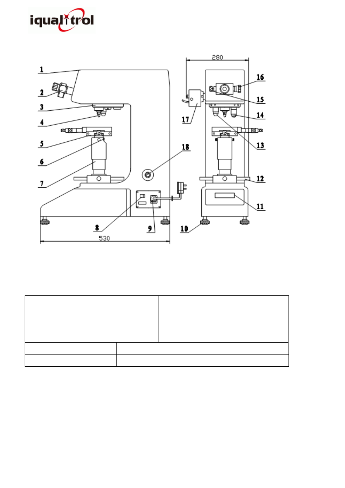
Two.BriefIntroduction
1. TheVickersHardnessTesterisanewandhigh‐techproductcombiningtheoptical,mechanicaland
electronic techniques, with a good aesthetic aspect, operational functions and reliability, and
henceitisanidealinstrumentforthetestingofVickershardness.
2. The instrument adopts closed‐loop loading control system, it makes the test accuracy improved
andtherepeatabilityandstabilityofthevaluebetter.
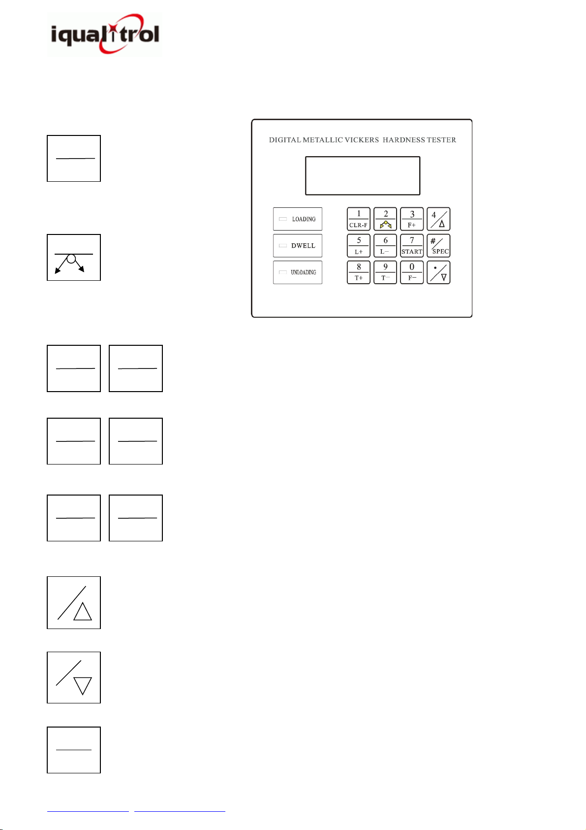
3. Withthesoftkeysonpanelboardforinputoperation,itcanpresetthetestingforcedwelltime,
adjustintensityoflightsourceandshowstheindentationlength,hardnessvalue,dwelltimeand
thetestnumber.Ithasthefunctionofautomaticshiftingbetweentheindenterandobjective.
4. Accordingtotheparticularrequirementsoftheclient,thetester can be equipped with CCD
indentation automatically measuring device. The instrument is suitable for the testing Vickers
hardness value of the micro and thin pieces, permeated and coated plane surface, the crisp
materialssuchastheagate,glassanditis,therefore,anidealhardnessmeasuringinstrumentfor
the scientific research institutes, the universities, the industrial production units and the
metrologicalinstitutes.

www.iqualitrol.com, sales@iqualitrol.com 4
ServiceCall:+86‐13711988687
Three.ExternalStructure
1.UpperCover 2.Eyepiece 3.AutomaticTurret 4.Indenter
5.CrossTestTable 6.Screw 7.LiftingScrew 8.PowerSwitch
9. Power Cord and
Fuse
10. Regulating
Screw 11.OperationPanel 12.HandWheel
13.10╳Objective 14.20╳Objective 15.PositionDrumWheel
16.MeasuringDrumWheel 17.LightSource 18.EmergencyStopButton
Four.TechnicalSpecifications
1TestForces:2.942(0.3kg)、4.903(0.5kg)、9.807(1kg)、19.61(2kg)、24.52(2.5kg)、
29.42(3kg)、49.03(5kg)、98.07(10kg)
Fig1

www.iqualitrol.com, sales@iqualitrol.com 5
ServiceCall:+86‐13711988687
2OpticalSystem:
3Carriageapplicationmethod:Automaticloading,dwellingandunloading
4Shiftingmethodofobjectivesandindenter:Automaticshifting
5Dwelltime:0~60s(5secondsasaunit)
6Power:(110~220)V,AC(60~50)Hz
7Specimen:
Max.height: 170mm
Max.depth: 130mm(Fromthecenter)
8Dimension(L×W×H):530×280×630mm
9Netweight:35kg
Eyepiece MeasuringObjective TotalAmplification Min.TestUnit
10×20
× 200×0.5μm
Notice:10×objectiveisusedforobserving,can’tbeusedformeasuring.
(BothobjectivescanbeusedtomeasurewiththeCCDdevice.)

www.iqualitrol.com, sales@iqualitrol.com 6
ServiceCall:+86‐13711988687
Five.InstallationoftheInstrument
1Operationalcondition:
1.1Roomtemperaturewithin(23±5)℃;
1.2Installedinahorizontalpositiononasolidbasement;
1.3Inanenvironmentwithoutanyshockorvibration;
1.4Inasurroundingwithoutanycorrodingagent;
1.5Relativeroomhumidityinferiorto65%.
2Unpackingandinstallation
2.1Cutthepacking belt,screwoffthescrewsfrombottomofpackingbox,andthentakeout the
instrumentandtheaccessorieskit;
2.2Placetheinstrumentonthepreparedsolidworkingtable;(fortheconstructionofthetable,see
Fig.2);
2.3Takeoutthe4horizontalregulatingscrewsoutoftheaccessorieskitandscrewthemintheholes
onthebasepaneloftheinstrument.Unpackthegauzebandwrappedontheliftingscrewand
thehandwheel;
2.4Tearlightlytheanti‐shockstickingpaperontheindenterwithboththehands.Cleantheindenter
lightlywiththelens‐cleaningpaperdippedwithsomeether(justmovethelens‐cleaningpaper
ontheindenterseveraltimesbyholdingthepaperonbothendswithhands);
2.5 Take off the dust‐protecting cover of the eyepiece tube andtaketheeyepieceoutofthe
accessories kit and then put it into the eyepiece tube. And then put the plug into the 5‐hole
socketontherightsideofthemainbody;
2.6Inserttheshaftintotheholeoftheliftingscrew;
2.7Takethelevel(thelevelinggauge)outoftheaccessorieskitandputitonthecrosstestingtable,
andregulatethe4horizontalscrewssoastomakethewaterbubblestayinthecenter.
250
90
(450)
Fig2

www.iqualitrol.com, sales@iqualitrol.com 7
ServiceCall:+86‐13711988687
Six.FunctionofEachKey
Upperkey:Digit.
Lower key: Zero setting
key,pressthiskeytoset
theresttestforcezero.
1
CLR‐F
0
F‐
3
F+
Upperkey:Digit.
Lowerkey:Testforceadding(reducing)key.Everypressingadds
(reduces)1step.
6
L‐
5
L+
Upperkey:Digit.
Lowerkey:Luminosityofthelightsourceadding(reducing)key.
0
T‐
3
T+
Upperkey:Digit.
Lower key: Time adding (reducing) key. Every pressing adds
(reduces)5seconds.
Upperkey:radixpoint.
Lower key: After press SPEC key, press this key to let the Lower keys
becomevalidandthecursorwilldisappear.
·
Upperkey:Digit.
Lowerkey:AfterpressSPECkey,pressthiskeytolettheUpperkeys(digit
keys)becomevalidandthecursorwillblink.
4
Upperkey:Digit.
Lower key: Start key, press this key to start the motor and apply test
force.
7
START
Fig.3
Upperkey:Digit.
Lower key: Switching key,
pressthiskeytoswitchthe
indenterandtheobjective.
2

www.iqualitrol.com, sales@iqualitrol.com 8
ServiceCall:+86‐13711988687
Seven.HowtoCarryOuttheTest
1.SelectionofTestForce
1.1Connectedthepowercord.Turnonthepowerswitch,andthelightingsourceandtheLCDscreen
are both light up at the same time. The indenter and the objective manually (iVick‐472H) or
automatically(iVick‐472M)shiftandthemeasuringobjectiveturntothefrontworkingposition.At
thispoint,thescreenshows(Fig.4):
D1/D2:Diagonallengthofindention;HV:Vickershardnessvalue;T:Dwelltime;
N:Numbersofmeasurements;F:Testforcevalue(N);
1.2Selectionoftestforce
Theupperandlowerkeyisvalidwhentheinstrumentturnson.
Press“F+”keyand“F‐”keytoselectthetestforce.
1.3Selectionoflightsource
Press“L+”keyand“L‐”keytoadjustthelightsource.
1.4Selectionofdwelltime
Press“T+”keyand“T‐”keytorevisethedwelltime.
2.Zero‐settingofEyepiece
2.1Rotatetheeyeguardtoenabletwograduatedlinesclearlyobservedintheeyepiece.
2.2Thezeropositionoftheeyepiecehasjustcalibratedbeforetheinstrumentisturnedoutthefactory.
Duringusage,itmaybecauseanerror,therefore,zeroposition setting should be carried out
periodically.Onceerrorappears,thezeropositionshallberegulated.Theregulationmethodisas:
Turnthedrumwheelstoenableinnersidesoftwograduatedlinescloselywithoutlimit,thelight
penetratespacebetweentheinnersidesofgraduatedlinesbecomesmallerandsmallertillreacha
criticalstatewithnolightslitbetweenthemtoallowlightpenetrate.The“0”positionsofrightdrum
wheelalsoshouldbealignedaswell.Ifthe“0”positionsarenotaligned,loosenthescrew,alignthe
#
SPEC
Doubleconfirmingkey:AfterkeyinD1,doublepressthiskeytoconfirm
D1. As the same, after key in D2, double press this key to confirm D2.
ThehardnessvalueonthescreenwillshowthehardnessvalueHV.
Special function key: Single press this key, then press key tolet
Upperkeysbecomevalid.Andasthesame,singlepressSPECkey,then
press keytoletLowerkeysbecomevalid.
D1:0.00HV:
D2:T:15N:
00
――――――――――――
Fig4

www.iqualitrol.com, sales@iqualitrol.com 9
ServiceCall:+86‐13711988687
zeropositions,andthenfastenthescrew(Fig.5).
3.StarttoTest
3.1Placethespecimenonthetestingtableandthenrotatethehandwheeltoraisethetabletofocus.
Putoneoftheeyesclosetotheeyepiecetoobserve,whenthespecimencomesintothedistance
of:
20╳objectiveabout4mm;10╳objectiveabout6mm(forobservation);
3.2Inthecenterofthevisionfieldoftheeyepieceappearsabrightspot,whichshowsitisverycloseto
thefocusingplane.Atthistimeraisethetestingtableupslowlyuntiltheblockorspecimensurface
formsaclearimageintheeyepiece,whichmeansthefocusissuccessful.
3.3Afteralltheparametersareset,atthistime,thedistancebetweenthetopoftheindenterandthe
specimenplaneis0.4mm.
3.5Pressthe“START”keyonthepanelboard,theinstrumentstartstotest.(Ifthereisresttestforcein
thelowerleftcornerofscreen,press“CLR‐F”tosetzero.)
Theinstrumentappliesthetestforceautomatically:the(LOADING)LEDglitters;
Aftertestforceapplyingiscompleted,the(DWELL)LEDlightsup,and atthis time, the Dwell
Timeindicatedonthescreenshowsback‐countofthetimeselected;
Afterdwelltimeoftestforceisup,the(UNLOADING)LEDglitters, and the instrument
automatically unloads the testing force. When it becomes dark, the test force completes
unloading.
3.6Themeasuringobjectiveautomaticallyshiftstothefrontposition.
Fig5
Loosenthescrewsand
align0”positionsagain
Caution: When you revolve the tower, avoid touching the
objective and the indenter, otherwise, it would make the
indentationslideandglide.Whenyouadjustthefocus,takecare
nottoletthespecimencollidetheindenterortheobjective.The
collisionwoulddamagethecomponents.

www.iqualitrol.com, sales@iqualitrol.com 1
ServiceCall:+86‐13711988687
4.MeasurementofDiagonal
4.1Observetheindentationintheeyepiece;rotatethehandwheeltofocusuntiltheimagequalityof
indentationbecomeclearly.
4.2Rotatetheleftdrumwheeltoenabletheinnersideofleftgraduatedlinetangenttothelefttipof
thediagonallineoftheindentation.Thisoperationmakesthetwograduatedlinesmovetogether
(Fig.6).
4.3Rotatetherightdrumwheeltoenabletheinnersideofrightgraduatedlinetangenttotherighttip
ofthediagonallineoftheindentation.
4.4 Right drum wheel turns each cycle for 50 grids. If it turns4cyclesandover2grids,thatmeans
50×4+2=202grids.
4.5Press“SPEC”keyand“ ”key,thecursorwillblinkandthedigitkeysarevalid.
4.6Keyindigit202,thendoublepress“SPEC”keytoconfirmD1value.ThecursorwillmovetoD2.
4.7 Turn the eyepiece by 90°. Measure the other diagonal lengthjustasthesameway.Keyindigit
203.5; double press “SPEC” key to confirm D2 value. The screen will show hardness value
automatically:“HV:451.3”.
During the turning operation the eyepiece should move along the inner side of the tube
without any space between them; otherwise it would affect the correctness of the
measurement.
4.8Iftheoperatorisnotsureofthecorrectnessofpresentmeasurement,pleasekeyinD1andD2
values(grids)again.
4.9Afterthismeasurementiscompleted,pressthe“SPEC”key;then press the“ ”key to let the
cursordisappear.Thentakethenexthardnesstest.
4.10Whentheindentationobservedintheeyepieceistoolargeortoosmalltomeasureprecisely,itis
necessarytore‐selectthetestingforceaccordingtothethicknessandsizeofthematerialtosuit
therequirementsofthemeasurement.
Fig6

www.iqualitrol.com, sales@iqualitrol.com 1
ServiceCall:+86‐13711988687
Eight.RegulationoftheLightSource
1.Turnonthepowerswitchofthehardnesstesterandobservethelightsourceoftheeyepiece.
2.Lightintensitycanbeadjustedby“L+”and“L‐”onthepaneltoenableviewingvisionsoft.
3.Ifthelightsourceisnotsatisfied,fastentheScrewTwoinclockwisedirectiontomakethelightbeam
inthe visionfield equality.(Youcanloosenthe ScrewThreeandthenfastenthe ScrewTwoifit is
necessary.)(Fig.7)
4.LoosentheScrewOneandmoveitupanddown.
5.ChangeoftheLampBulbs
5.1Followinggoodsisrequired:
Newlamp(ahalogenlamp,12V,15~20W)
Dryandsoftcloth
5.2UnscrewingtheScrewtwoinanti‐clockwisedirection,pushtheBackCoverinleftdirectionas
arrowheadmarkedandmovetheBackCoverdown.
5.3Takeoutthebadlampandreplaceonanewlampandcleanthelampsurfacewithasoftcloth.
5.4EquiptheBackCoverreturnedasabovementionedprocedure.
NOTE:
1.Thepowerswitchofthehardnesstestermustbeshutoffbefore
the lamp replacement, because there is dangerous voltage in the
insideofhardnesstester.
2.Thereplacementlampandoriginallampmustbethesamesize
and model. It will damage the circuit of hardness meter if the
improperlampisequipped.
21.ScrewOne 22.ScrewTwo 23.HalogenLamp 24.BackCover 25.ScrewThree
Fi
g
7

www.iqualitrol.com, sales@iqualitrol.com 1
ServiceCall:+86‐13711988687
Nine.Cautions
1Thediamondindenter
1.1 The diamond indenter and the indenter axis are the important parts of the instrument, and
henceitisnecessarytotakecarenottotouchtheindenterduringtheoperation.
1.2Inordertoassuretheprecisionofthemeasurement,itisimportanttokeeptheindenterclean.
Ifitiscoveredwithgreaseordust,itshouldbecleanedcarefullywithabsorbentcottondipped
withalcoholorindustrialether,especiallythetipoftheindenter.
1.3Theroundcolumnofthe indenterismarkedwitha reddot.Ifthe indenterisonceunloaded,
takecaretomakethereddotfacethefrontaldirectionwhenitisreloaded,andthefocusofthe
diagonallineoftheindentationshouldbealignedwiththereddot.Itispossibletomakethe
alignmentofthecross‐shapedinthemicroscopelinewiththediagonallineoftheindentation.
Iftheindentationobservedisnotalignedwiththecross‐shapedline,pleaseunscrewthescrew
ontheindenter,turntheindenterabitandfastenthescrew,and then make the alignment
againthroughtestsuntilthealignmentisallrighttoyoursatisfaction(Fig.8).
2Theeyepiece
2.1Owingtothedifferenceofthepersonalvisions,thegraduatedlinesobservedinthevisionfield
oftheobjectivemayseemvague.Andaccordingly,theobservershouldadjustthelensinfront
oftheobjectiveaccordingtohispersonalvisionallinesoastomakethegraduatedlineobserved
inthevisionfieldclear.
2.2Ifthetestforceischangedortheinstrumentisrestarted,thezeropositionoftheeyepiecewill
moveaswell.Soitisnecessarytoresetzerobeforethemeasurementofdiagonal.Refertothe
methodofzero‐settingabove.
2.3Astheeyepieceisputintheeyepiecetube,itisnecessarytoturntheeyepieceby90ºduringthe
measurement of the two diagonal lines of the indentation. During the turning operation the
eyepiece should move along the inner side of the tube without anyspacebetweenthem;
otherwiseitwouldaffectthecorrectnessofthemeasurement.
Reddot
Fig8

www.iqualitrol.com, sales@iqualitrol.com 1
ServiceCall:+86‐13711988687
3Thespecimen
3.1Thesurfaceofthespecimenmustbeclean,asthegreaseorthedirtonthesurfacewouldmake
theedgeoftheimageoftheindentationvague,thusaffectingtheprecisionofthemeasurement.
Thespecimencanbecleanedbyalcoholandether.
3.2Whenthinfilaments,thinpiecesandsmallbitsareusedasthespecimens,thefilamentfixture,
the platelet fixture and the plane holder fixture should be used to hold the specimens
respectivelyonthecrosstestingtableforthemeasurement.Ifthespecimenistoosmalltobe
heldbythefixture,thespecimenshouldbeinlayedandpolishedforthemeasurement.
3.3 The minimum thickness of the specimen should be more than10timesthedepthofthe
indentation(Fig.9).Therecan’tbevisualdeformationtraceson the back of specimen after
testing.
Relationsamongtheminimumthicknessofthespecimen–thetestforce–thehardness
Fig9
VickersHardness(HV)
MinimumThicknessofSpecimen(mm)

www.iqualitrol.com, sales@iqualitrol.com 1
ServiceCall:+86‐13711988687
Ten.AttachedTables
1.Repetitionofthevalue‐indicationofVickershardnesstester
Table1
Standard
HardnessRange
RepetitionofDisplayedHardnessValue(%)
HV5~HV100 HV0.2~<HV5 <HV0.2
≤225HV ≤3 ≤6 ≤9
>225HV ≤2 ≤4 ≤5
HV:Vickershardness
2.Toleranceofthevalue‐indicationofVickershardnesstester
Table2
Hardness
Symbol
ToleranceoftheValue‐indication±%
Hardness HV
50 100 150 200 250 300 350 400 450 500 600 700 800 900 1000 1500
HV0.2 4 6 8 9 10 11 11 12 12
HV0.3 4 5 6 7 8 9 10 10 11 11
HV0.5 3 5 5 6 6 7 7 8 8 9 11
HV1 3 4 4 4 5 5 5 6 6 6 8
HV2 3 3 3 4 4 4 4 4 5 5 6
HV3 3 3 3 3 3 4 4 4 4 4 5
HV5 3 3 3 3 3 3 3 3 3 4 4
HV10 3 3 3 3 3333 33 3
HV20 3 3 3 3 3333 33 3
HV30 3 3 2 2 2222 22 2
HV50 3 3 2 2 2222 22 2
HV1003 222222222
1Whentheindentationdiagonallengthislessthan0.020mm,thetabledoesnotdisplaythevalue.
Forintermediatevalues,themaximumallowableerrorcanbeobtainedbyinterpolation.
3AbouttheMicroHardnessTestervalueinthetableis0.001mmorindentationdiagonallengthof
theaverageof2%ofthemaximumpermissibleerrorgiven,pleaseselectthebigger.

www.iqualitrol.com, sales@iqualitrol.com 1
ServiceCall:+86‐13711988687
Eleven.Accessories(ThePackingList)
Item
Description
Specification Quantit
y
No
. Name
Main
Instrument
1 HardnessTester 1set
2 VickersIndenter 1piece
3 Objective 10×,20×2pieces
Accessories
4 AccessoriesBox 1piece
5 Eyepiece 10×1piece
6 CrossTestTable 1piece
7 LevelRegulationScrew 4pieces
8 Level 1piece
9 Screwdriver 1piece
10 InternalHexangularSpanner 2.5mm 1piece
11 Dust‐PreventingCover 1piece
12 PowerSourceCable 1piece
13 Fuses 1A/250V,5×20mm 2pieces
14 HalogenLamp 12V,15~20W 1piece
15 VickersHardnessBlock 2pieces
Documents 16 UsageInstructionManual1copy
OptionalAccessories
PlateletFixturePlane‐holdingFixture
FilamentFixture KnoopIndenter
HardnessTestBlocks
MetallurgicalSpecimenCutterMetallurgicalSpecimenMountingPress
MetallurgicalSpecimenPolisherCCDImageMeasuringSystem
This manual suits for next models
1
Table of contents
Other iqualitrol Test Equipment manuals